 Small batches, high standards. Our rapid prototyping service makes validation faster and easier —

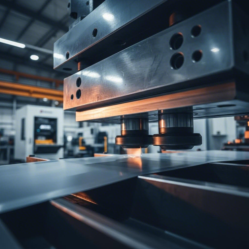
Preventing Galling In Stamping Dies: From Root Cause To Retrofit Fix precision stamping die forming metal with optimized surfaces designed to prevent galling damage
Understanding Galling and Its Impact on Stamping Operations
When metal surfaces slide against each other under intense pressure, something unexpected can happen. Instead of simply wearing down gradually, the surfaces can actually weld together—even at room temperature. This phenomenon, known as galling, represents one of the most destructive and frustrating challenges in stamping die operations. Understanding what is galling in metal is essential for anyone working to extend die life and maintain part quality.
Galling is a form of severe adhesive wear where contacting metal surfaces cold-weld together under friction and pressure, causing material transfer and surface damage without the application of external heat.
Unlike typical wear patterns that develop slowly over thousands of cycles, galling metal damage can occur suddenly and escalate rapidly. You might run a die successfully for weeks, only to find severe surface damage appearing within a single production shift. This unpredictability makes preventing galling in stamping dies a critical priority for manufacturing engineers.
The Microscopic Mechanics Behind Metal Adhesion
Imagine zooming in on any metal surface with an extremely powerful microscope. What appears smooth to the naked eye is actually covered with tiny peaks and valleys called asperities. During stamping operations, these microscopic high points on the die and workpiece surfaces come into direct contact under tremendous pressure.
Here's where galling begins. When two asperities press together with sufficient force, the protective oxide layers that normally cover metal surfaces break down. The exposed base metals come into intimate atomic contact, and atomic bonds form between them—essentially creating a micro-weld. As the stamping motion continues, these bonded areas don't simply slide apart. Instead, they tear.
This tearing action rips material from one surface and deposits it onto the other. The transferred material creates new, rougher asperities that increase friction and promote additional adhesion. This self-reinforcing cycle explains why galling often accelerates rapidly once it starts. Work hardening compounds the problem, as the transferred material becomes harder through strain hardening, making it even more abrasive against the die surface.
The strain hardening effect is particularly significant. Each deformation cycle increases the hardness of the adhered material, transforming what started as relatively soft transferred metal into hardened deposits that actively damage both the die and subsequent workpieces.
Why Galling Differs From Standard Die Wear
Many manufacturing professionals initially mistake galling for other wear mechanisms, leading to ineffective countermeasures. Understanding the distinctions helps you identify and address galling correctly:
- Abrasive wear occurs when hard particles or surface features plow through softer material, creating scratches and grooves. It develops gradually and predictably based on material hardness differences.
- Erosive wear results from repeated impact of particles or material flow against surfaces, typically appearing as smooth, worn areas with gradual material loss.
- Galling produces rough, torn surfaces with visible material buildup and transfer. It can appear suddenly and escalates quickly rather than progressing linearly.
The consequences of galling in stamping operations extend far beyond cosmetic surface issues. Parts produced from galled dies exhibit surface defects ranging from scoring marks to severe material pickup. Dimensional accuracy suffers as material transfer changes critical die geometry. In severe cases, gaulling can cause complete die seizure, halting production and potentially damaging expensive tooling beyond repair.
Perhaps most concerning is galling's potential to cause catastrophic failure. When material buildup reaches critical levels, the increased friction and mechanical interference can crack die components or cause sudden breakage during high-speed operation. This creates not only significant replacement costs but also safety hazards for operators.
Recognizing gaulling early and understanding its mechanisms forms the foundation for effective prevention strategies—which we'll explore throughout the remaining sections of this guide.
Material-Specific Galling Susceptibility and Risk Factors
Now that you understand how galling develops at the microscopic level, a critical question emerges: why do some materials cause far more galling problems than others? The answer lies in how different metals respond to the extreme pressures and friction inherent in stamping operations. Not all materials behave the same way under stress, and recognizing these differences is essential for preventing galling in stamping dies effectively.
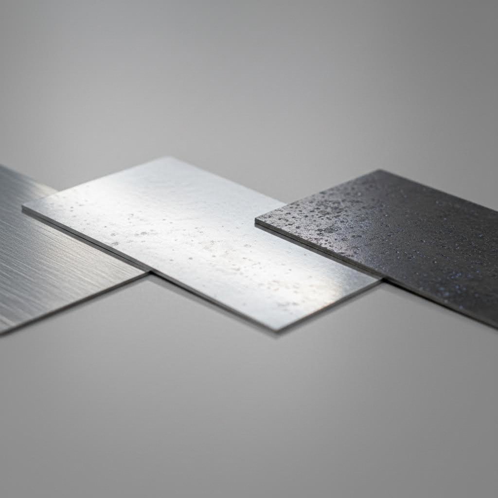
Three material categories dominate modern stamping applications—and each presents unique galling challenges. Understanding the specific vulnerabilities of stainless steel, aluminum alloys, and advanced high-strength steels (AHSS) allows you to tailor your prevention strategies accordingly. Let's examine what makes each material particularly prone to adhesive wear.
Stainless Steel Galling Characteristics
Ask any experienced die maker about their most challenging galling problems, and stainless stamping will likely top the list. Stainless steel has earned a well-deserved reputation as one of the most galling-prone materials in the stamping industry. But why does this otherwise excellent material cause such persistent problems?
The answer begins with stainless steel's protective chromium oxide layer. While this thin oxide film provides the corrosion resistance that makes stainless steel so valuable, it creates a paradox during stamping. The oxide layer is relatively thin and brittle compared to the oxides on carbon steel. Under the high contact pressures of stamping, this protective layer breaks down quickly, exposing the reactive base metal beneath.
Once exposed, austenitic stainless steels like 304 and 316 exhibit extremely high adhesion tendencies. The face-centered cubic crystal structure of these alloys promotes strong atomic bonding when clean metal surfaces contact each other. This makes metal-to-metal adhesion far more likely compared to ferritic or martensitic grades.
Compounding this problem is stainless steel's pronounced strain hardening and work hardening behavior. When stainless steel deforms during stamping, it work hardens rapidly—often doubling its initial yield strength through plastic deformation. This increased hardness makes any transferred material particularly abrasive. The yield stress of steel increases dramatically with each forming operation, creating harder and more damaging deposits on die surfaces.
Understanding the relationship between yield stress and yield strength helps explain this behavior. As stainless steel work hardens, both its yield strength and flow stress increase, requiring greater forming forces that generate more friction and heat—further accelerating galling.
Aluminum and AHSS Vulnerability Factors
While stainless steel may be the most notorious galling offender, aluminum alloys and advanced high-strength steels present their own distinct challenges that require different prevention approaches.
Aluminum's galling susceptibility stems from fundamentally different material properties. Aluminum alloys are relatively soft, with lower yield strength values compared to steel. This softness means aluminum deforms easily under die contact pressure, creating larger real contact areas between asperities. More contact area means more opportunity for adhesive bonding to occur.
Additionally, aluminum has a strong chemical affinity for tool steel. When the thin aluminum oxide layer breaks during forming, the exposed aluminum readily bonds to iron-based die materials. The transferred aluminum then oxidizes, creating hard aluminum oxide particles that act as abrasives—causing secondary wear damage beyond the initial galling.
Advanced high-strength steels present yet another set of challenges. AHSS materials, including dual-phase (DP), transformation-induced plasticity (TRIP), and martensitic grades, require significantly higher forming forces due to their elevated yield strength of steel values. These higher forces translate directly into increased friction and contact pressure between the die and workpiece.
AHSS also exhibits pronounced spring-back after forming. As the material attempts to return toward its original shape, it drags across die surfaces with additional friction. This post-forming contact can initiate galling on die areas that wouldn't normally experience problematic wear with conventional steels.
The combination of high forming forces and spring-back effects means that die designs successful with mild steel often fail when applied to AHSS applications without modification.
| Material Category | Galling Susceptibility | Primary Causes | Key Prevention Priorities |
|---|---|---|---|
| Stainless Steel (Austenitic) | Very High | Thin oxide layer breakdown; high work hardening rate; strong atomic adhesion tendency | Advanced coatings; specialized lubricants; polished die surfaces |
| Aluminum Alloys | High | Low hardness; large contact areas; chemical affinity to tool steel; oxide abrasiveness | DLC or chrome coatings; chlorinated lubricants; increased die clearances |
| Advanced High-Strength Steel (AHSS) | Moderate to High | High forming forces; spring-back friction; elevated contact pressures | Hardened die materials; optimized radii; high-performance coatings |
As you can see, each material category demands a tailored approach to galling prevention. The strain hardening and work hardening characteristics of your specific workpiece material directly influence which prevention strategies will prove most effective. In the following section, we'll explore how die design parameters can be optimized to address these material-specific vulnerabilities before problems ever develop.
Die Design Parameters That Prevent Galling
Here's a truth that every experienced tool and die maker understands: preventing galling in stamping dies is far easier—and far less expensive—during the design phase than after problems emerge in production. Once galling starts damaging your tooling, you're already fighting an uphill battle. The smart approach? Build galling resistance directly into your die design from the start.
Think of die design as your first line of defense. The parameters you specify on engineering drawings translate directly into how metal flows, how friction develops, and ultimately whether adhesive wear becomes a recurring nightmare or a non-issue. Let's examine the critical design variables that separate galling-prone dies from trouble-free tooling.
Optimizing Die Clearance for Different Materials
Die clearance—the gap between the punch and die—might seem like a simple dimension, but it profoundly affects galling behavior. Insufficient clearance forces material through a tighter space, dramatically increasing friction and contact pressure between the workpiece and die surfaces. This elevated pressure creates exactly the conditions that promote adhesive wear.
So what clearances should you specify? The answer depends heavily on your workpiece material and thickness. Here's where many tool and die operations go wrong: they apply universal clearance rules without accounting for material-specific behavior.
For mild steel, clearances typically range from 5% to 10% of material thickness per side. Stainless steel, with its higher work hardening rate and galling susceptibility, often requires clearances at the higher end of this range—sometimes 8% to 12%—to reduce the friction that triggers adhesion. Aluminum alloys benefit from even more generous clearances, often 10% to 15%, because their softness makes them particularly sensitive to tight-clearance friction.
The elastic modulus of your workpiece material also influences optimal clearance selection. Materials with higher Young's modulus of steel values spring back more forcefully after forming, potentially creating additional friction against die walls. AHSS materials, with their high strength and spring-back tendencies, often require careful clearance optimization combined with other design modifications.
Consider thickness effects as well. Thinner materials generally need proportionally larger percentage clearances because the absolute clearance dimension becomes so small that even minor variations create significant friction increases. A die maker working with 0.5mm stainless steel might specify 12% clearance, while the same material at 2.0mm thickness might perform well at 8%.
Surface Finish Specifications That Reduce Adhesion
Surface finish might not seem as obvious as clearance, but it plays an equally critical role in galling prevention. The roughness of your die surfaces affects both friction levels and lubricant performance—two factors that directly influence adhesive wear.
Surface roughness is typically measured as Ra (arithmetic average roughness) in micrometers or microinches. But here's what many engineers miss: the optimal Ra value varies significantly depending on the die component's function.
For punch faces and die buttons that contact the workpiece directly, smoother finishes generally reduce galling risk. Ra values of 0.2 to 0.4 micrometers (8 to 16 microinches) minimize the asperity peaks that initiate metal-to-metal contact. However, going too smooth can actually backfire—mirror-polished surfaces may not retain lubricant effectively.
Draw surfaces and blank holders benefit from a slightly different approach. A controlled surface texture with Ra values around 0.4 to 0.8 micrometers creates microscopic valleys that trap and retain lubricant during the forming stroke. This lubricant reservoir effect maintains a protective film even under high pressure conditions. The texture direction matters too—surfaces finished with tapered cutting or grinding patterns oriented perpendicular to material flow tend to retain lubricant better than randomly oriented finishes.
Here's the key insight: surface finish optimization is about balancing friction reduction with lubricant retention. The ideal specification depends on your lubrication strategy, forming pressures, and workpiece material.
- Die clearance optimization: Specify material-appropriate clearances (5-10% for mild steel, 8-12% for stainless, 10-15% for aluminum) to reduce contact pressure and friction that trigger galling.
- Surface finish specifications: Target Ra values of 0.2-0.4 μm for punch faces and 0.4-0.8 μm for draw surfaces to balance friction reduction with lubricant retention.
- Punch and die radii: Generous radii (minimum 4-6 times material thickness) reduce localized stress concentrations and prevent the severe metal flow that promotes adhesion.
- Draw bead design: Properly sized and positioned draw beads control material flow, reducing the sliding friction that initiates galling on blank holder surfaces.
- Entry angles: Gradual entry angles (typically 3-8 degrees) allow smoother material transition, minimizing abrupt contact pressure spikes.
- Material flow analysis: Map material movement during forming to identify high-friction zones requiring additional design attention or localized surface treatments.
Punch and die radii deserve special attention in galling prevention. Sharp radii create stress concentrations that force material to flow under extreme localized pressure—exactly the conditions where adhesive wear initiates. As a general guideline, radii should be at least 4 to 6 times the material thickness, with even larger values beneficial for galling-prone materials like stainless steel.
Draw bead design influences how material flows into the die cavity. Well-designed draw beads control material movement and reduce the uncontrolled sliding friction that often triggers galling on blank holder surfaces. The bead height, radius, and positioning all affect friction levels and should be optimized through simulation or prototype testing before final tool construction.
Entry angles represent another often-overlooked parameter. When material enters a forming cavity at an abrupt angle, contact pressure spikes dramatically at the entry point. Gradual entry angles—typically 3 to 8 degrees depending on the application—allow smoother material transition and distribute contact forces over a larger area.
Investing time and engineering resources in optimizing these design parameters pays dividends throughout the die's production life. The cost of CAE simulation and design iteration is typically a fraction of what you'd spend on retrofit solutions, coating repairs, or premature die replacement. With your die geometry optimized for galling resistance, you've established a solid foundation—but design alone isn't always sufficient for the most demanding applications. Modern coating technologies offer an additional layer of protection that can dramatically extend die life, which we'll explore next.
Advanced Coating Technologies for Galling Resistance
Even with perfectly optimized die geometry, some stamping applications push materials to their limits. When you're forming galling-prone stainless steel or running high-volume production with demanding cycle times, design optimization alone may not provide sufficient protection. This is where advanced coating technologies become game-changers—creating a physical and chemical barrier between your die surfaces and the workpiece.
Think of coatings as armor for your tooling. The right coating dramatically reduces the friction coefficient, prevents direct metal-to-metal contact, and can extend die life by factors of 10 or more in challenging applications. But here's the catch: not all coatings perform equally across different materials and operating conditions. Selecting the wrong coating can waste your investment or even accelerate die damage.
Let's examine the four major coating technologies used in preventing galling in stamping dies, and more importantly, how to match each technology to your specific application requirements.
Comparing DLC, PVD, CVD, and TD Coating Performance
Modern coating technologies fall into four primary categories, each with distinct deposition methods, performance characteristics, and ideal applications. Understanding these differences is essential for making informed coating decisions.
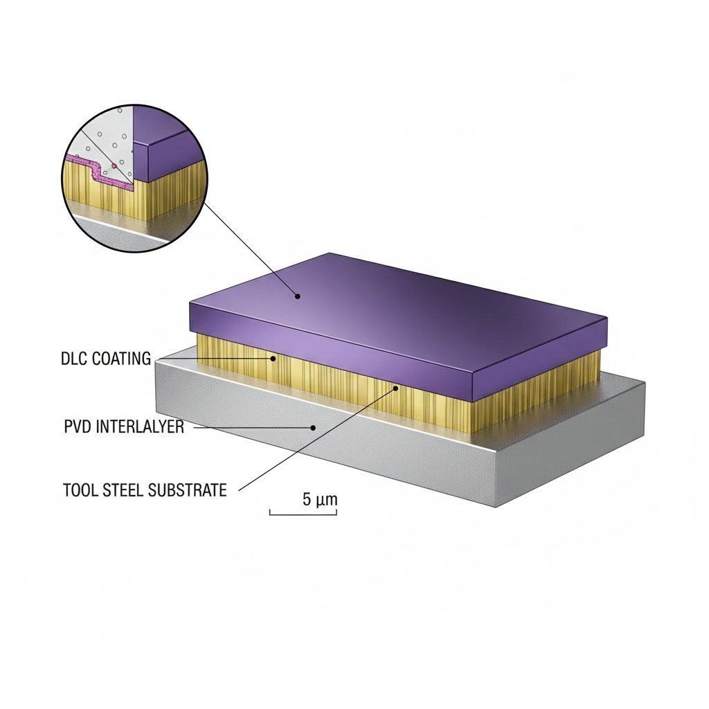
Diamond-Like Carbon (DLC) coatings have revolutionized galling prevention for aluminum and stainless stamping applications. DLC creates an extremely hard, low-friction carbon-based layer with friction coefficients as low as 0.05 to 0.15—dramatically lower than uncoated tool steel. The coating's amorphous carbon structure provides exceptional resistance to adhesive wear because aluminum and stainless steel simply don't bond well to carbon-based surfaces.
DLC coatings are typically applied through plasma-enhanced CVD or PVD processes at relatively low temperatures (150-300°C), which minimizes distortion of precision die components. Coating thickness typically ranges from 1 to 5 micrometers. However, DLC has limitations—it softens above approximately 300°C, making it unsuitable for high-temperature forming operations.
Physical Vapor Deposition (PVD) encompasses a family of coating processes including titanium nitride (TiN), titanium aluminum nitride (TiAlN), and chromium nitride (CrN). These coatings are deposited by vaporizing solid coating materials in a vacuum chamber and allowing them to condense on the die surface. PVD coatings offer excellent hardness (typically 2000-3500 HV) and good adhesion to properly prepared substrates.
The steel modulus of elasticity of your die material affects how PVD coatings perform under load. Because PVD coatings are relatively thin (1-5 micrometers), they rely on substrate support. If the underlying tool steel deforms excessively under contact pressure, the harder coating can crack. This is why substrate hardness and the elastic modulus of steel become critical considerations when specifying PVD treatments.
Chemical Vapor Deposition (CVD) produces coatings through chemical reactions of gaseous precursors at elevated temperatures (800-1050°C). CVD titanium carbide (TiC) and titanium carbonitride (TiCN) coatings are thicker than PVD alternatives—typically 5 to 15 micrometers—and offer exceptional hardness and wear resistance.
The high processing temperatures of CVD require careful consideration. Dies must typically be re-hardened and tempered after CVD coating, adding process steps and cost. However, for high-volume production where maximum die life is critical, CVD coatings often deliver the best long-term value despite higher initial investment.
Thermal Diffusion (TD) treatments, sometimes called Toyota Diffusion or vanadium carbide treatments, create extremely hard carbide layers by diffusing vanadium or other carbide-forming elements into the die surface at temperatures around 900-1050°C. Unlike deposited coatings that sit on top of the substrate, TD creates a metallurgical bond with the base material.
TD coatings achieve hardness levels of 3200-3800 HV—harder than most PVD or CVD options. The diffusion bond eliminates concerns about coating delamination that can affect deposited coatings. TD treatments are particularly effective for dies stamping AHSS and other high-strength materials where extreme contact pressures would damage thinner coatings.
Matching Coating Technology to Your Application
Selecting the right coating requires balancing multiple factors: your workpiece material, forming temperatures, production volumes, and budget constraints. Here's how to approach the decision systematically.
For aluminum stamping applications, DLC coatings typically offer the best performance. Aluminum's chemical affinity for iron-based materials makes it prone to adhesion, but DLC's carbon-based surface chemistry virtually eliminates this bonding tendency. The low friction coefficient also reduces forming forces, extending both die and press life.
Stainless steel stamping benefits from multiple coating options depending on the specific alloy and forming severity. DLC works well for lighter forming operations, while PVD TiAlN or CrN coatings provide better performance for deep drawing applications where contact pressures are higher. For the most demanding stainless applications, TD treatments offer the ultimate wear resistance.
AHSS forming typically demands the hardest coating options—CVD or TD treatments—to withstand the elevated forming forces these materials require. The investment in these premium coatings is often justified by dramatically extended die life in high-volume production.
Substrate preparation is critical for all coating types. Dies must be properly hardened, precisely ground, and thoroughly cleaned before coating. Any surface defects or contamination will be magnified after coating, potentially causing premature failure. Many coating service providers, including specialized heat treatment companies, offer complete preparation and coating packages to ensure optimal results.
| Coating Type | Friction Coefficient | Operating Temp Range | Coating Hardness (HV) | Best Material Applications | Relative Cost |
|---|---|---|---|---|---|
| DLC (Diamond-Like Carbon) | 0.05 - 0.15 | Up to 300°C | 2000 - 4000 | Aluminum, stainless steel, light forming | Medium-High |
| PVD (TiN, TiAlN, CrN) | 0.20 - 0.40 | Up to 800°C | 2000 - 3500 | General stamping, stainless steel, mild steel | Medium |
| CVD (TiC, TiCN) | 0.15 - 0.30 | Up to 500°C | 3000 - 4000 | High-volume production, AHSS, severe forming | High |
| TD (Vanadium Carbide) | 0.20 - 0.35 | Up to 600°C | 3200 - 3800 | AHSS, heavy stamping, extreme wear conditions | High |
Coating thickness considerations vary by technology. Thinner coatings (1-3 micrometers) maintain tighter dimensional tolerances but offer less wear reserve. Thicker coatings provide longer service life but may require adjustments to die clearances. For precision stamping applications, discuss dimensional impacts with your coating provider before processing.
Expected service life depends heavily on application severity, but properly matched coatings typically extend die life by 3 to 15 times compared to uncoated tooling. Some operations report coating investments paying for themselves within the first production run through reduced downtime and maintenance costs.
While coatings provide excellent protection against adhesive wear, they work best as part of a comprehensive prevention strategy. Even the most advanced coating cannot compensate for poor lubrication practices—which we'll address in the next section.
Lubrication Strategies and Application Methods
You've optimized your die design and selected an advanced coating—but without proper lubrication, you're still leaving your tooling vulnerable to galling damage. Think of lubrication as the daily protection your dies need, while coatings provide the underlying armor. Even the best DLC or TD coating will fail prematurely if lubricant selection and application aren't optimized for your specific operation.
Here's what makes lubrication both critical and challenging: the lubricant must create a protective barrier under extreme pressure, maintain that barrier throughout the forming stroke, and then often disappear before downstream processes like welding or painting. Getting this balance right requires understanding both lubricant chemistry and application methods.
Lubricant Types and Their Galling Prevention Mechanisms
Not all stamping lubricants work the same way. Different formulations protect against galling through distinct mechanisms, and matching the lubricant type to your application is essential for effective prevention.
Boundary lubricants form thin molecular films that adhere to metal surfaces and prevent direct contact between the die and workpiece. These lubricants work by creating a sacrificial layer—the lubricant molecules shear apart rather than allowing the metals to bond. Fatty acids, esters, and chlorinated compounds fall into this category. Boundary lubricants excel in moderate-pressure applications where a thin protective film is sufficient.
Extreme pressure (EP) additives take protection further by chemically reacting with metal surfaces under high temperature and pressure conditions. Common EP additives include sulfur, phosphorus, and chlorine compounds that form protective metal sulfides, phosphides, or chlorides at the contact interface. These reaction films are particularly effective for preventing galling during severe forming operations where boundary lubricants alone would fail.
Dry film lubricants offer an alternative approach that eliminates the mess and cleanup associated with liquid lubricants. These products—typically containing molybdenum disulfide, graphite, or PTFE—are applied as thin coatings that remain on the workpiece through forming. Dry films work well for applications where lubricant residue would interfere with subsequent processes or where environmental concerns limit liquid lubricant use.
- Straight oils: Best for heavy-duty stamping and deep drawing; excellent boundary lubrication; requires thorough cleaning before welding or painting operations.
- Water-soluble fluids: Easier cleanup and cooling properties; suitable for moderate forming; compatible with some spot welder welding applications with proper surface preparation.
- Synthetic lubricants: Consistent performance across temperature ranges; often formulated for specific materials like stainless or aluminum; lower residue than petroleum-based products.
- Dry film lubricants: Ideal when lubricant residue is problematic; effective for aluminum forming; may require pre-application to blank stock.
- EP-enhanced formulations: Required for AHSS and severe forming; sulfur or chlorine-based additives provide chemical protection under extreme pressure.
Material compatibility matters significantly when selecting lubricants. Aluminum alloys, for instance, respond well to chlorinated boundary lubricants that prevent the aluminum-to-steel adhesion that triggers galling. Stainless steel often requires EP additives to handle its high work-hardening behavior and adhesion tendencies. AHSS materials demand robust EP formulations that can maintain protection under the elevated forming pressures these materials require.
Application Methods for Consistent Coverage
Even the best lubricant fails if it doesn't reach the contact surfaces consistently. Application method selection affects both galling prevention effectiveness and production efficiency.
Roller coating applies lubricant to flat sheet stock as it feeds into the press. Precision rollers deposit a controlled, uniform film thickness across the entire blank surface. This method excels in high-volume progressive die operations where consistent lubrication of every blank is essential. Roller systems can apply both liquid lubricants and dry film products, making them versatile for different application requirements.
Spray systems offer flexibility for complex die geometries where lubricant must reach specific areas. Programmable spray nozzles can target high-friction zones identified through experience or simulation. Spray application works well for transfer die operations and situations where different die areas require different lubricant quantities. However, overspray and mist control require attention to maintain a clean work environment.
Drip lubrication provides a simple, low-cost approach suitable for lower-volume production or prototype operations. Lubricant drips onto the strip or blank at controlled intervals. While less precise than roller or spray methods, drip systems require minimal investment and work adequately for many applications. The key is ensuring adequate coverage of critical contact areas.
Flood lubrication applies excess lubricant to guarantee complete coverage, with surplus collected and recirculated. This approach is common in spin forming and other operations where continuous lubricant presence is critical. Flood systems require robust filtration and maintenance to prevent contamination that could cause surface defects.
Post-stamping process compatibility deserves careful consideration during lubricant selection. If your stamped parts require gas tungsten arc welding or alu mig welding, lubricant residues can cause porosity, spatter, and weak welds. Parts destined for welding typically need lubricants that either burn off cleanly during welding or can be removed easily through cleaning processes.
When reviewing welding drawings, you'll often encounter specifications indicated by a weld symbol or fillet weld symbol that assume clean surfaces. Chlorinated lubricants, while excellent for galling prevention, can create toxic fumes during welding and may be prohibited for parts entering welding operations. Water-soluble lubricants or specialized low-residue formulations often provide the best balance between forming performance and weld compatibility.
Parts destined for painting or coating require similar attention. Lubricant residues can cause adhesion failures, fisheyes, or other coating defects. Many manufacturers specify lubricants based on downstream cleaning capabilities—if your cleaning process can reliably remove a particular lubricant, it becomes a viable option regardless of residue characteristics.
Lubricant maintenance and monitoring ensure consistent protection throughout production runs. Regular testing of lubricant concentration, contamination levels, and EP additive depletion helps identify problems before galling occurs. Many operations establish scheduled testing protocols and maintain control charts to track lubricant condition over time. When a groove weld specification or other critical feature depends on surface quality, maintaining lubricant performance becomes even more important.
Temperature affects lubricant performance significantly. High-speed stamping operations generate heat that can thin lubricants, reducing their protective film thickness. Conversely, cold startup conditions may increase lubricant viscosity beyond optimal levels. Understanding how your lubricant performs across your actual operating temperature range helps prevent unexpected galling problems.
With proper lubricant selection and application methods in place, you've addressed a critical layer of galling prevention. But what happens when problems still develop despite your best efforts? The next section provides a systematic approach to diagnosing galling root causes when issues arise.
Systematic Troubleshooting When Galling Occurs
Despite your best prevention efforts, galling can still appear unexpectedly during production. When it does, you need more than guesswork—you need a systematic diagnostic approach that pinpoints the root cause quickly and accurately. Misdiagnosing galling often leads to expensive fixes that don't address the actual problem, wasting both time and resources.
Think of galling diagnosis like detective work. The evidence is right there on your die surfaces and stamped parts—you just need to know how to read it. The patterns, locations, and characteristics of galling damage tell a story about what went wrong and, more importantly, what to fix.
Step-by-Step Galling Diagnosis Process
When galling appears, resist the urge to immediately change lubricants or order new coatings. Instead, follow a structured diagnostic sequence that systematically eliminates potential causes:
- Stop production and document the condition: Before cleaning or modifying anything, photograph the affected die areas and sample parts. Note the exact press stroke count, shift, and any recent changes to materials, lubricants, or process parameters. This baseline documentation proves invaluable for correlation analysis.
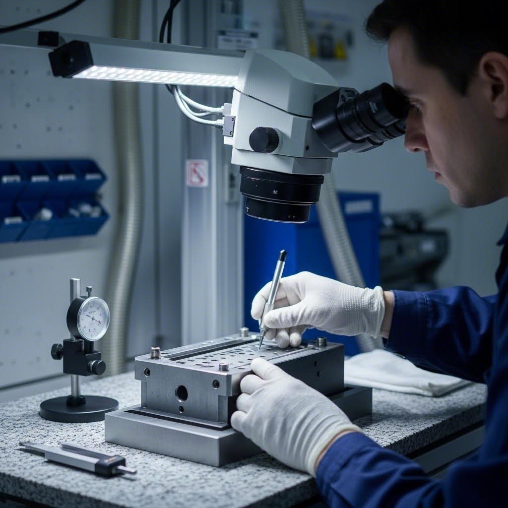
- Perform detailed visual inspection: Examine galling damage under magnification (10x-30x). Look for material buildup direction, surface tearing patterns, and the specific die components affected. Fresh galling appears as rough, torn surfaces with visible material transfer, while older damage shows burnished or smeared deposits.
- Map damage locations precisely: Create a sketch or overlay on die drawings showing exactly where galling occurs. Is it localized to specific radii, draw surfaces, or punch faces? Does it appear on entry zones, exit areas, or throughout the forming stroke? Location patterns provide critical diagnostic clues.
- Analyze the workpiece material: Verify that incoming material matches specifications. Check yield stress values, thickness measurements, and surface condition. Material variations—even within specification—can trigger galling in borderline applications. Understanding what yield strength your material actually exhibits versus nominal values helps identify material-related causes.
- Review lubricant condition and coverage: Inspect lubricant concentration, contamination levels, and application uniformity. Look for dry spots on blanks or signs of lubricant breakdown. The yield point at which lubricant films fail often correlates with increased forming pressure or elevated temperatures.
- Examine coating integrity: If dies are coated, look for signs of coating wear-through, delamination, or cracking. Coating failures often appear as localized areas where the substrate color shows through or where wear patterns differ from surrounding surfaces.
- Evaluate process parameters: Review press speed, tonnage, and timing. Check for changes in blank holder pressure or draw bead engagement. Even small parameter shifts can push a marginally stable process into galling territory.
Pattern Analysis for Root Cause Identification
The location and distribution of galling damage reveals its underlying cause. Learning to read these patterns transforms troubleshooting from trial-and-error into targeted problem-solving.
Localized galling at specific radii typically indicates design issues. When damage consistently appears at the same die radius or corner, the geometry may create excessive contact pressure or restrict material flow. This pattern suggests the need for radius modifications or localized surface treatment rather than wholesale lubrication changes. The deformation hardening occurring at these stress concentration points accelerates adhesive wear.
Galling along draw walls or vertical surfaces often points to clearance problems or coating breakdown. When material drags against die walls throughout the forming stroke, insufficient clearance forces metal-to-metal contact. Check for coating wear-through in these areas and verify clearance dimensions match specifications.
Random galling appearing across multiple locations suggests lubrication failure or material issues. If damage isn't concentrated in predictable areas, the protective system has broken down broadly. Investigate lubricant application coverage, concentration levels, or incoming material variations that might affect all contact surfaces equally.
Progressive galling that worsens from one area outward indicates a cascading failure. Initial damage—perhaps from a minor coating defect or lubrication gap—creates rougher surfaces that generate more friction, accelerating wear in adjacent areas. The yielding force required to form parts increases as damage spreads, often accompanied by rising press tonnage readings.
Understanding yield in engineering terms helps explain why galling propagates. Once material transfer occurs, the harder deposits increase local contact pressure, exceeding the yield point of the workpiece surface and promoting additional adhesion. This self-reinforcing mechanism explains why early detection is critical.
Documentation practices make the difference between recurring problems and permanent solutions. Maintain a galling incident log that records:
- Date, time, and production volume when galling was detected
- Specific die components and locations affected
- Material lot numbers and supplier information
- Lubricant batch and concentration readings
- Recent process changes or maintenance activities
- Corrective actions taken and their effectiveness
Over time, this documentation reveals correlations that single-incident analysis cannot. You might discover galling clusters around specific material lots, seasonal temperature changes, or maintenance intervals. These insights transform reactive troubleshooting into predictive prevention.
Once you've identified the root cause through systematic diagnosis, the next step is implementing effective solutions—whether that means immediate interventions for active problems or long-term retrofits to prevent recurrence.
Retrofit Solutions for Existing Dies
You've diagnosed the problem and identified the root cause—now what? When galling strikes dies already in production, you face a critical decision: fix what you have or start over with new tooling. The good news? Most galling problems can be resolved through retrofit solutions that cost a fraction of die replacement. The key is matching your intervention to the diagnosed cause and implementing fixes in the right sequence.
Think of retrofit solutions as a hierarchy. Some interventions deliver immediate relief with minimal investment, while others require more significant modifications but provide lasting protection. Understanding when to apply each approach—and when retrofit simply isn't viable—saves both money and production time.
Immediate Interventions for Active Galling Problems
When production is down and galling damage needs immediate attention, you need solutions that work fast. These first-response interventions can often get you running again within hours rather than days.
Surface reconditioning addresses galling damage that hasn't penetrated deeply into die surfaces. Careful stoning or polishing removes material buildup and restores surface geometry. The goal isn't achieving mirror finishes—it's removing the roughened, work-hardened deposits that perpetuate the galling cycle. For shallow damage, experienced tool & die technicians can recondition surfaces without affecting critical dimensions.
Lubricant upgrades provide immediate protection while you implement longer-term fixes. If diagnosis revealed lubrication failure, switching to a higher-performance formulation with enhanced EP additives can stabilize the process. Sometimes simply increasing lubricant concentration or improving application coverage resolves borderline galling situations. This approach works especially well when the root cause involves marginal lubrication rather than fundamental design issues.
Process parameter adjustments reduce the friction and pressure that drive adhesive wear. Slowing press speed decreases the heat generation that breaks down lubricant films. Reducing blank holder pressure—where forming requirements permit—lowers contact forces on draw surfaces. These adjustments trade cycle time for die protection, but often provide breathing room while permanent solutions are implemented.
-
Quick-response interventions (hours to implement):
- Surface stoning and polishing to remove material buildup
- Lubricant concentration increase or formula upgrade
- Press speed reduction to lower friction temperatures
- Blank holder pressure adjustment within forming limits
-
Short-term fixes (days to implement):
- Localized coating touch-up on worn areas
- Die clearance adjustment through selective grinding
- Enhanced lubricant application system modifications
- Material specification tightening with suppliers
-
Medium-term solutions (weeks to implement):
- Complete die recoating with optimized coating selection
- Insert replacement with upgraded materials
- Radius modifications at problem locations
- Draw bead redesign and replacement
Long-Term Retrofit Strategies
Once immediate production concerns are addressed, longer-term retrofits provide lasting galling resistance. These solutions require more investment but often eliminate recurring problems that plague marginally designed tooling.
Insert replacement strategies offer targeted upgrades without complete die rebuilding. When galling concentrates on specific die components—a particular forming radius, punch face, or draw surface—replacing those inserts with upgraded materials or coatings addresses the problem at its source. Modern insert materials like powdered metallurgy tool steels or carbide-enhanced grades provide dramatically better galling resistance than conventional tool steels.
The yield point for steel in your insert material affects how it performs under forming loads. Higher-strength insert materials resist the plastic deformation that allows asperities to bond. When specifying replacement inserts, consider not just hardness but also toughness and compatibility with your selected coating systems.
Surface treatment options can transform existing die surfaces without changing geometry. Nitriding treatments diffuse nitrogen into the surface layer, creating a hard, wear-resistant case that reduces adhesion tendencies. Chrome plating—though increasingly regulated—still provides effective galling protection for certain applications. Modern alternatives like electroless nickel or nickel-boron coatings offer similar benefits with fewer environmental concerns.
For dies where coating adhesion has been problematic, surface texturing through controlled shot peening or laser texturing can improve both coating bonding and lubricant retention. These treatments create microscopic valleys that anchor coatings mechanically while providing reservoirs for lubricant under pressure.
Geometry modifications address root causes that no amount of coating or lubrication can overcome. If diagnosis revealed insufficient clearances, selective grinding or EDM can open critical gaps. Radius enlargement at stress concentration points reduces local contact pressures. These modifications require careful engineering to ensure forming results remain acceptable, but they eliminate the fundamental conditions that cause galling.
When does retrofit make sense versus die replacement? Consider these factors:
- Retrofit is viable when: Galling is localized to specific areas; die structure remains sound; production volumes justify continued use; modifications won't compromise part quality.
- Replacement becomes more economical when: Galling appears across multiple die stations; fundamental design flaws exist throughout; modification costs approach 40-60% of new die cost; remaining die life is limited anyway.
Hydroforming and other specialized forming processes often present unique retrofit challenges because tooling geometry is more complex and surface contact patterns differ from conventional stamping. In these cases, simulation using formability limit diagram data can predict whether proposed retrofits will actually solve the problem before committing to modifications.
The tool and dye industry has developed increasingly sophisticated retrofit techniques, but success depends on accurate root cause diagnosis. A retrofit that addresses symptoms rather than causes simply delays the next failure. That's why the systematic diagnostic approach covered earlier is essential—it ensures your retrofit investment targets the actual problem.
With effective retrofit solutions in place, the focus shifts to preventing future galling through proactive maintenance and lifecycle management practices that sustain die performance over the long term.
Lifecycle Prevention and Maintenance Best Practices
Preventing galling in stamping dies isn't a one-time fix—it's an ongoing commitment that spans the entire tooling lifecycle. From initial design decisions through years of production runs, each phase offers opportunities to reinforce galling resistance or, conversely, allow vulnerabilities to develop. The manufacturers who consistently avoid galling problems aren't just lucky—they've implemented systematic approaches that address prevention at every stage.
Think of lifecycle prevention as building multiple layers of defense. Design choices establish the foundation, manufacturing quality ensures those designs become reality, operational practices maintain protection during production, and proactive maintenance catches problems before they escalate. Let's examine how to optimize each phase for maximum galling resistance.
Maintenance Protocols That Extend Die Life
Effective maintenance isn't about waiting until galling appears—it's about establishing inspection routines and intervention schedules that prevent problems from developing in the first place. A robust quality system and management approach treats die maintenance as a scheduled production activity, not an emergency response.
Inspection frequency and methods should match your production intensity and material challenges. High-volume operations stamping galling-prone materials like stainless steel benefit from daily visual inspections of critical wear areas. Lower-volume or less demanding applications might require weekly examinations. The key is consistency—sporadic inspections miss the gradual changes that signal developing problems.
What should inspectors look for? Surface condition changes provide the earliest warnings. Fresh scratches, dull spots on polished surfaces, or slight material buildup indicate the beginning stages of adhesive wear. Catching these early-stage indicators allows intervention before full-scale galling develops. Train inspection personnel to recognize the difference between normal wear patterns and the torn, rough surfaces characteristic of adhesive damage.
- Daily checks (high-risk applications): Visual inspection of punch faces, draw radii, and blank holder surfaces; lubricant level and concentration verification; sample part surface quality review.
- Weekly protocols: Detailed surface condition documentation with magnification; coating integrity assessment; clearance spot-checks at wear-prone locations.
- Monthly evaluations: Comprehensive dimensional verification of critical wear surfaces; lubricant analysis for contamination and additive depletion; performance trend review from production data.
- Quarterly deep inspections: Complete die disassembly and component examination; coating thickness measurements where applicable; preventive reconditioning of marginal surfaces.
Performance monitoring metrics transform subjective observations into objective data. Track press tonnage trends—gradual increases often indicate developing friction problems before visible damage appears. Monitor part rejection rates for surface defects, correlating quality data with die maintenance intervals. Some operations integrate sensors that track forming forces in real-time, alerting operators to friction changes that signal galling onset.
Documentation practices make the difference between reactive firefighting and predictive maintenance. Leading manufacturers use systems similar to plex rockwell supplier control plans to track die condition, maintenance activities, and performance trends. This data enables fact-based decisions about maintenance timing and identifies patterns that inform future die designs.
Lubrication maintenance deserves special attention within your protocols. Lubricant effectiveness degrades over time through contamination, additive depletion, and concentration drift. Establish testing schedules that verify lubricant condition before problems develop. Many galling incidents trace back to lubricant that tested fine during initial setup but degraded below protective thresholds during extended production runs.
Building the Business Case for Prevention Investment
Convincing decision-makers to invest in galling prevention requires translating technical benefits into financial terms. The good news? Prevention investments typically deliver compelling returns—you just need to calculate and communicate them effectively.
Quantifying failure costs establishes the baseline for comparison. Galling-related expenses include obvious items like die repair, coating replacement, and scrapped parts. But the larger costs often hide in production disruption: unplanned downtime, expedited shipping to meet missed deadlines, quality containment activities, and customer relationship damage. A single severe galling incident can cost more than years of prevention investment.
Consider a typical scenario: galling shuts down a progressive die running 30 parts per minute. Each hour of downtime loses 1,800 parts. If repair requires 8 hours and customer expediting costs $5,000, a single incident easily exceeds $15,000 in direct costs—before accounting for the parts scrapped before detection or the overtime required to catch up. Prevention investments look far more attractive against this reality.
Comparing prevention investment options helps prioritize spending. Advanced coatings might add $3,000-8,000 to initial die cost but extend service life by 5-10x. Enhanced lubrication systems require $2,000-5,000 capital investment but reduce consumable lubricant costs while improving protection. CAE simulation during design adds engineering cost but prevents expensive trial-and-error during die tryout.
| Prevention Investment | Typical Cost Range | Expected Benefit | Payback Timeline |
|---|---|---|---|
| Advanced die coatings (DLC, PVD, TD) | $3,000 - $15,000 per die | 5-15x extended die life; reduced maintenance frequency | 3-12 months typical |
| Enhanced lubrication systems | $2,000 - $8,000 capital | Consistent coverage; reduced galling incidents; lower lubricant waste | 6-18 months typical |
| CAE simulation during design | $1,500 - $5,000 per die | Prevents design-related galling; reduces tryout iterations | Immediate (avoided rework) |
| Preventive maintenance program | $500 - $2,000 monthly labor | Early problem detection; extended intervals between major repairs | 3-6 months typical |
The design-phase advantage deserves emphasis when building your business case. Addressing galling potential before tooling is built costs a fraction of retrofit solutions. This is where partnering with experienced die manufacturers makes a measurable difference. IATF 16949-certified manufacturers with advanced CAE simulation capabilities can predict contact pressure distributions, material flow patterns, and friction hotspots during the design phase—identifying galling risks before cutting any steel.
Companies like Pridgeon and Clay and O'Neal Manufacturing have demonstrated the value of simulation-driven die development across decades of automotive stamping experience. This approach aligns with the prevention-first philosophy: addressing problems on the computer screen costs engineering hours, while addressing them in production costs downtime, scrap, and customer relationships.
For organizations seeking this design-phase advantage, manufacturers like Shaoyi offer precision stamping die solutions backed by IATF 16949 certification and advanced CAE simulation specifically aimed at defect-free results. Their engineering teams can identify potential galling issues during design, reducing the costly rework that plagues conventional development approaches. With capabilities spanning rapid prototyping in as little as 5 days to high-volume manufacturing achieving a 93% first-pass approval rate, this prevention-first approach delivers both quality and efficiency benefits.
Industry events like IMTS 2025 and Fabtech 2025 provide excellent opportunities to evaluate die manufacturing partners and explore the latest prevention technologies. These gatherings showcase advances in coatings, simulation software, and monitoring systems that continue pushing galling prevention capabilities forward.
The lifecycle approach to galling prevention represents a fundamental shift from reactive problem-solving to proactive protection. By integrating prevention considerations into design, manufacturing, operation, and maintenance phases—and building compelling ROI cases for necessary investments—you create stamping operations where galling becomes the exception rather than the expected challenge.
Implementing a Comprehensive Prevention Strategy
You've now explored every layer of galling prevention—from understanding the microscopic mechanics of adhesive wear to implementing retrofit solutions for existing tooling. But here's the reality: isolated tactics rarely deliver lasting results. The stamping operations that consistently avoid galling problems don't rely on a single solution—they integrate multiple prevention strategies into a cohesive system where each layer reinforces the others.
Think of comprehensive galling prevention like building a championship team. Having one star player helps, but sustained success requires every position working together. Your die design establishes the foundation, coatings provide protection, lubrication maintains daily defense, and systematic maintenance catches problems before they escalate. When one layer faces unexpected stress, the others compensate.
How do you assess where your current operation stands? And more importantly, how do you prioritize improvements for maximum impact? The following checklist provides a structured framework for evaluating your galling prevention measures and identifying the highest-value opportunities for enhancement.
Your Galling Prevention Action Checklist
Use this prioritized checklist to systematically evaluate each prevention category. Start with foundational elements—gaps here undermine everything else—then work through operational and maintenance factors.
-
Die Design Fundamentals:
- Die clearances specified appropriately for each workpiece material (8-12% for stainless, 10-15% for aluminum)
- Surface finish targets documented with Ra values matched to component function
- Radii sized at minimum 4-6x material thickness at stress concentration points
- Draw bead design validated through simulation or prototype testing
- Material flow analysis completed to identify high-friction zones
-
Coating and Surface Treatment:
- Coating type matched to workpiece material and forming severity
- Substrate preparation procedures documented and followed
- Coating thickness specified considering dimensional tolerances
- Recoating intervals established based on wear monitoring data
-
Lubrication Systems:
- Lubricant formulation selected for specific material compatibility
- Application method ensures consistent coverage of critical contact areas
- Concentration monitoring and adjustment protocols in place
- Downstream process compatibility verified (welding, painting requirements)
-
Operational Controls:
- Material specifications include yield strain steel and surface condition requirements
- Incoming material verification procedures established
- Press parameters documented with acceptable operating ranges
- Operator training covers galling recognition and initial response
-
Maintenance and Monitoring:
- Inspection frequencies matched to production intensity and material risk
- Performance metrics tracked (tonnage trends, rejection rates, surface quality)
- Galling incident documentation captures root cause data
- Preventive maintenance schedules aligned with coating life and wear patterns
Evaluating your operation against this checklist reveals where vulnerabilities exist. Perhaps your coating selection is excellent, but lubrication monitoring is inconsistent. Or maybe die design fundamentals are solid, but maintenance protocols haven't kept pace with production increases. Identifying these gaps allows you to prioritize improvements where they'll deliver the greatest impact.
Understanding the relationship between yield strength vs tensile strength in your workpiece materials helps calibrate several checklist items. Materials with higher tensile strength vs yield strength ratios work harden more aggressively during forming, demanding more robust coating and lubrication strategies. Similarly, knowing the modulus of elasticity of steel for your tooling materials influences coating selection and substrate preparation requirements.
Partnering for Long-Term Stamping Success
Implementing comprehensive galling prevention requires expertise that spans metallurgy, tribology, die design, and process engineering. Few organizations maintain deep capabilities across all these disciplines internally. This is where strategic partnerships become force multipliers—connecting you with specialized knowledge and proven solutions without building every capability from scratch.
The most valuable partners bring experience across multiple steel grades and forming applications. They've encountered the galling challenges you're facing and developed effective countermeasures. Their simulation capabilities can predict where problems will occur before tooling is built, and their manufacturing processes deliver the precision that prevention strategies demand.
When evaluating potential partners, look for demonstrated expertise in galling prevention specifically. Ask about their approach to die clearance optimization, coating selection methodology, and how they validate designs before committing to production tooling. Partners who can articulate a systematic prevention philosophy—rather than simply reacting to problems—will deliver consistently better results.
Consider also the yielding load characteristics of your applications. High-force forming operations demand partners with experience in AHSS and other challenging materials. The engineering judgment required to balance forming requirements against galling risk comes only from extensive real-world experience.
For organizations ready to accelerate their galling prevention capabilities, partnering with engineering teams that combine rapid prototyping speed with high first-pass approval rates offers a compelling advantage. Shaoyi's precision stamping die solutions, backed by IATF 16949 certification and advanced CAE simulation, exemplify this approach—delivering rapid prototyping in as little as 5 days while achieving a 93% first-pass approval rate. This combination of speed and quality means prevention strategies get implemented faster and validated more reliably, ensuring OEM-quality results from the first production run.
Preventing galling in stamping dies ultimately comes down to integrating the right strategies at every stage—from initial design through ongoing maintenance. The knowledge you've gained through this guide provides the foundation. The checklist gives you a roadmap for assessment. And the right partnerships accelerate implementation while ensuring the expertise behind every decision. With these elements in place, galling becomes a manageable challenge rather than a persistent problem—freeing your operation to focus on what matters most: producing quality parts efficiently and reliably.
Frequently Asked Questions About Preventing Galling in Stamping Dies
1. How to minimize galling in stamping operations?
Minimizing galling requires a multi-layered approach. Start with proper die design featuring optimized clearances (8-12% for stainless steel, 10-15% for aluminum) and generous radii. Apply advanced coatings like DLC or PVD to reduce friction coefficients. Use appropriate lubricants with EP additives matched to your workpiece material. Slow down press speeds when needed, and implement consistent maintenance protocols with regular surface inspections. IATF 16949-certified manufacturers with CAE simulation can predict galling risks during design, preventing problems before tooling is built.
2. What lubricant prevents galling in stamping dies?
The best lubricant depends on your workpiece material and downstream processes. For stainless steel stamping, use extreme pressure (EP) lubricants containing sulfur or phosphorus compounds that form protective films under high pressure. Chlorinated boundary lubricants work well for aluminum by preventing metal-to-steel adhesion. Dry film lubricants with molybdenum disulfide are ideal when residue interferes with welding or painting. Always verify lubricant concentration and coverage consistency—many galling incidents trace back to lubricant degradation during extended runs.
3. Why do stainless steel parts gall more than other materials?
Stainless steel is exceptionally galling-prone due to three factors. First, its protective chromium oxide layer is thin and brittle, breaking down quickly under stamping pressure to expose reactive base metal. Second, austenitic grades like 304 and 316 have a crystal structure that promotes strong atomic bonding between clean metal surfaces. Third, stainless steel work hardens rapidly during forming—often doubling its yield strength—making any transferred material extremely abrasive. This combination demands specialized coatings, enhanced lubricants, and optimized die clearances.
4. How do advanced coatings like DLC and PVD prevent die galling?
Advanced coatings prevent galling by creating physical and chemical barriers between die and workpiece. DLC (Diamond-Like Carbon) coatings reduce friction coefficients to 0.05-0.15 and use carbon-based chemistry that aluminum and stainless steel won't bond to. PVD coatings like TiAlN and CrN provide hardness of 2000-3500 HV, resisting the surface damage that initiates adhesion. TD (Thermal Diffusion) treatments create metallurgically bonded carbide layers reaching 3800 HV for extreme-pressure AHSS applications. Proper substrate preparation and coating-to-application matching are critical for performance.
5. When should I retrofit existing dies versus replace them for galling issues?
Retrofit makes sense when galling is localized to specific areas, the die structure remains sound, and modification costs stay below 40-60% of new die cost. Quick interventions include surface reconditioning, lubricant upgrades, and process parameter adjustments. Medium-term solutions involve insert replacement with upgraded materials or complete recoating. Replacement becomes more economical when galling appears across multiple stations, fundamental design flaws exist throughout, or remaining die life is limited. Systematic root cause diagnosis—mapping damage patterns and analyzing failure mechanisms—guides this decision effectively.