 Small batches, high standards. Our rapid prototyping service makes validation faster and easier —

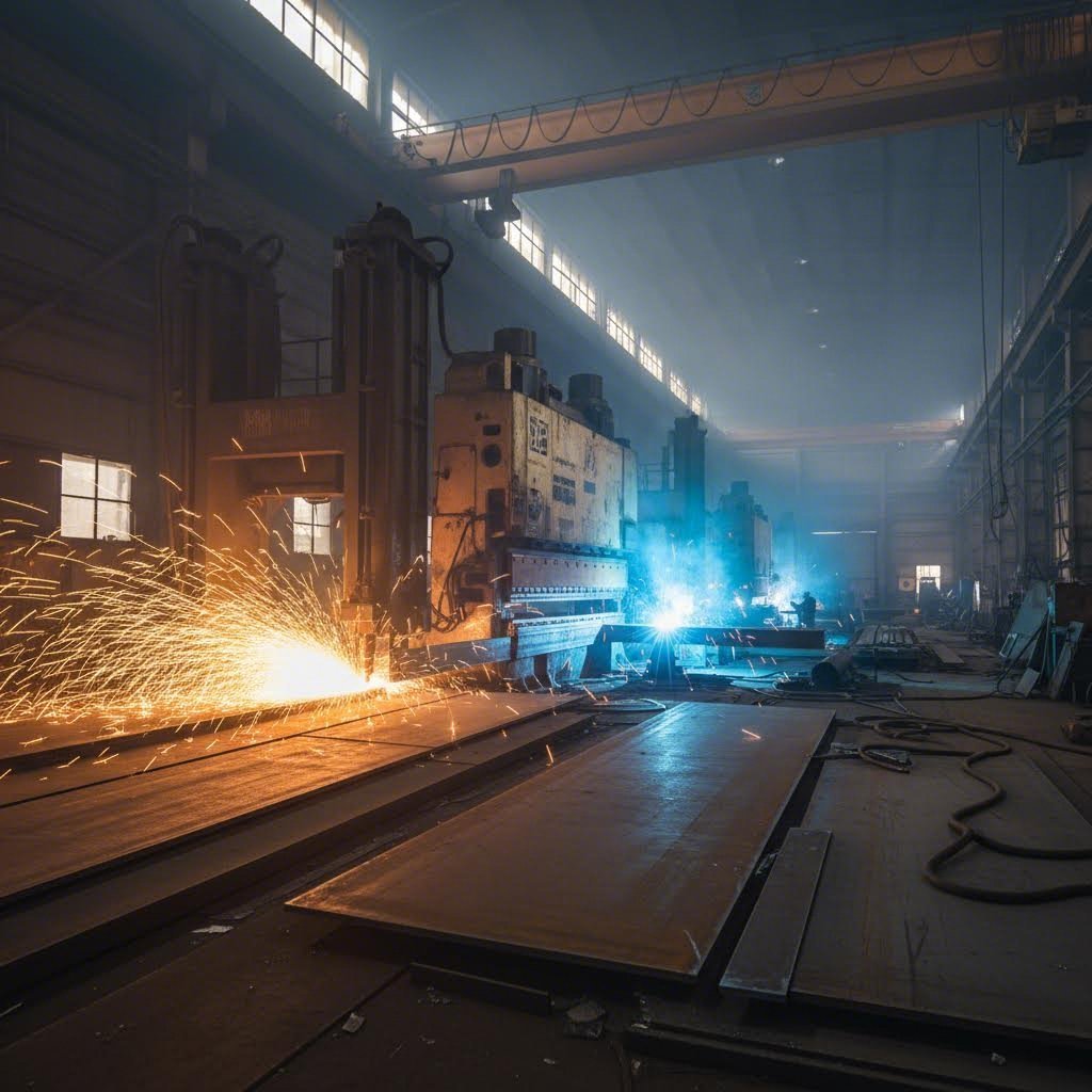
Plate Steel Fabrication Demystified: Cutting, Welding, And Finishing Done Right
What Is Plate Steel Fabrication and Why Thickness Matters
When you're working with heavy structural components, bridges, or industrial machinery, you'll quickly discover that not all steel is created equal. The distinction between a thin metal sheet and a robust steel plate might seem minor on paper, but in the fabrication world, it changes everything about how you cut, form, and weld your material.
Plate steel fabrication refers to the specialized manufacturing processes—including cutting, forming, welding, and finishing—performed on steel products with a thickness of ¼ inch (6mm) or greater. This thickness threshold is what officially distinguishes plate from sheet metal.
What Separates Plate Steel From Sheet Metal
Imagine holding two pieces of steel side by side. One bends easily in your hands; the other feels substantial and rigid. That's the fundamental difference between sheet vs plate steel. According to industry standards, if the thickness measures less than ¼ inch (6mm), you're dealing with sheet metal. Cross that threshold, and you've entered plate territory.
This isn't just an arbitrary classification. Metal Supermarkets notes that sheet metal is typically measured in gauges, while plate steel is measured directly in inches or millimeters. You'll also notice a practical difference in storage—sheet steel comes coiled, while metal plate is stacked flat due to its rigidity.
The plate vs sheet steel distinction matters because each requires fundamentally different fabrication approaches. Sheet metal can be stamped, folded, and manipulated with relatively light equipment. Plate steel demands heavy-duty machinery, specialized cutting systems, and welding procedures designed for thicker cross-sections.
The Thickness Threshold That Changes Everything
Why does that ¼ inch mark carry so much weight in metal fabrication? Consider what happens during common fabrication operations:
- Cutting: Thicker steel plate requires more powerful thermal cutting systems or specialized waterjet equipment to achieve clean edges
- Forming: Bending plate steel demands exponentially more force and careful calculation of springback and minimum bend radius
- Welding: Thicker materials need proper joint preparation, preheat protocols, and multi-pass welding techniques
- Heat management: Plate fabrication involves significant heat-affected zones that must be controlled to prevent distortion
Steel fabrication for plate-thickness materials serves as the backbone of heavy industrial and structural manufacturing. As Service Steel explains, common applications include structural steel beams, ship hulls, heavy machinery components, storage tanks, and bridge construction. These applications demand the strength and durability that only plate steel can provide.
Both sheet metal and steel plate undergo hot rolling during production, where steel slabs are heated and passed through rollers to achieve the desired thickness. However, the processing, handling, and fabrication requirements diverge significantly once you cross into plate territory. Understanding this distinction helps you select the right fabrication methods, equipment, and partners for your project from the very start.
Understanding Plate Steel Grades and Their Fabrication Behavior
So you've got a plate steel project on your hands—but which grade should you choose? Here's where things get interesting. The steel plates you select will directly influence every fabrication decision downstream, from cutting speeds to welding procedures. Pick the wrong grade, and you're looking at cracked welds, failed bends, or components that won't survive their intended service life.
Understanding steel plate grades isn't just academic knowledge—it's the foundation of successful fabrication. Let's break down what you need to know about structural versus specialty grades and how material properties translate into real-world fabrication decisions.
Structural vs Specialty Plate Grades
When fabricators talk about plate steel, they're typically working with three broad categories: structural grades, pressure vessel grades, and specialty plates like abrasion-resistant steels. Each serves distinct purposes and behaves differently under the torch and in the press brake.
Structural steel plates form the workhorses of construction and heavy fabrication. ASTM A36, the most common structural grade, delivers a minimum yield strength of 36,000 psi with tensile strength between 58,000-80,000 psi according to Alro Steel's specifications. You'll find these steel plates for construction everywhere—bridges, buildings, and heavy equipment frames. The beauty of A36? Excellent weldability and formability that make it forgiving for most fabrication shops.
Step up to high-strength low-alloy (HSLA) grades like ASTM A572 Grade 50, and you gain significantly higher strength—50,000 psi minimum yield—while maintaining good fabrication characteristics. These alloy steel plates contain small additions of vanadium or columbium that boost strength without sacrificing weldability.
Pressure vessel quality (PVQ) plates like ASTM A516 Grade 70 are engineered for critical containment applications. With controlled chemistry and mandatory impact testing, these grades ensure reliable performance in tanks, boilers, and process equipment. The trade-off? Tighter fabrication controls and more rigorous inspection requirements.
Abrasion-resistant plates occupy their own category entirely. Grades like AR400, AR450, and AR500 are heat-treated to achieve surface hardness levels that dramatically extend service life in mining, quarry, and material handling applications. Tricon Wear Solutions explains that AR500 typically achieves 470-525 BHN (Brinell Hardness Number), offering exceptional wear resistance—but at significant cost to formability and weldability.
How Material Grade Affects Your Fabrication Approach
Here's where tensile strength, hardness, and chemistry stop being abstract numbers and start dictating your shop floor decisions.
Cutting considerations: Softer structural grades like A36 cut cleanly with plasma or oxy-fuel, requiring minimal edge preparation afterward. Move to AR500 or higher-hardness alloy steel plates, and you'll notice slower cutting speeds and the need for careful heat management to prevent edge cracking. Some fabricators prefer waterjet cutting for hardened plates to eliminate heat-affected zone concerns entirely.
Forming realities: The relationship between hardness and formability is inverse—as one goes up, the other comes down. A36 bends predictably with manageable springback. AR400 still offers reasonable formability despite its 360-444 BHN surface hardness. But AR500? Expect significant resistance and potential cracking during forming operations. Alloyed abrasion-resistant steels represent the evolution of this category, achieving AR500-level hardness with AR400-like formability through advanced metallurgy.
Welding implications: Carbon content and alloy additions directly impact weldability. Low-carbon structural grades rarely need preheat for typical thicknesses. Higher-carbon or hardened grades demand strict preheat protocols, controlled interpass temperatures, and often hydrogen-controlled filler metals to prevent hydrogen-induced cracking. The commodity AR grades, particularly AR500, can be especially prone to cracking during welding if proper procedures aren't followed.
| Grade Designation | Typical Applications | Weldability Rating | Formability Characteristics |
|---|---|---|---|
| ASTM A36 | Buildings, bridges, general structural | Excellent | Excellent—minimal springback, tight bend radii possible |
| ASTM A572 Gr. 50 | Structural applications requiring higher strength | Very Good | Very Good—slightly more springback than A36 |
| ASTM A516 Gr. 70 | Pressure vessels, tanks, boilers | Good | Good—requires attention to bend radius calculations |
| ASTM A514 (Q&T) | Cranes, heavy equipment, high-stress structures | Fair—requires preheat and controlled procedures | Limited—100 ksi yield restricts forming options |
| AR400 | Wear liners, chutes, hoppers | Fair—preheat required, crack-sensitive | Fair—cold forming possible with proper radii |
| AR500 | Severe abrasion applications, targets | Poor—high crack risk, strict controls needed | Poor—minimal cold forming capability |
| 316 Stainless Steel | Corrosive environments, marine, chemical processing | Good—requires proper filler selection | Good—work hardens during forming |
The bottom line? Selecting the right steel plate grade requires balancing service requirements against fabrication capabilities. A plate with incredible wear resistance means nothing if your shop can't weld it successfully, and an easy-to-fabricate grade won't help if it wears out in six months. Understanding how each grade behaves during cutting, forming, and welding allows you to make informed decisions that lead to successful projects—and that knowledge becomes even more critical as we explore the specific cutting methods used in plate fabrication.
Cutting Methods for Plate Steel From Plasma to Waterjet
You've selected your plate grade—now how do you turn that raw steel into precise components? The cutting method you choose affects far more than just separating metal. It determines your edge quality, dimensional accuracy, heat-affected zone characteristics, and ultimately, how much downstream work your parts will need before they're ready for assembly.
Unlike working with thin sheet metal where a die cut machine might handle the job, plate steel demands more powerful thermal or mechanical cutting systems. Each technology brings distinct advantages and trade-offs that make it ideal for specific situations. Understanding why certain methods suit particular applications—not just what they do—helps you make smarter decisions for your fabrication projects.
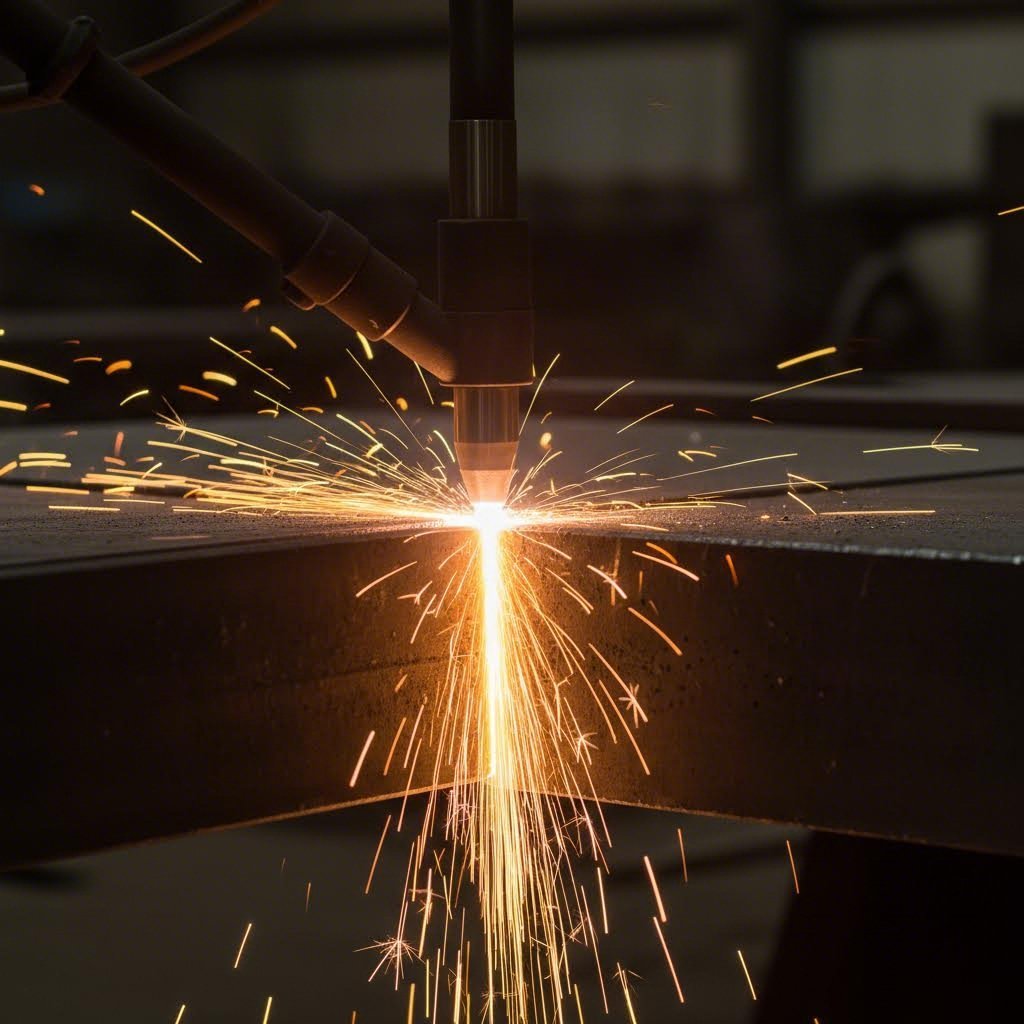
Thermal Cutting Methods for Heavy Plate
When fabricators tackle thick steel plate, thermal cutting methods remain the workhorses of the industry. These processes use heat to sever metal, each with unique characteristics that influence when you'd reach for one over another.
Oxy-fuel cutting stands as the oldest method for cutting mild steel, and it's still going strong for good reason. According to ESAB's technical resources, oxy-fuel torches can handle substantial plate thickness—some systems cut through 36 to 48 inches of steel. The sweet spot? Plates beyond 1 inch thick, where oxy-fuel's cost-effectiveness really shines. The process delivers smooth, square cuts with relatively low equipment costs.
However, oxy-fuel has limitations worth noting. It only cuts ferrous metals (carbon steel), requires preheating before each cut which reduces productivity, and struggles with thinner materials where heat distortion becomes problematic. If you're frequently cutting heavy steel plate above 30mm, oxy-fuel deserves serious consideration. For mixed-thickness work or non-ferrous metals, you'll need to look elsewhere.
Plasma arc cutting offers significantly higher speeds compared to oxy-fuel, making it the popular choice for mild steel plate cutting across a broader thickness range. As SureFire CNC explains, plasma systems deliver both low operating costs and fast cutting speeds, with consumable torch parts and electricity being the primary ongoing expenses.
Optimal edge quality with plasma typically falls in the 1/4 inch to 1.5 inch range. Beyond that, you may see increased edge bevel angle and dross. Modern high-definition plasma systems have improved dramatically, but plasma will always produce some degree of edge imperfection compared to cold-cutting methods. For many industrial applications, this is more than acceptable—especially when you factor in the cost and speed advantages.
Laser cutting brings exceptional precision to plate fabrication, though thickness limits apply. The process works well for mild steel up to around 1.25 inches, excelling in accuracy with narrow kerf width and minimal dross. When you need intricate contours or precise holes, a laser cutter delivers results that other thermal methods simply can't match.
What makes laser cutting particularly valuable is its ability to run unattended for extended periods, enhancing productivity for high-volume operations. The trade-offs include higher equipment and operating costs, plus the need for laser-grade steel and proper gas purity to ensure consistent performance. For precision-critical applications, these investments often pay dividends.
Precision Cutting Technologies Compared
Waterjet cutting occupies a unique position in the metal cutter lineup—it's the only method that introduces no heat into the workpiece. This cold-cutting process uses a high-pressure water stream mixed with abrasive garnet to slice through virtually any material with exceptional accuracy.
Why does zero heat matter so much? Consider the heat-affected zone (HAZ) that thermal cutting creates. This altered metallurgical structure adjacent to the cut edge can affect material properties, cause hardening in certain alloys, and create residual stresses. For hardened plates like AR500, waterjet eliminates concerns about edge cracking or temper loss entirely. The edge smoothness surpasses even laser cutting in many cases.
The downside? Waterjet is both the slowest cutting method and among the most expensive to operate. Garnet abrasive consumption drives significant ongoing costs. But for materials that don't tolerate heat, applications requiring tight tolerances, or mixed-material cutting (imagine needing to know how to cut plexiglass and steel plate on the same machine), waterjet's versatility justifies the investment.
Understanding kerf width matters more than many fabricators realize. Kerf—the width of material removed during cutting—varies significantly between methods:
- Laser: Narrowest kerf (typically 0.006-0.015 inches), ideal for intricate parts with tight nesting
- Plasma: Moderate kerf (0.050-0.150 inches depending on amperage), good balance for general fabrication
- Oxy-fuel: Wider kerf (0.040-0.060 inches), acceptable for structural work
- Waterjet: Varies with material and speed (0.030-0.050 inches typical), highly consistent
Why does this matter downstream? Wider kerf means more material waste and potentially looser tolerances. Narrow kerf allows tighter nesting of parts, reducing material costs on expensive alloy steel plates. For weld-fit applications, consistent kerf width ensures predictable joint geometry.
| Cutting Method | Thickness Range | Cut Quality | Cutting Speed | Heat-Affected Zone | Best Applications |
|---|---|---|---|---|---|
| Oxy-Fuel | 1/4" to 48"+ (mild steel only) | Good on thick plate; poor on thin | Slow to moderate | Large—significant on thinner material | Heavy structural plate, thick carbon steel, multi-torch production |
| Plasma | Gauge to 2"+ (optimal 1/4" to 1.5") | Good to very good in optimal range | Fast | Moderate—manageable above 3mm | General fabrication, mixed thickness work, production volume |
| Laser | Gauge to ~1.25" | Excellent—minimal dross, narrow kerf | Fast on thin; moderate on thick | Small—concentrated but minimal | Precision parts, intricate contours, automated production |
| Waterjet | Virtually unlimited (practical to 8-12") | Excellent—smooth, accurate edges | Slow | None—cold cutting process | Heat-sensitive materials, tight tolerances, mixed materials |
Recent research published in ScienceDirect's engineering journals confirms that optimal cutting process selection depends on evaluating multiple criteria simultaneously—thickness capability alone doesn't tell the whole story. When laser beam cutting was evaluated against expanded criteria including operational costs, edge quality, and material versatility, rankings shifted compared to simpler assessments.
The practical takeaway? Match your cutting method to your specific requirements. Production volume, material grade, thickness range, edge quality needs, and downstream operations all influence the right choice. Many progressive fabrication shops use multiple cutting technologies, leveraging the strengths of each for different applications. As you move from cut parts to forming and bending operations, the quality of your initial cuts directly impacts how smoothly subsequent fabrication steps proceed.
Forming and Bending Thick Steel Plate Successfully
Your plate is cut and ready—now comes the challenge of shaping it. Bending thick steel plate isn't simply a scaled-up version of sheet metal work. When you cross that 1/4 inch thickness threshold, everything changes: the forces involved multiply dramatically, springback becomes a serious engineering consideration, and material grade starts dictating what's physically possible.
Whether you're forming structural brackets, curved tank sections, or heavy equipment components, understanding how thick metal plate behaves under pressure separates successful fabrication from cracked parts and rejected assemblies. Let's explore the fundamental processes and the critical factors that determine whether your bending operations succeed or fail.
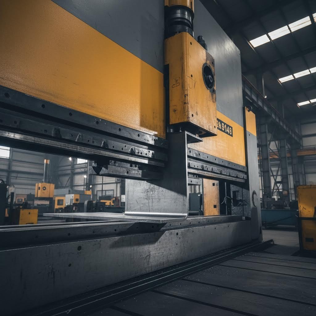
Press Brake Fundamentals for Thick Plate
The press brake remains the workhorse for plate fabrication when you need precise angular bends. But working with thick steel plate demands respect for some fundamental physics that lighter gauge work lets you ignore.
How press brake bending actually works: A punch mounted on the ram descends into a V-shaped die, forcing the plate to conform. In air bending—the most common technique for plate work—the material contacts only the punch tip and die shoulders, creating a bend radius determined primarily by the die opening width rather than the punch radius.
According to ADH Machine Tool's technical resources, this relationship follows predictable rules based on material strength. For mild steel at approximately 60 KSI tensile strength, the resulting internal radius equals roughly 16% of the V-die opening. Stainless steel follows an 18-20% rule due to higher springback, while softer aluminum achieves tighter radii at 12-15% of the die opening.
Tonnage requirements scale exponentially: Doubling your plate thickness doesn't double the required force—it increases geometrically. A press brake that easily handles 1/4 inch formed plate may struggle with 1/2 inch material of the same grade. This is where many shops run into project feasibility issues. Before committing to a design, verify your equipment can actually deliver the tonnage needed.
The general formula for estimating tonnage involves material thickness squared, multiplied by tensile strength, and divided by die opening width. For thick steel plate, always calculate conservatively and confirm capacity before cutting expensive material.
Minimum Bend Radius: The Line You Cannot Cross
Every material has a physical limit—a minimum bend radius below which the outer fibers will crack. Push past this threshold, and you're not forming metal; you're breaking it.
The minimum bend radius depends on three primary factors:
- Material ductility: Softer, more ductile materials accept tighter bends. A36 structural steel bends far more readily than AR500 abrasion-resistant plate.
- Plate thickness: Thicker material requires proportionally larger radii. For plate under 6mm, the minimum radius often equals the thickness itself. For plate between 6-12mm, expect 1.5 times thickness. Beyond 12mm, plan for 2-3 times thickness as your starting point.
- Grain direction: Bending perpendicular to the rolling direction (against the grain) increases cracking risk significantly.
The optimal bend radius—the sweet spot where quality, strength, and efficiency converge—typically occurs when the inside radius approximately equals the material thickness. At this ratio, stress distribution remains uniform, springback stays manageable, and dimensional consistency improves.
Springback: The Invisible Enemy of Accuracy
Bend a piece of thick metal plate to exactly 90 degrees, release the pressure, and watch it spring back to 87 or 88 degrees. This elastic recovery—springback—frustrates fabricators who don't understand or compensate for it.
Springback increases with:
- Higher material yield strength (stainless steel springs back more than mild steel)
- Larger bend radius relative to thickness (the R/T ratio)
- Thinner material relative to die opening
Compensation strategies include over-bending—using a die angle sharper than your target (an 86-degree die for a 90-degree bend) or adjusting CNC press brake depth settings to intentionally exceed the final angle. Modern equipment often incorporates real-time angle measurement and automatic compensation, but understanding the underlying physics helps you troubleshoot when results don't match expectations.
When Roll Forming Makes Sense
Press brakes excel at angular bends, but what about curves? When your plate fabrication project requires cylindrical sections, large-radius arcs, or conical shapes, plate rolling machines become the appropriate choice.
Roll forming feeds flat plate through a series of rollers arranged in a pyramid configuration. By adjusting roller positions and making multiple passes, operators gradually curve the material into the desired radius. This process handles thicker and wider plates than most press brakes can accommodate—a significant advantage for tank fabrication, structural tubes, and architectural applications.
Key roll forming considerations include:
- Material thickness capacity: Plate rolls are specifically designed for heavy material, often handling plates several inches thick
- Minimum diameter limits: Every roll forming machine has a minimum achievable diameter based on roll size—parts requiring very tight curves may not be feasible
- Flat ends: Rolled cylinders typically have flat sections at each end that require additional processing or trimming
- Multiple passes: Unlike press brake bending, roll forming is iterative—achieving precise diameters requires progressive adjustment and measurement
Factors That Determine Forming Method Selection
Choosing between press brake bending, roll forming, or alternative methods depends on several interconnected factors:
- Final geometry: Angular bends favor press brakes; curved sections favor rolling
- Material grade: High-strength or hardened plates may require preheating, wider dies, or larger radii regardless of method
- Production volume: Press brakes offer faster setup for small batches; rolling suits high-volume cylindrical production
- Available equipment tonnage: Projects must fit within your capacity—no amount of technique compensates for insufficient force
- Tolerance requirements: Precision applications may demand specific equipment capabilities or secondary operations
- Surface finish sensitivity: Cosmetic parts may need protective films or specialized tooling to prevent marking
Wilson Tool International notes that thick gauge material is particularly demanding on tooling, with punch radii wearing faster than punch bodies. Replaceable radius punches and induction-hardened surfaces help extend tool life when bending repeatedly takes its toll.
Successfully forming thick steel plate requires balancing material properties, equipment capabilities, and design requirements. When these elements align, plate fabrication produces components that maintain structural integrity while meeting dimensional specifications. When they conflict, the result is scrapped material, damaged tooling, or both. This understanding of forming behavior becomes equally critical as we move into welding operations, where the stresses introduced during bending must be considered alongside the new thermal stresses from joining processes.
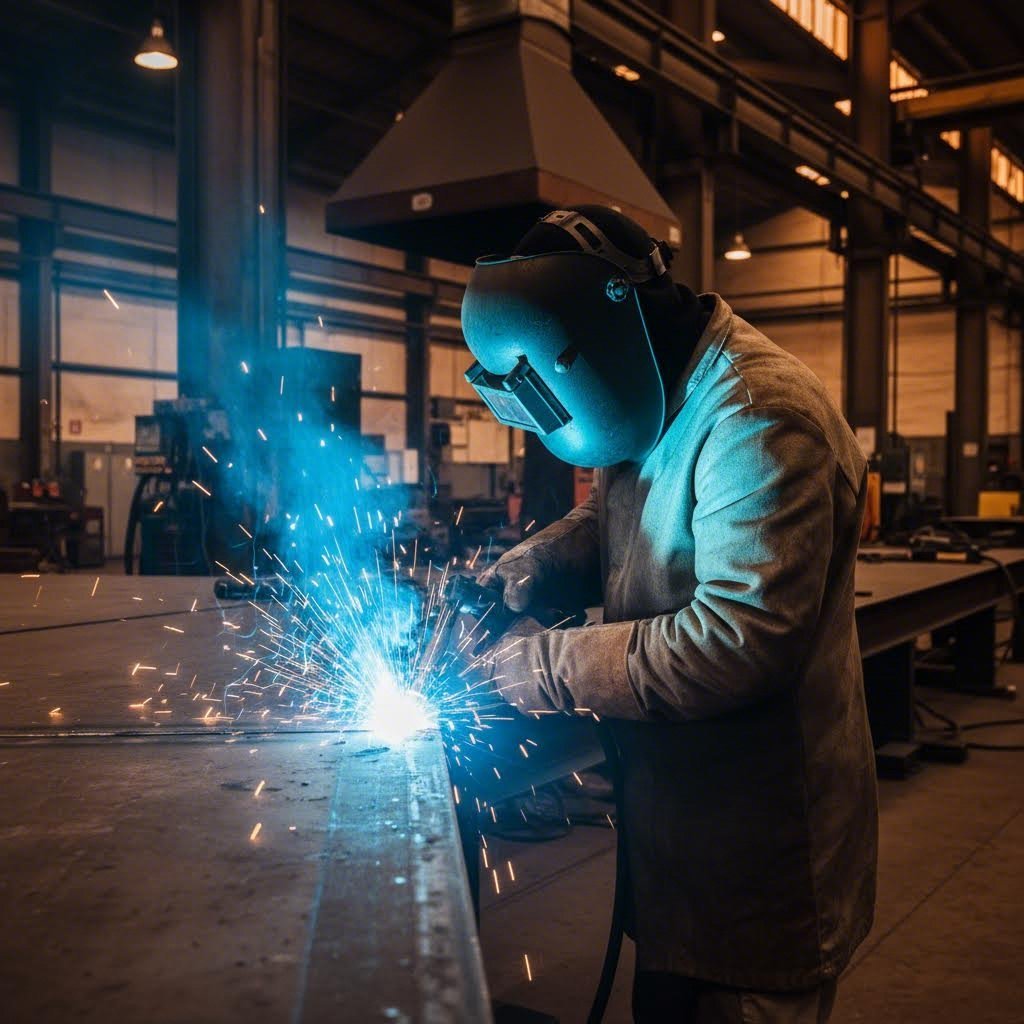
Welding Plate Steel From Preparation to Post-Weld Treatment
Your plates are cut and formed—now comes the moment of truth. Welding thick steel plate isn't simply turning up the amperage and running a bead. The margin for error shrinks dramatically when you're joining material measured in fractions of an inch rather than gauges. Skip the proper preparation steps, and you're gambling with weld integrity, structural performance, and project success.
What separates professional steel plate construction from amateur work? It's the disciplined attention to everything that happens before, during, and after the arc strikes. Let's walk through the critical considerations that ensure your plate welds perform as designed.
Joint Preparation for Structural Plate Welds
As ESAB's welding experts put it: "A weld is only as good as the joint, which makes preparation the key to a quality job." This principle becomes absolutely critical when working with weldable steel plate in structural applications.
Start with contamination removal—and be thorough. Oils, grease, cutting fluids, and lubricants must go first. Use a non-chlorinated chemical cleaner such as acetone, ensuring your solvent won't leave residue that creates harmful vapors during welding. After chemical cleaning, grab a wire brush or grinder to remove rust, scale, mill scale, dirt, paint, and dross from previous cutting operations.
Here's a detail many fabricators overlook: if you're welding stainless steel or aluminum plates, use a dedicated stainless-steel brush or grinding wheel exclusively for these alloys. Using a brush that previously cleaned carbon steel can embed small grains of contaminating material into your base metal—and those contaminants end up in your weld.
Beveling requirements for thick plate: When welding materials over 1/4 inch thick, you'll typically need to bevel the edges to ensure complete joint penetration. For T-joints, bevel one edge to approximately 45 degrees. V-groove joints generally call for about 30 degrees on each side, though actual angles vary based on the specific materials and welding codes you're following.
Don't grind your bevel to a knife-edge—the welding arc will simply blow away that thin material. Instead, leave a "land" of 1/16 to 1/8 inch at the root. This flat section supports the arc's heat and enables proper fusion at the joint root.
- Clean thoroughly: Remove all oils, grease, and cutting fluids with appropriate solvents
- Remove surface contaminants: Grind or brush away rust, scale, paint, coatings, and cutting dross
- Use dedicated tools: Separate brushes and wheels for stainless and aluminum to prevent cross-contamination
- Bevel appropriately: Apply proper joint geometry for your plate thickness and weld type
- Maintain a land: Leave 1/16 to 1/8 inch at the root to support arc penetration
- Control moisture: Bring cold or damp material to room temperature before welding
- Verify fit-up: Check joint alignment and root opening before striking an arc
Preheat and Interpass Temperature Control
Why would you intentionally heat steel before welding it? Because thick, cold plate acts like a massive heat sink, rapidly drawing heat away from your weld zone. This rapid cooling creates several problems: incomplete fusion, lack of penetration, and—most critically—weld cracking from thermal shock.
Preheating serves multiple purposes. It slows the cooling rate, reducing the risk of hydrogen-induced cracking in the heat-affected zone. It helps drive off moisture that might otherwise introduce hydrogen into the weld. And it reduces residual stresses that develop when hot weld metal contracts against cold base material.
When should you preheat? The answer depends on material thickness, carbon equivalent, and ambient conditions. As a general starting point, consider preheating carbon steel plates over 1 inch thick to around 250°F. Higher-carbon grades and crack-sensitive materials like AR500 demand even more attention—some procedures call for preheat temperatures of 300-400°F or higher.
Invest in temp sticks (also called temperature-indicating crayons) to verify your preheat. These specialized markers melt within a 1% range of their stated temperature, giving you reliable confirmation without expensive equipment. Just apply the mark outside the actual weld area to prevent contamination.
Interpass temperature matters equally. This refers to the temperature of the weld area before you start each subsequent pass in a multi-pass weld. Letting thick plate cool too much between passes reintroduces the same cracking risks you addressed with preheat. Most procedures specify both a minimum interpass temperature (to maintain adequate heat) and a maximum (to prevent overheating and metallurgical damage).
MIG vs TIG Welding: Choosing the Right Process for Plate Work
When comparing mig vs tig welding for plate steel applications, the choice often comes down to production requirements, material thickness, and required weld quality.
MIG welding (Gas Metal Arc Welding) dominates heavy plate fabrication for compelling reasons. According to American Torch Tip's technical analysis, MIG excels on thicker materials because the continuously fed wire acts as both electrode and filler. This allows fusion of thick sections without heating them completely through—a critical advantage on heavy plate where heat management already challenges fabricators.
The tig vs mig welding debate also involves speed. MIG guns run continuously for extended periods, making them dramatically more productive for structural plate work. For large industrial operations requiring high deposition rates, MIG is the clear choice. The process also handles challenging positions—overhead, vertical, horizontal—more easily than TIG, with the shielding gas protecting the weld pool even when gravity works against you.
TIG welding (Gas Tungsten Arc Welding) serves different purposes in plate fabrication. When you need exceptional precision, minimal spatter, and the highest quality welds on visible or critical joints, TIG delivers. The process shines on thinner materials, root passes, and situations requiring meticulous control—though it requires significantly more operator skill and takes longer than MIG.
For most steel plate construction applications, fabricators use MIG for production welding and reserve TIG for specialized situations. Root passes on critical pipe joints, precision repair work, and cosmetic welds where appearance matters might justify the slower TIG process. Volume production of structural plate assemblies? MIG wins every time.
Interestingly, while aluminum welding often favors TIG for its precision, MIG remains practical for thicker aluminum plate sections where deposition rate matters more than absolute cosmetic perfection.
Filler Metal Selection and Post-Weld Considerations
Matching your filler metal to the base material isn't optional—it's fundamental to weld integrity. For standard structural steel like A36, common choices include E7018 electrodes for stick welding or ER70S-6 wire for MIG. Higher-strength plates require corresponding higher-strength fillers.
For crack-sensitive materials, consider low-hydrogen filler metals that minimize hydrogen pickup in the weld deposit. Proper storage of electrodes—keeping them dry and at appropriate temperatures—prevents moisture absorption that would defeat this protection.
Post-weld heat treatment (PWHT) enters the picture for critical applications, high-strength steels, or code-mandated situations. Controlled heating after welding relieves residual stresses, tempers hard zones, and can improve weld toughness. PWHT requirements vary dramatically based on material, thickness, and application—always consult applicable welding codes like AWS D1.1 or project-specific procedures.
Even when full PWHT isn't required, slow cooling matters. Throwing a tarp over freshly welded thick plate or using insulation blankets slows the cooling rate and reduces residual stress development. This simple step prevents many cracking problems that appear hours after welding appears complete.
The welding procedures that produce sound, strong joints in plate steel don't happen by accident—they result from disciplined preparation, proper thermal management, appropriate process selection, and attention to post-weld handling. With these fundamentals in place, you're ready to address the quality control measures and defect prevention strategies that ensure your fabricated components perform as designed.
Preventing Defects and Ensuring Quality in Plate Fabrication
You've cut, formed, and welded your structural steel plate—but how do you know it's actually right? Quality control in plate steel fabrication isn't a final inspection stamp at the end of the line. It's a continuous process woven throughout every operation, catching problems before they become expensive failures in the field.
The challenges unique to heavy plate work—heat distortion, warping, dimensional drift—demand proactive strategies rather than reactive fixes. Let's explore how experienced steel fabricators prevent defects and maintain the tight tolerances that structural applications demand.
Controlling Heat Distortion in Plate Work
Here's a frustrating reality: every thermal operation you perform on steel plate wants to distort it. Cutting, welding, even stress relieving—each introduces heat that expands metal unevenly, and that uneven expansion creates warping, bowing, and angular distortion that can push your components out of spec.
According to TWI Global's technical resources, controlling distortion starts with smart assembly techniques before welding even begins:
- Tack welding strategy: Proper tack placement sets and maintains joint gaps while resisting transverse shrinkage. Too few tacks? The joint progressively closes as welding proceeds. Use a back-step sequence—tack one end, then work backward—to maintain uniform root gaps along long seams.
- Back-to-back assembly: Tack or clamp two identical components together before welding. This balances the heat input around the neutral axis of the combined assembly, and both parts help restrain each other from distorting.
- Longitudinal stiffeners: For butt-welded thin plate structures prone to bowing, welding flat or angle stiffeners along each side of the seam prevents longitudinal distortion.
The welding sequence itself matters enormously. For long welds, never complete the entire seam in one direction. Back-step welding—depositing short adjacent weld lengths in the opposite direction to overall progression—controls heat buildup. Skip welding accomplishes similar results by laying short weld lengths in predetermined, evenly spaced sequences along the seam.
The general principle? Deposit weld metal as quickly as possible using the fewest runs to fill the joint. MIG outperforms stick welding for distortion control because of its higher deposition rates. Mechanised welding systems offer even greater consistency, making presetting and other compensation techniques more reliable.
Quality Checkpoints Throughout Fabrication
Catching problems early saves exponentially more than finding them at final inspection. Industry best practices integrate quality verification at every fabrication stage—not just the end.
Material verification happens first. Before cutting begins, confirm that mill test reports match the steel plate thickness and grade specified for your project. Standard steel plate dimensions should align with drawings, and heat numbers on main members must trace back to certified documentation. For structural steel and plate fabrication, this traceability isn't optional—it's a code requirement.
In-process inspection continues throughout fabrication. Cutting operations require verification of edge quality, dimensional accuracy, and acceptable heat-affected zone characteristics. Forming operations demand measurement of bend angles and radii against tolerances. Welding inspection—both visual and non-destructive testing—validates joint integrity before parts move downstream.
The Colorado Department of Transportation's fabrication inspection guidelines outline the rigorous approach required for structural steel plate work: review of Welding Procedure Specifications (WPS) and Procedure Qualification Records (PQR) before fabrication begins, verification of welder qualifications, daily in-process visual inspection, and 100% final weld examination for all completed joints.
Non-destructive testing (NDT) provides the subsurface verification that visual inspection cannot. Common methods include:
- Magnetic particle inspection: Detects surface and near-surface discontinuities in ferromagnetic materials—particularly effective for evaluating weld terminations and repair locations
- Ultrasonic testing: Uses sound waves to identify subsurface defects, essential for verifying complete joint penetration in critical welds
- Radiographic inspection: X-ray examination reveals internal porosity, inclusions, and lack of fusion
Dimensional verification using coordinate measuring machines (CMMs), laser scanning, or traditional measurement tools confirms that steel plate dimensions remain within tolerance after thermal operations. Statistical process control (SPC) helps detect manufacturing variations early, before they cascade into rejected assemblies.
Industry Standards That Govern Plate Fabrication
Quality in structural steel and plate fabrication isn't subjective—it's defined by established standards and certification requirements that specify exactly what's acceptable and what isn't.
AWS D1.5 Bridge Welding Code governs welding on structural steel bridges, specifying everything from welder qualification requirements to acceptable discontinuity limits. For general structural work, AWS D1.1 Structural Welding Code—Steel provides the framework. These documents define essential variables for welding procedures, required inspection frequencies, and acceptance criteria for completed welds.
ASTM specifications establish material requirements. ASTM A36 defines standard structural steel properties; ASTM A572 covers high-strength low-alloy plates; ASTM A516 governs pressure vessel quality material. Each specification includes chemical composition limits, mechanical property requirements, and testing protocols that certified steel fabricators must verify.
Quality management certifications like ISO 9001 and industry-specific standards like IATF 16949 (for automotive applications) demonstrate that fabrication shops maintain documented quality systems. AISC certification confirms that structural steel fabricators meet American Institute of Steel Construction requirements for personnel, equipment, and procedures.
Quality Control Checklist for Plate Fabrication Projects
Implementing systematic quality control requires documented checkpoints throughout the fabrication workflow. The following checklist captures critical verification steps that experienced fabricators integrate into every plate project:
- Pre-fabrication review: Verify shop drawings against design documents; confirm material grades, steel plate dimensions, and weld symbols; review applicable codes and specifications
- Material receipt inspection: Match heat numbers to certified mill test reports; verify steel plate thickness, grade, and condition; confirm domestic origin if required
- Cutting verification: Inspect edge quality for acceptable surface finish and absence of cracks; measure dimensional accuracy; verify hardness on thermal-cut edges of tension members
- Forming inspection: Measure bend angles and radii against tolerances; inspect for surface cracking at bend locations; verify dimensional accuracy after springback
- Pre-weld verification: Confirm joint fit-up geometry; verify base metal preparation and cleanliness; check preheat temperature with temp sticks; validate welder qualifications for the specific procedure
- In-process weld inspection: Monitor welding parameters against WPS limits; verify interpass temperatures; inspect each pass for visible defects before depositing subsequent layers
- Final weld visual inspection: Examine 100% of completed welds for profile, undercut, porosity, cracks, and proper termination; verify welder identification marks
- Non-destructive testing: Perform required NDT per specification—magnetic particle, ultrasonic, or radiographic—and document results against acceptance criteria
- Dimensional verification: Measure critical dimensions after welding; check for distortion against tolerance limits; verify standard steel plate dimensions match drawing requirements
- Surface preparation and coating inspection: Verify surface cleanliness to specified standards; measure coating thickness; inspect for coverage and adhesion
- Final documentation: Compile mill test reports, weld maps, NDT reports, and dimensional records; obtain required quality certifications before release
The investment in systematic quality control pays dividends throughout the project lifecycle. Components that leave the fabrication shop verified and documented arrive at the job site ready for installation—not for rework that delays schedules and inflates costs. This attention to quality during fabrication sets the stage for the final critical step: surface finishing and corrosion protection that ensures your plate steel components perform for decades in service.

Surface Finishing and Corrosion Protection for Plate Steel
Your plate steel components are cut, formed, welded, and inspected—but the job isn't finished. Without proper surface treatment, even the strongest structural steel plate becomes vulnerable to the relentless attack of moisture, chemicals, and atmospheric corrosion. The finish you apply determines whether your fabrication lasts decades or deteriorates within years.
Here's what many fabricators overlook: surface finishing isn't just about appearance. It's the final defense system that protects your investment in material, labor, and precision fabrication. Let's explore how to prepare surfaces properly and select the right protective finish for your application.
Surface Prep Before Coating Application
Every coating system—whether powder coat, galvanizing, or paint—shares one non-negotiable requirement: the surface must be properly prepared. As the American Galvanizers Association emphasizes, preparation is crucial to ensuring effective adhesion and long-term performance.
What does proper preparation involve? Start by removing all contaminants that would interfere with coating adhesion:
- Mill scale: That blue-gray oxide layer formed during hot rolling may look protective, but it flakes off over time—taking your coating with it
- Rust and corrosion products: Even light surface rust creates a weak boundary layer between steel and finish
- Oils and greases: Cutting fluids, forming lubricants, and handling marks all prevent proper bonding
- Weld spatter and slag: These irregular deposits create coating thickness variations and adhesion failures
Abrasive blasting remains the gold standard for surface preparation on heavy plate. Unlike a stainless steel sheet that might accept chemical cleaning alone, thick structural plate typically requires mechanical profiling to create the anchor pattern coatings need to grip. Blast cleaning to SSPC-SP6 (Commercial Blast) or SSPC-SP10 (Near-White Blast) standards removes contamination while creating the surface roughness that enhances adhesion.
The window between surface preparation and coating application matters critically. Once you've exposed clean steel, oxidation begins immediately. Most specifications require coating within hours—not days—of blasting. In humid environments, that window shrinks further. Plan your workflow so prepared surfaces move directly to coating without sitting exposed.
Protective Finishes for Long-Term Performance
Selecting the right finish depends on your service environment, aesthetic requirements, and budget constraints. Each major finishing system offers distinct advantages for plate steel applications.
Hot-dip galvanizing provides exceptional corrosion protection by metallurgically bonding zinc to steel. When the fabricated plate is immersed in molten zinc at approximately 840°F, the zinc reacts with steel to form intermetallic layers topped by pure zinc. This coating doesn't just sit on the surface—it becomes part of the steel itself.
Galvanizing excels in outdoor structural applications, marine environments, and anywhere components face continuous moisture exposure. The zinc coating sacrificially protects steel—even if scratched, the surrounding zinc corrodes preferentially, protecting exposed steel at damage sites. According to Keystone Koating's technical comparison, galvanized sheet metal and plate can withstand decades of atmospheric exposure before requiring maintenance.
The limitation? Galvanizing produces only a metallic silver-gray finish. If color or aesthetics matter, you'll need additional treatment.
Powder coating delivers the color flexibility and durability that galvanizing lacks. This process applies electrostatically charged powder particles to grounded steel surfaces, then cures the coating in ovens at temperatures typically between 350-450°F. The result is a tough, uniform finish available in virtually unlimited colors and textures.
Modern powder coat formulations match or exceed traditional liquid paints for corrosion resistance. Super durable powders specifically engineered for exterior exposure resist UV degradation and chalking far longer than standard formulations. For architectural applications, equipment enclosures, or any situation demanding both protection and appearance, powder coating services provide an excellent solution.
The powder coating process also offers environmental advantages—no solvents, virtually no waste, and overspray can be collected and reused. For fabricators concerned about emissions compliance, this matters increasingly.
Duplex systems—galvanizing followed by powder coating or paint—combine the benefits of both approaches. You gain galvanizing's sacrificial protection plus powder coating's color options and UV resistance. This combination proves particularly valuable for highway structures, architectural steelwork, and components requiring both maximum protection and specific aesthetics.
However, duplex systems require careful surface preparation between coating layers. Galvanized surfaces need profiling—typically by sweep blasting at 30-60 degree angles—to create adhesion for topcoats. The ASTM D6386 specification provides detailed guidance for preparing galvanized steel for paint.
Industrial paint systems remain appropriate for many plate fabrication applications, particularly field-applied coatings and touch-up work. Multi-coat systems typically include zinc-rich primers, intermediate barrier coats, and topcoats selected for the specific exposure environment. While requiring more application labor than powder coating, paint systems offer flexibility for complex geometries and field conditions.
Matching Finish to Application
Which finish makes sense for your project? Consider these factors:
- Hot-dip galvanizing: Ideal for structural steel, outdoor equipment, agricultural machinery, marine components, and any application prioritizing corrosion protection over appearance
- Powder coating: Best for equipment housings, architectural metalwork, consumer products, and applications requiring specific colors or textures
- Duplex systems: Recommended for bridges, transmission structures, architectural steel in corrosive environments, and projects demanding both maximum protection and aesthetic requirements
- Industrial paint: Appropriate for field-applied coatings, large structures too big for dip tanks or ovens, and applications requiring specialized chemical resistance
Surface condition at coating time directly affects coating longevity. A perfectly applied finish over poorly prepared steel fails prematurely—not from coating deficiency, but from adhesion breakdown at the contaminated interface. The investment in proper preparation pays dividends throughout the component's service life.
While anodizing and anodized aluminum finishes serve lightweight alloys beautifully, these electrochemical processes don't apply to steel plate. Stick with zinc-based galvanizing, organic coatings like powder coat and paint, or combination systems for your plate steel fabrication projects.
With surface finishing complete, your fabricated plate steel components are ready for service—protected against corrosion, meeting aesthetic requirements, and prepared to perform for their intended lifespan. But getting from design concept to finished component requires understanding the complete fabrication workflow, where coordination between engineering, procurement, and shop floor execution determines project success.
The Complete Plate Fabrication Workflow From Design to Delivery
You've mastered the individual operations—cutting, forming, welding, finishing—but how do they come together into a seamless project? The difference between a fabrication shop that delivers on time and one that constantly scrambles lies not in equipment alone, but in how effectively the entire workflow connects from initial design through final shipment.
Whether you're working with a local metal fab operation or coordinating with a specialized steel plate fabricator handling heavy plate fabrication, understanding this complete lifecycle helps you anticipate challenges, communicate requirements clearly, and keep your project on track.
From CAD Design to Shop Floor Execution
Every plate fabrication project begins with engineering drawings—but getting from that digital file to physical components involves more complexity than many customers realize.
Modern sheet metal fabrication and plate work relies heavily on Computer-Aided Design (CAD) systems that do far more than create pretty pictures. According to VICLA's technical resources, CAD software enables designers to create custom designs that are accurate, repeatable, and scalable from prototyping to mass production. The procedure includes specific data—dimensions, material properties, tolerances—that thoroughly outline how to transform a design into a tangible product.
What makes CAD particularly valuable for plate work?
- Precision and error reduction: CAD systems dramatically reduce human error, allowing machinery to fabricate items seamlessly while avoiding resource waste from flawed designs
- Virtual testing: Designers can simulate real-world variables and test designs before cutting expensive material—if something needs changing, modifications happen digitally rather than on scrapped steel
- Documentation integrity: All design data saves easily for future reference, reducing communication errors and enabling team members on the shop floor to receive accurate information about critical features
- Visualization capability: 3D visualization allows testing how well designs work before spending money on physical prototypes
The transition from CAD to production involves generating nested cutting programs, developing forming sequences, creating welding procedure specifications, and establishing inspection checkpoints. For structural steel & plate fabrication projects, this programming stage directly impacts material utilization, production efficiency, and ultimately, your project cost.
Design for Manufacturability: Where Smart Projects Begin
Here's where many projects go wrong before fabrication even starts. A design that looks perfect on screen may be impractical, expensive, or impossible to manufacture efficiently. Design-for-manufacturability (DFM) bridges this gap by engineering products specifically to facilitate the manufacturing process.
As Dalsin Industries explains, DFM delivers multiple benefits: reduced costs, problem identification early in the design phase (the least expensive place to address challenges), and resolution of factors affecting manufacturability—material type and thickness, dimensional tolerances, and secondary processing requirements.
What does DFM look like for plate fabrication specifically?
- Bend radius optimization: Designing bends that work with available tooling rather than requiring custom dies
- Weld access considerations: Ensuring welders can physically reach joint locations with proper torch angles
- Nesting efficiency: Designing parts that nest together on standard plate sizes, minimizing scrap
- Tolerance rationalization: Specifying tight tolerances only where functionally necessary, allowing economical production elsewhere
- Material grade selection: Choosing grades that balance performance requirements with fabrication characteristics
Early collaboration between designers and fabricators prevents costly issues that surface later. When engineering teams consult with fabrication shops near me during the design phase rather than after drawings are finalized, they catch problems when changes cost hours rather than weeks. Manufacturers like Shaoyi (Ningbo) Metal Technology demonstrate this value through comprehensive DFM support and rapid quote turnaround—their 12-hour response time and 5-day prototyping capability for automotive structural components shows how integrated design-fabrication collaboration accelerates projects.
Project Planning for Plate Fabrication Success
Sound complex? It doesn't have to be—but effective project planning requires understanding what drives lead times and where bottlenecks typically occur.
Material availability often determines project timelines more than fabrication capacity. Standard structural grades like A36 typically stock readily, but specialty alloys, unusual thicknesses, or large quantities may require mill orders with lead times measured in weeks. For heavy plate fabrication projects requiring non-standard dimensions, early material procurement becomes critical path.
According to The Fabricator's industry analysis, scheduling challenges in custom fabrication often stem from lack of good information. When shops operate with inaccurate data about material availability, equipment capacity, or actual processing times, on-time delivery suffers. The publication notes that average on-time delivery across the industry has hovered between 77% and 88% for the past decade—a sobering reminder that schedule reliability requires active management.
Capacity constraints shift throughout any fabrication facility. One week, the laser backlog creates delays; the next, welding becomes the bottleneck. Experienced project managers understand these dynamics and sequence work accordingly. For multi-operation plate projects, the critical path may run through different departments at different phases.
Quality verification stages add time but prevent far greater delays from rejected components. Building inspection points into project schedules—rather than treating them as afterthoughts—keeps projects moving without sacrificing quality.
The Order-to-Delivery Workflow
How does a typical plate fabrication project flow from initial inquiry to shipped components? Understanding this sequence helps you plan effectively and communicate with your steel plate fabricator at appropriate checkpoints.
- Inquiry and quotation: You submit drawings or specifications; the fabricator evaluates material requirements, processing steps, and capacity to develop pricing and lead time estimates
- Order entry and review: Upon order placement, engineering reviews drawings for manufacturability, develops routings, and identifies any clarification needs
- Material procurement: Standard materials release from inventory; specialty items trigger purchase orders to mills or service centers
- Production scheduling: Jobs enter the queue based on due dates, material availability, and capacity constraints across cutting, forming, welding, and finishing operations
- Fabrication execution: Parts progress through cutting, forming, welding, and finishing operations with in-process quality checks at each stage
- Final inspection and documentation: Completed assemblies undergo dimensional verification, NDT if required, and documentation compilation
- Packaging and shipment: Components are protected for transit and shipped via appropriate carriers
Throughout this workflow, communication matters. Changes in customer requirements, material delays, or discovered fabrication challenges all require timely information exchange. The best fabrication partnerships maintain transparency about project status rather than surprising customers with delays at shipment time.
Scaling From Prototype to Production
Many plate fabrication projects begin with prototype quantities before scaling to production volumes. This transition requires planning that accounts for differences between one-off and repeat manufacturing.
Prototype fabrication often accepts manual processes, hand-fit welding, and individual part handling that would be uneconomical at volume. Moving to production typically involves developing fixtures, optimizing nesting patterns, qualifying welding procedures for consistency, and establishing inspection protocols that scale efficiently.
The gap between prototype success and production readiness catches many projects. A part that a skilled craftsman hand-fabricated perfectly may prove difficult to reproduce consistently across dozens or hundreds of units. DFM principles applied during initial design help, but production planning must still address tooling, fixturing, and process standardization.
For automotive applications where chassis, suspension, and structural components demand both precision and volume, finding fabrication partners with capabilities spanning prototyping through automated mass production becomes essential. IATF 16949 certification—the automotive industry's quality management standard—signals that a fabricator has systems in place to maintain quality at production scale.
With workflow fundamentals understood, the final piece of successful plate fabrication involves selecting the right partner—a decision that affects every aspect of your project from quote accuracy through delivered quality. Let's examine the criteria that matter most when evaluating fabrication capabilities.
Choosing the Right Plate Steel Fabrication Partner
You've learned the technical fundamentals—cutting methods, forming considerations, welding procedures, quality requirements. But here's the reality: even perfect knowledge can't compensate for partnering with the wrong fabricator. Your steel plate fabrication project's success ultimately depends on finding a shop with the right combination of equipment, expertise, and quality systems to deliver what you need.
Whether you're searching for metal fabricators near me or evaluating specialized plate metal fabrication suppliers across the country, the evaluation criteria remain consistent. Let's examine what separates capable partners from those who'll leave you scrambling for alternatives mid-project.
Equipment Capabilities That Matter for Your Project
Not every fabrication shop can handle every project. Before committing, verify that your potential partner actually possesses the equipment capacity your work demands.
According to Kloeckner Metals' fabricator evaluation guide, you'll want to assess both capability and availability. A company may have impressive equipment, but if that equipment is committed to other clients, your project still won't get done on time. Ask specifically about current utilization and realistic scheduling for your project scope.
For structural steel and plate work, critical equipment considerations include:
- Cutting capacity: What thickness range can they cut? Do they have multiple cutting technologies (plasma, oxy-fuel, waterjet, laser) to match the optimal process to your material and tolerance requirements?
- Forming equipment: What's the maximum tonnage on their press brakes? Can their plate rolls handle your diameter and thickness specifications?
- Welding capabilities: Do they have qualified welders for your required procedures? What positions and material combinations can they certify?
- Material handling: Can they lift, position, and manipulate your component sizes safely and efficiently?
Don't rely solely on brochures and websites. Request a facility tour if possible. Walking through the shop reveals whether equipment is well-maintained, organized, and actually capable of handling your work. You'll also gauge whether the facility runs professionally or struggles with disorganization that often signals deeper operational problems.
Certifications and Quality Standards to Verify
Certifications tell you something important: a third party has verified that this fabricator maintains documented quality systems and follows established procedures. For structural steel plate fabrication, certain certifications are non-negotiable depending on your application.
IATF 16949 certification matters critically for automotive supply chain work. This standard, built on ISO 9001 foundations but tailored specifically for automotive manufacturing, signals that a fabricator understands the rigorous quality expectations of automotive OEMs. The certification covers everything from documented procedures to defect prevention and continuous improvement.
As Xometry explains, IATF 16949 is a binary system—a company is either certified or not. When certification is awarded, it signifies the organization has met requirements proving their ability and commitment to limit defects and reduce waste. For chassis, suspension, and structural components where plate steel is common, this certification provides essential assurance.
Other relevant certifications include:
- ISO 9001: The foundational quality management system standard applicable across industries
- AWS certifications: Welding procedure and personnel qualifications per American Welding Society standards
- AISC certification: American Institute of Steel Construction certification for structural steel fabricators
- ASME stamps: Required for pressure vessel fabrication work
Beyond certifications, evaluate the fabricator's actual quality practices. Request examples of past work in applications similar to yours. Ask for references from customers with comparable requirements. A reputable fabricator won't hesitate to connect you with satisfied clients who can speak to their real-world performance.
Production Flexibility: From Prototyping to Volume
Your project needs may evolve. That initial prototype could become a production run of hundreds or thousands. Can your fabrication partner scale with you?
Some shops excel at one-off custom work but struggle with production consistency. Others focus on high-volume manufacturing but can't efficiently handle prototype quantities. The ideal partner demonstrates capability across this spectrum—rapid prototyping for development phases, then seamless transition to automated mass production as volumes increase.
For automotive structural components, this flexibility proves especially valuable. Companies like Shaoyi (Ningbo) Metal Technology exemplify this approach, offering 5-day rapid prototyping alongside automated mass production capabilities. Their IATF 16949 certification, combined with comprehensive DFM support and 12-hour quote turnaround, demonstrates the kind of integrated capability that keeps automotive supply chains moving efficiently.
Evaluate production flexibility by asking:
- What's your typical turnaround for prototype quantities?
- How do you transition from prototype approval to production runs?
- What automation exists for repeat production work?
- How do you maintain quality consistency across varying volumes?
Essential Questions to Ask Potential Fabrication Partners
Before committing to any metal fabrication near me or distant supplier, work through these critical evaluation questions:
- Experience verification: Have you completed projects similar to mine in material grade, thickness, and complexity? Can you provide references?
- Capacity confirmation: Do you have the equipment capacity and workforce availability to meet my timeline?
- Quality documentation: What certifications do you hold? How do you document and verify quality throughout fabrication?
- Communication protocols: Who will be my primary contact? How will you keep me informed of project status and any issues?
- DFM support: Do you offer design-for-manufacturability review? Will you identify potential fabrication challenges before production begins?
- Subcontracting practices: Will you complete all work in-house, or do you subcontract certain operations? If so, who are your subcontractors?
- Inspection capabilities: What non-destructive testing can you perform? Do you have in-house dimensional verification equipment?
- Safety record: What's your safety history? Have you had recent OSHA citations?
- Pricing transparency: How do you structure quotes? What's included, and what might trigger additional charges?
- Lead time reliability: What's your on-time delivery rate? How do you handle schedule conflicts or delays?
Making Your Final Decision
Selecting the right structural steel plate fabrication partner involves balancing multiple factors. The lowest price rarely correlates with the best value—especially when missed deadlines, quality issues, or communication failures create downstream problems that dwarf any initial savings.
Prioritize fabricators who demonstrate genuine understanding of your requirements, maintain appropriate certifications for your application, and communicate transparently throughout the evaluation process. The questions they ask you often reveal as much as the answers they provide—engaged partners want to understand your project thoroughly before committing to deliverables.
For plate metal fabrication projects where quality, timing, and technical capability all matter, investing time in thorough partner evaluation pays dividends throughout your project—and establishes relationships that serve you well on future work. The fabrication expertise you've gained through understanding cutting, forming, welding, and finishing processes now equips you to have informed conversations with potential partners and recognize whether their capabilities truly match your needs.
Frequently Asked Questions About Plate Steel Fabrication
1. What kind of steel is plate steel?
Plate steel is defined as steel sheet measuring 6mm (1/4 inch) or thicker, measured in inches rather than gauges. It includes low, medium, and high carbon steel plates, with common grades like ASTM A36 for structural applications, A572 for high-strength needs, and specialty plates like AR400/AR500 for abrasion resistance. Higher carbon content increases strength and hardness but affects weldability and formability.
2. How are steel plates manufactured?
Steel plates are primarily manufactured through hot rolling, where steel slabs are heated until malleable and passed through rollers to achieve desired thickness. Heavy plate fabrication involves additional processes including quenching and tempering—heating rolled plates 30-40 degrees above critical temperature, then rapid water spray cooling to convert austenite to martensite phase, creating harder, stronger plates for demanding applications.
3. What cutting methods work best for plate steel fabrication?
Four primary cutting methods serve plate steel: oxy-fuel cutting excels for plates over 1 inch thick with low equipment costs; plasma cutting offers faster speeds for 1/4 to 1.5 inch material; laser cutting delivers precision for plates up to 1.25 inches; and waterjet cutting provides heat-free cutting for any thickness without affecting material properties. Selection depends on thickness, tolerance requirements, and material grade.
4. Why is preheat important when welding thick steel plate?
Preheating thick steel plate prevents weld defects by slowing cooling rates, reducing hydrogen-induced cracking risk, driving off moisture, and minimizing residual stresses. Cold thick plate acts as a heat sink, rapidly drawing heat from the weld zone and causing incomplete fusion or cracking. Carbon steel plates over 1 inch typically require preheat to 250°F, with higher temperatures for crack-sensitive materials like AR500.
5. What certifications should a plate steel fabricator have?
Key certifications include IATF 16949 for automotive supply chain work, ISO 9001 for quality management systems, AWS certifications for welding procedures and personnel, and AISC certification for structural steel fabricators. For pressure vessel work, ASME stamps are required. These certifications verify documented quality systems, trained personnel, and adherence to industry standards—essential for structural steel plate fabrication projects.