 Small batches, high standards. Our rapid prototyping service makes validation faster and easier —

Sheet Metal Industrial Secrets: 9 Decisions That Make Or Break Projects

What Makes Sheet Metal Essential for Industrial Manufacturing
When you're sourcing materials for automotive chassis, HVAC systems, or precision enclosures, understanding exactly what qualifies as sheet metal becomes the foundation of every smart manufacturing decision. But here's the thing: not every flat piece of steel or aluminum falls into this category. So what is sheet metal, really?
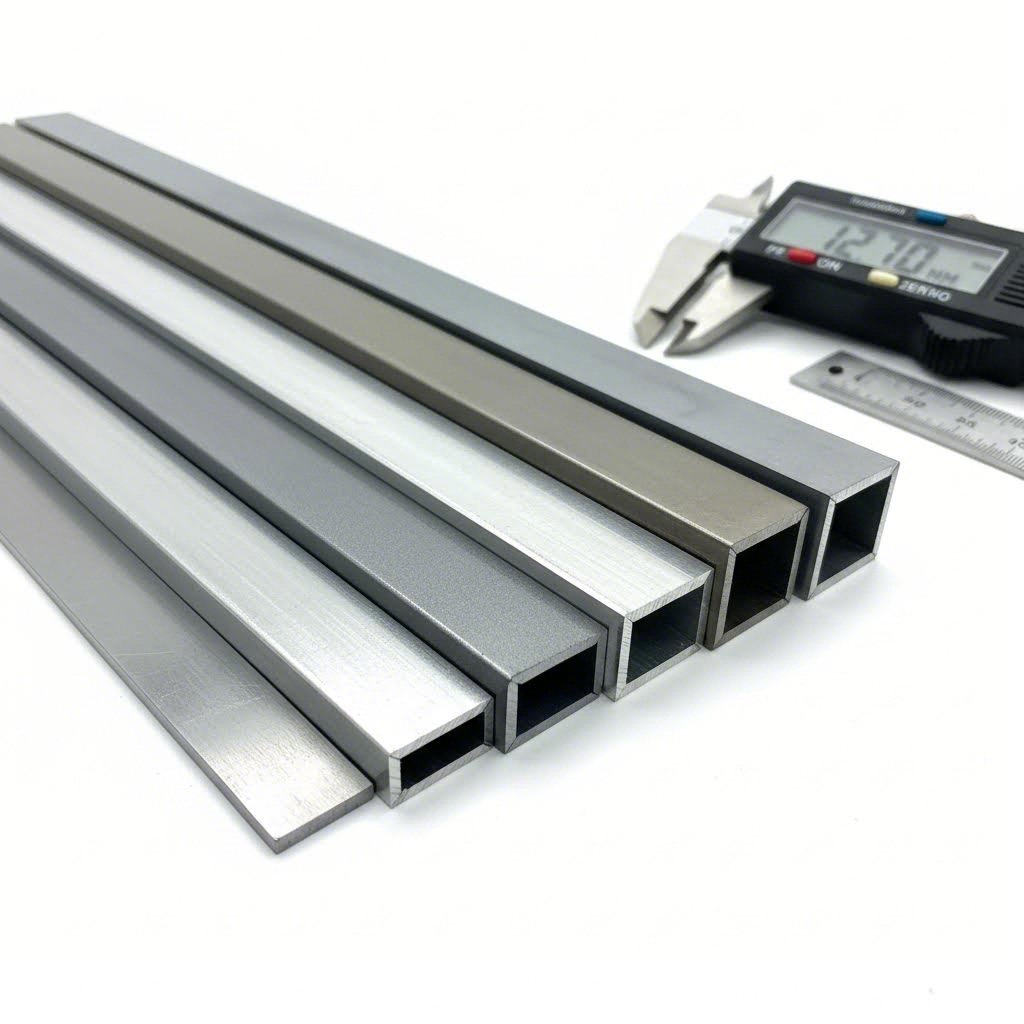
Sheet metal is any piece of metal with a thickness ranging between 0.5mm and 6mm (approximately 0.02" to 0.25"). This specific thickness range distinguishes it from foil metal (below 0.5mm) and plate metal (above 6mm), making it the backbone of modern industrial fabrication.
Defining Industrial Sheet Metal by Thickness Parameters
Picture a single sheet of metal arriving at your production floor. Its classification depends entirely on one critical measurement: thickness. According to industry standards, any metal falling within the 0.5mm to 6mm range earns the "sheet metal" designation. This isn't arbitrary. These parameters directly influence formability, weight characteristics, and structural performance in industrial applications.
Why does this matter for your projects? Sheet metal thickness determines everything from how easily a material can be bent or stamped to how it performs under stress. A steel sheet measuring 3mm behaves dramatically differently than one at 0.8mm during press brake operations or deep drawing processes.
Why Gauge Measurements Matter in Manufacturing
Here's where many engineers encounter confusion. The gauge of metal doesn't follow intuitive logic. Lower gauge numbers actually indicate thicker material, while higher numbers mean thinner sheets. A 10-gauge steel sheet measures approximately 3.4mm, while 20-gauge comes in around 0.9mm.
What makes this even more complex? Different metals have different gauge-to-thickness relationships. According to Metal Supermarkets, an 8-gauge aluminum sheet measures 0.1285 inches, while an 8-gauge stainless steel sheet measures 0.17187 inches. The same gauge number, but completely different actual thicknesses. This distinction becomes critical when you're specifying materials for precision industrial applications.
Sheet Metal vs Plate Metal Classification
The dividing line between sheet and metal plate sits firmly at 6mm (approximately 1/4 inch). Cross that threshold, and you're working with plate metal, which belongs to the structural metal family. Drop below 0.5mm, and your material becomes foil.
This classification impacts more than just terminology. It affects:
- Processing methods: Sheet metal undergoes forming, stamping, and bending operations that plate metal cannot accommodate
- Equipment requirements: Different machinery handles each classification
- Cost structures: Material costs and processing expenses vary significantly between categories
- Application suitability: Automotive body panels require sheet metal flexibility, while heavy machinery frames demand plate thickness
Understanding these distinctions positions you to make informed decisions before your project ever reaches the production floor. Whether you're specifying materials for electronics enclosures or structural automotive components, the sheet metal industrial landscape rewards those who master these fundamentals first.
Understanding Metal Gauge Thickness for Industrial Applications
Now that you understand what qualifies as sheet metal, the next question becomes: how do you specify exactly how thick your material needs to be? This is where the metal gauge thickness system enters the picture, and honestly, it's one of the most counterintuitive measurement standards you'll encounter in manufacturing.
Here's what trips up even experienced engineers: a lower gauge number means thicker material. Sounds backwards? It is. According to SendCutSend, this peculiar system dates back to the 1800s, originating from wire manufacturing. The gauge number represented how many times a wire was drawn through reduction dies. More drawing operations meant thinner wire, hence higher gauge numbers for thinner material.
Standard Gauge to Millimeter Conversion Reference
When you're specifying materials for industrial sheet metal projects, having accurate conversion data prevents costly ordering mistakes. The table below covers the most commonly used gauges in manufacturing applications:
| Gauge | Steel Thickness (inches) | Steel Thickness (mm) | Aluminum Thickness (inches) | Aluminum Thickness (mm) |
|---|---|---|---|---|
| 7 | 0.1793 | 4.55 | 0.1443 | 3.67 |
| 11 | 0.1196 | 3.04 | 0.0907 | 2.30 |
| 12 | 0.1046 | 2.66 | 0.0808 | 2.05 |
| 14 | 0.0747 | 1.90 | 0.0641 | 1.63 |
| 16 | 0.0598 | 1.52 | 0.0508 | 1.29 |
| 18 | 0.0478 | 1.21 | 0.0403 | 1.02 |
| 20 | 0.0359 | 0.91 | 0.0320 | 0.81 |
| 22 | 0.0299 | 0.76 | 0.0253 | 0.64 |
Notice something critical? The 7 gauge thickness for steel measures 4.55mm, while the same 7 gauge in aluminum comes in at just 3.67mm. That's nearly a full millimeter difference from identical gauge numbers.
How Steel and Aluminum Gauges Differ
Why do different materials have completely different gauge-to-thickness relationships? It comes down to density. According to Xometry, gauge numbers were developed by measuring sheet metal thickness in relation to its weight per square foot. Since aluminum weighs significantly less than steel, the same gauge number produces different actual thicknesses.
Consider this practical example from industry data:
- 10 gauge stainless steel: 0.135 inches thick
- 10 gauge aluminum: 0.102 inches thick
That's a 0.033" difference, which falls well outside tolerance limits for most precision applications. Imagine ordering 11 gauge steel thickness for a structural component but accidentally referencing an aluminum chart. Your parts would arrive significantly thinner than expected, potentially compromising the entire project.
The takeaway? Always verify you're using the correct material-specific gauge chart. Better yet, specify thickness in actual measurements (millimeters or inches) to eliminate any ambiguity with your supplier.
Selecting the Right Gauge for Structural Applications
Matching gauge selection to your application requirements involves balancing three primary factors: load-bearing capacity, formability, and cost. Here's how to think through each decision:
Load-bearing capacity: Thicker gauges provide superior structural integrity. For heavy-duty applications like chassis components or load-bearing brackets, 11 gauge thickness or lower (thicker) typically delivers the necessary strength. As Central States notes, there can be a 40% difference in dent protection between the low and high end of even a single gauge range.
Formability considerations: Thinner materials bend and form more easily. If your part requires complex geometries or tight bend radii, 16 gauge steel thickness or higher (thinner) often produces better results with less springback. However, go too thin, and you sacrifice the structural performance your application demands.
Cost optimization: Material costs increase with thickness, but so does durability. The 22 gauge steel thickness works perfectly for lightweight enclosures and decorative applications where strength isn't critical. Meanwhile, heavy industrial equipment might justify the premium for 7 gauge steel thickness when long-term performance matters most.
Before finalizing your gauge selection, ask yourself: what's the minimum thickness that meets my structural requirements? Starting there and adding safety margin gives you the optimal balance between performance and material costs. With gauge fundamentals covered, the next critical decision involves selecting the right base material for your specific industrial application.
Industrial Sheet Metal Materials and Their Performance Characteristics
You've mastered gauge measurements. Now comes the decision that shapes everything from fabrication costs to final product longevity: which material do you actually specify? According to Prototek, choosing the right material is essential in sheet metal fabrication to ensure good performance, durability, and appearance. Let's break down your primary options.
Carbon Steel Properties for Heavy Industrial Use
Carbon steel remains the workhorse of steel sheet metal applications. Why? It delivers exceptional strength-to-cost ratios that few materials can match. The carbon content, ranging from 0.05% to over 2%, directly determines the material's hardness and wear resistance.
Here's what makes carbon steel ideal for demanding applications:
- Tensile strength: Higher carbon content increases hardness and load-bearing capacity, making it suitable for heavy machinery components
- Formability: Lower carbon steel sheets weld more easily and offer greater flexibility during bending operations
- Cost factors: Among the most economical steel metal sheets available, especially for high-volume production runs
- Corrosion resistance: Limited natural protection, typically requires coating or painting for outdoor applications
Carbon steel excels in structural beams, automotive frames, and industrial equipment where raw strength matters more than corrosion resistance. However, if your application involves moisture exposure, you'll need to consider protective treatments or alternative materials.
When Aluminum Outperforms Steel in Sheet Applications
Imagine you're designing aerospace components or automotive body panels where every gram matters. This is where aluminum panels become your strategic advantage. According to Heather & Little, aluminum is lightweight, corrosion-resistant, and has good thermal conductivity, making it suitable for applications requiring heat dissipation.
Aluminum alloys offer distinct advantages:
- Weight reduction: Approximately one-third the weight of steel sheets at comparable thicknesses
- Natural corrosion resistance: Forms a protective oxide layer without additional treatment
- Thermal conductivity: Excellent heat dissipation properties for electronics enclosures and heat exchangers
- Recyclability: Highly recyclable material that supports sustainability initiatives
Common aluminum alloys serve different purposes. The 6061 alloy delivers excellent weldability for structural applications, while 5052 alloy performs exceptionally in marine environments. When ordering 4 x 8 aluminium sheets for production, specifying the correct alloy matters as much as thickness selection.
One consideration: aluminum bars and sheets typically cost more per pound than carbon steel. However, the weight savings often offset material premiums in transportation and fuel efficiency calculations.
Galvanized and Coated Options for Corrosion Resistance
What happens when you need steel's strength but can't tolerate its vulnerability to rust? Galvanized steel bridges this gap perfectly. The zinc coating applied through galvanization creates a sacrificial barrier that protects the underlying steel for decades.
Consider galvanized steel when your project involves:
- Outdoor installations: Roofing, exterior cladding, and agricultural equipment
- Moisture exposure: HVAC ductwork, drainage systems, and marine-adjacent structures
- Extended service life requirements: Infrastructure components where replacement costs are prohibitive
Stainless steel takes corrosion resistance even further. With chromium content of at least 10.5%, it resists rust, stains, and chemical attack. Medical equipment, food processing machinery, and chemical processing facilities rely on stainless steel's durability under harsh conditions.
Here's the trade-off matrix for your material decision:
| Material | Strength | Corrosion Resistance | Weight | Relative Cost |
|---|---|---|---|---|
| Carbon Steel | High | Low | Heavy | $ |
| Stainless Steel | High | Excellent | Heavy | $$$ |
| Aluminum | Moderate | Good | Light | $$ |
| Galvanized Steel | High | Very Good | Heavy | $$ |
Your material choice cascades into every downstream decision. Carbon steel requires different cutting parameters than aluminum. Stainless steel demands specialized welding techniques. Galvanized coatings can release toxic fumes during welding without proper ventilation. Understanding these material-specific requirements before production begins prevents costly mid-project adjustments.
With your material selected, the next critical decision involves choosing the optimal cutting process for your specific combination of material type, thickness, and production volume.
Sheet Metal Cutting Processes for Industrial Production
You've selected your material and specified the right gauge. Now comes the decision that directly impacts part quality, production speed, and your bottom line: which cutting method should you use? According to Sintel Inc., the quality of a finished product is often determined by the very first step, the cut. Sheet metal cutting isn't just about separating material. It's about achieving the precision, edge quality, and efficiency your application demands.
The truth? There's no single best cutting method. Each process excels under specific conditions. Your job is matching the right technology to your material type, thickness requirements, and production volume. Let's examine how each process performs where it matters most.
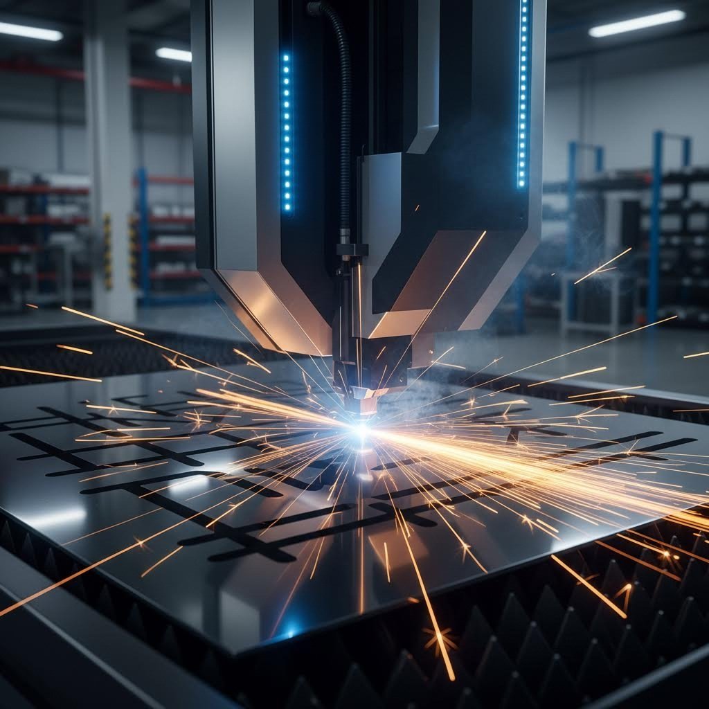
Laser Cutting Precision for Complex Industrial Parts
When your parts require intricate geometries and tight tolerances, laser cutting delivers unmatched precision. The process uses a highly focused beam of light, typically from a CO2 or fiber laser source, to melt, burn, or vaporize material along the programmed cut path. According to StarLab CNC, the highly concentrated energy creates extremely precise cuts with minimal heat-affected zones.
What makes laser cutting ideal for precision work?
- Tolerance capability: Achieves tolerances as tight as ±0.001" on thin materials
- Edge quality: Produces smooth, clean edges requiring minimal secondary finishing
- Speed on thin materials: Fiber lasers dominate cutting speeds on sheets under 1/4" thick
- Minimal HAZ: Localized heating reduces material distortion and warping
Here's the limitation: cutting speed decreases significantly as material thickness increases. According to industry data, laser systems experience dramatic slowdowns on materials over 1" thick. For perforated sheet metal applications with hundreds of small holes, laser cutting excels at creating consistent, burr-free openings. But for thick plate processing, you'll need to consider alternatives.
Plasma vs Waterjet for Thick Gauge Processing
When your project involves mid-range to thick materials, two technologies compete for dominance: plasma and waterjet cutting. Each brings distinct advantages depending on your priorities.
Plasma cutting uses an electric arc to heat compressed gas until it ionizes, forming plasma at temperatures up to 45,000°F. According to StarLab CNC, CNC plasma tables excel in cutting speed on materials from 0.018" to 2" thick. A high-powered system can cut 1/2" mild steel at speeds exceeding 100 inches per minute.
Plasma's advantages include:
- Speed: Significantly faster than waterjet for conductive metals
- Cost efficiency: Lower equipment and operating costs than laser or waterjet
- Thickness range: Handles material from 0.018" to 2" with optimal performance
Waterjet cutting takes a completely different approach. Using water pressurized up to 90,000 PSI mixed with abrasive particles, it erodes material without generating heat. This cold cutting process preserves material properties that heat-based methods can alter.
Waterjet excels when:
- Heat sensitivity matters: Zero thermal distortion for titanium, specialty aluminum alloys, and heat-treated materials
- Extreme thickness required: Cuts materials up to 12 inches thick
- Material versatility needed: Handles virtually any material including composites and non-metals
The trade-off? Waterjet operates at significantly slower speeds, typically 5-20 inches per minute. For high-volume perforated metal sheet production, this speed limitation can bottleneck your entire operation. For perforated aluminum sheet applications requiring heat-sensitive processing, waterjet's precision justifies the slower pace.
High-Volume Punching and Shearing Operations
Sounds complex? Thermal cutting processes get all the attention, but mechanical cutting methods, punching and shearing, often deliver superior economics for high-volume production. These processes physically remove material rather than melting it, creating different cost and quality dynamics.
Punching uses a die and punch set to create holes, cutouts, and formed features in flat sheet metal. Modern CNC turret punch presses can cycle at speeds exceeding 1,000 hits per minute. For perf metal applications requiring thousands of identical holes, punching achieves cycle times that thermal processes simply cannot match.
Shearing provides the most economical method for straight cuts on flat stock. While limited to linear cuts, shearing operations require minimal setup and deliver high throughput for blanking operations.
According to Hypertherm, productivity involves more than just cut speed. Consider programming time, job setup requirements, secondary operation needs, and material utilization. Punching eliminates many secondary operations required after thermal cutting, reducing total cost per completed part.
| Cutting Method | Thickness Range | Precision Tolerance | Relative Speed | Cost-Effectiveness |
|---|---|---|---|---|
| Laser | 0.001" - 1" | ±0.001" - ±0.005" | Very High (thin) | High initial, moderate operating |
| Plasma | 0.018" - 2" | ±0.015" - ±0.030" | Very High | Low initial, low operating |
| Waterjet | 0.001" - 12" | ±0.003" - ±0.010" | Low | Moderate initial, high operating |
| Punching | 0.020" - 0.25" | ±0.005" - ±0.010" | Very High | Low per part (high volume) |
| Shearing | 0.020" - 0.5" | ±0.010" - ±0.030" | Very High | Lowest (straight cuts only) |
Your cutting method decision cascades into every downstream process. According to Hypertherm, cut quality impacts weld preparation requirements, painting outcomes, and even threading viability. A weld-ready cut reduces secondary grinding operations, streamlining production and cutting labor costs.
The key questions to ask before selecting your cutting process:
- What's my typical material type and thickness range?
- How critical are edge quality and dimensional tolerances?
- What production volumes will I maintain over time?
- Do I need heat-free processing to preserve material properties?
With your cutting strategy defined, the next step involves understanding how forming and shaping techniques transform flat sheets into functional three-dimensional components.
Sheet Metal Forming Techniques for Industrial Scale Production
Your flat sheet metal has been cut to specification. Now what? Transforming that two-dimensional blank into a functional three-dimensional component requires mastering sheet metal forming, the processes that bend, stretch, and shape material without removing any of it. According to Klassen Custom Fabricating, metal forming works because of metal plasticity, the ability of metals to deform permanently without breaking. When force exceeds the metal's yield strength, the metal flows into new shapes.
Here's the critical insight: every forming method carries inherent limitations that directly impact your design options. Understanding these constraints before finalizing part geometry prevents costly redesigns during production. Let's examine the primary sheet metal manufacturing processes and when each delivers optimal results.
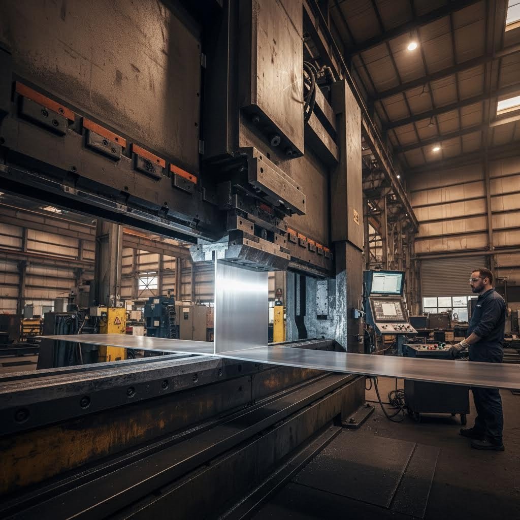
Press Brake Operations for Precision Bending
When your parts require angled bends with tight tolerances, press brake forming delivers the control you need. According to ADHMT, press braking completes metal forming by bending the metal sheet with upper and lower dies. The process drives the upper tool (punch) into the lower tool (die) to create precise angles.
Press brake operations use three primary bending techniques:
- Air bending: The punch doesn't force the sheet to the die bottom, leaving space beneath. This technique requires less tonnage and allows multiple angles from a single die set
- Bottom bending: The punch forces material firmly against the die surface, providing tighter angle control with reduced springback
- Coining: Applies maximum pressure to permanently set the bend angle, virtually eliminating springback
What makes press braking ideal for certain applications? According to CustomPartNet, the efficiency of press braking process is very high, but generally it can only deal with small and short workpieces. For 14 gauge sheet metal and similar thicknesses, press brakes deliver excellent repeatability on parts ranging from small brackets to enclosures up to 20 feet long.
The limitation? Press brakes cannot bend material beyond their body length. Complex parts requiring multiple bends demand careful sequencing to avoid tool interference with previously formed sections.
Roll Forming for High-Volume Production Runs
Imagine needing thousands of identical profiles, like structural channels, roofing panels, or automotive trim. Roll forming excels precisely here. According to ADHMT, roll forming progressively bends flat sheet metal into the desired shape through a series of roller stations.
Unlike press braking's single-stroke approach, roll forming gradually shapes material through sequential forming stations. Each set of rollers incrementally bends the metal until the final profile emerges. This progressive method produces several distinct advantages:
- Unlimited part length: Material feeds continuously from coils, eliminating length restrictions
- Consistent quality: Produces strict tolerances on complex profiles with highly uniform surfaces
- High-strength results: Material strengthening occurs during the cold forming process
- Secondary integration: Welding, punching, and laser cutting can integrate into the production line
Roll forming handles 12 gauge sheet metal and thicker materials without breaking, making it suitable for structural applications. However, the technology requires significant tooling investment, making small-batch production cost-prohibitive. Reserve roll forming for high-volume runs where tooling costs amortize across thousands of parts.
Stamping Techniques for Automotive and Structural Components
When production volumes justify dedicated tooling and cycle time matters most, stamping delivers unmatched throughput. According to Klassen Custom Fabricating, stamping uses dies to cut and form sheet metal in a single operation. A press forces the metal into the die, creating the desired shape at speeds that thermal forming processes cannot approach.
The automotive industry relies heavily on stamping for body panels, brackets, and structural components. Electronics manufacturers use stamping for connectors, terminals, and heat sinks. What makes this process essential for these applications?
- Speed: High-speed presses cycle rapidly, producing hundreds of parts per hour
- Repeatability: Die-formed parts maintain consistent dimensions across production runs
- Complexity: Progressive dies perform multiple operations in a single press stroke
The trade-off involves tooling costs. Custom stamping dies represent significant investment, and design changes require expensive modifications. For 14 gauge steel sheet applications requiring high volumes, the per-part economics become favorable once production quantities justify the initial tooling expense.
The Forming Process Workflow
Regardless of which forming method you select, successful sheet metal manufacturing follows a consistent workflow:
- Design validation: Engineers verify that part geometry respects forming limitations including minimum bend radii, interference clearances, and material stretch requirements
- Material preparation: Flat sheet metal is cut to appropriate blank dimensions, with consideration for material stretch during forming
- Tooling setup: Dies, punches, or roller stations are installed and aligned according to part specifications
- Trial forming: Initial parts are produced and measured to verify dimensional accuracy
- Parameter adjustment: Settings are refined to compensate for springback and achieve target dimensions
- Production forming: Full-rate production begins with ongoing quality monitoring
- Secondary operations: Formed parts may require deburring, welding, or finishing before completion
Matching Forming Methods to Application Requirements
How do you select the right forming process? Four factors drive the decision:
Part geometry: Simple bends suit press braking. Uniform profiles favor roll forming. Complex shapes with multiple features point toward stamping or hydroforming. According to Klassen Custom Fabricating, drawing pulls sheet metal into a die cavity to form cup-shaped parts, while hydroforming uses fluid pressure to create complex shapes from tubes or sheets.
Production volume: Low volumes justify flexible processes like press braking where setup costs remain minimal. According to ADHMT, press braking is suitable for small workpiece manufacturing in small batches. High volumes demand stamping or roll forming where tooling investments amortize across thousands of parts.
Material properties: Thinner materials like 20 gauge sheet metal form more easily with less springback. Thicker materials and high-strength alloys require greater forming forces and may limit achievable geometries. According to CustomPartNet, the amount of springback depends upon several factors including the material, bending operation, and the initial bend angle and bend radius.
Tolerance requirements: Precision applications demand forming methods that minimize springback variation. Roll forming produces strict tolerances for complex profiles. Press braking with coining reduces springback on critical dimensions. Stamping delivers the most consistent results when tooling is properly designed.
Understanding these forming fundamentals positions you to communicate effectively with manufacturers and make informed decisions about part design. The next critical step involves selecting the right joining methods to assemble your formed components into functional assemblies.
Joining and Assembly Methods in Sheet Metal Manufacturing
Your components are cut and formed. Now comes the decision that determines whether your finished product holds together under real-world conditions: how do you join those individual pieces into a functional assembly? According to EZG Manufacturing, the method of assembly plays a critical role in durability, cost, and lead time. Whether you're building a rugged stainless steel box for industrial equipment or assembling compact electronics enclosures, your joining method directly impacts long-term performance.
Here's what makes sheet metal joining applications particularly challenging: you're working with relatively thin materials that can warp under heat, distort under stress, or fatigue at connection points. The right joining method prevents these failures while matching your production requirements.
Welding Methods for Sheet Metal Assembly
When permanent, high-strength connections matter most, welding remains the go-to solution for sheet metal work. According to TWI Global, fusion welding processes involve melting and resolidification of the material in the zone where the join is required, creating bonds often stronger than the base metal itself.
Two welding methods dominate industrial sheet metal working:
- MIG welding: Delivers faster travel speeds and works well on thicker materials; ideal for high-volume production where speed matters
- TIG welding: Provides superior control and cleaner welds on thin materials; preferred for visible joints and precision applications
What are the advantages of welding?
- Creates permanent, high-strength joints that withstand significant loads
- Produces seamless connections with no added hardware weight
- Enables watertight and airtight seals when properly executed
What are the limitations?
- Heat input can distort thin sheet metal gauges
- Requires skilled operators and specialized tools for sheet metal fabrication
- Galvanized and coated materials release toxic fumes without proper ventilation
Mechanical Fastening vs Permanent Joining Solutions
What happens when you need to disassemble components for maintenance, inspection, or repair? Mechanical fastening provides the versatility welding cannot. According to TWI Global, mechanical joining uses clamps, screws, bolts, or rivets to connect parts, allowing disassembly when needed.
Riveting creates permanent mechanical connections by deforming a metal pin through pre-drilled holes. It's commonly used in aerospace and structural applications where welding heat would compromise material properties.
Bolted connections offer the ultimate serviceability. Need to replace a worn component? Simply remove the fasteners and swap parts. This approach reduces long-term maintenance costs on equipment requiring periodic service.
Advantages of mechanical fastening:
- Joins dissimilar materials that cannot be welded together
- Allows disassembly without destroying components
- Requires less specialized equipment than welding operations
- Eliminates heat distortion concerns entirely
Disadvantages to consider:
- Holes drilled for fasteners can become stress concentration points
- Screws and bolts may loosen under vibration over time
- Added hardware increases assembly weight and part count
Adhesive bonding offers a third path when neither welding nor mechanical fastening suits your application. According to EZG Manufacturing, adhesives distribute stress more evenly across bonded areas, making them well-suited for lightweight or vibration-prone designs. This method works particularly well for joining dissimilar materials or when visible fasteners would compromise aesthetics.
Quality Considerations in Sheet Metal Joining
Selecting the right joining method only matters if execution meets quality standards. According to TWI Global, even when the most suitable joining method has been chosen, factors like process failures and human error can affect joint integrity.
Common quality issues by joining type:
- Welding defects: Porosity, incomplete fusion, and heat-affected zone cracking require visual and non-destructive testing inspection
- Mechanical fastener failures: Improper torque, hole misalignment, and fastener loosening demand ongoing monitoring
- Adhesive bond failures: Surface contamination, inadequate cure time, and environmental exposure can compromise joint strength
Preventing these defects requires proper inspection protocols. Visual inspection catches surface-level issues. Destructive testing on sample parts verifies joint strength. Non-destructive methods like ultrasonic testing reveal internal flaws without damaging production parts.
The joining method you select affects more than just assembly. It determines product durability, serviceability options, and total manufacturing efficiency throughout your product's lifecycle.
Your joining decision cascades into every downstream consideration. Welded assemblies offer maximum strength but limit field serviceability. Mechanical fastening enables maintenance access but adds weight and potential failure points. Understanding these trade-offs positions you to specify the optimal approach for your specific industrial requirements. With joining methods understood, the next step involves examining how different industries apply these principles to meet sector-specific standards.
Industry-Specific Sheet Metal Applications and Requirements
You've mastered materials, cutting, forming, and joining. But here's what separates successful projects from costly failures: understanding that every industry applies these fundamentals differently. A tolerance acceptable for HVAC ductwork would fail catastrophically in aerospace applications. A material perfect for automotive chassis would corrode within months in marine environments. According to industry standards, sheet metal parts play a crucial role across sectors, but strict standards and regulations ensure safety and performance vary dramatically by application.
Let's examine how major industries translate general sheet metal gauge thickness knowledge into sector-specific requirements that drive real-world manufacturing decisions.
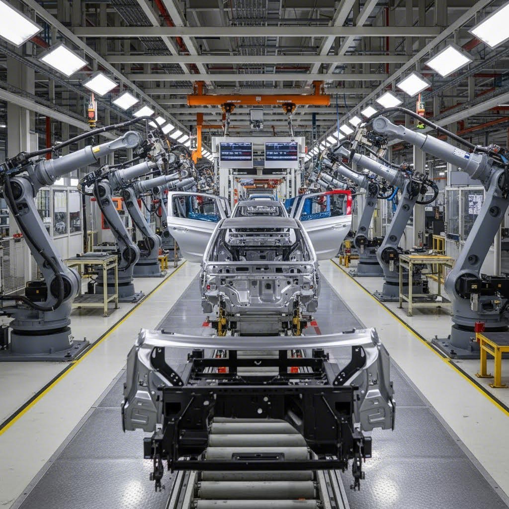
Automotive Chassis and Structural Component Requirements
When you're manufacturing chassis components, body panels, or structural brackets for vehicles, three priorities dominate: weight reduction, crash performance, and production economics. Every kilogram matters for fuel efficiency, yet structural integrity cannot be compromised.
Automotive sheet metal applications typically specify:
- Materials: High-strength low-alloy (HSLA) steel, advanced high-strength steel (AHSS), and aluminum alloys for weight-critical components
- Typical gauges: 18-22 gauge for body panels; 12-16 gauge for structural reinforcements
- Tolerances: ±0.5mm dimensional accuracy for stamped components; tighter for safety-critical parts
- Certification: IATF 16949 quality management system certification is essential for tier-one and tier-two suppliers
What makes automotive unique? Volume drives everything. Production runs of hundreds of thousands of identical parts justify extensive tooling investments that would bankrupt low-volume operations. Stamping processes dominate, with progressive dies producing complex components in single press strokes.
Aerospace Standards and Precision Tolerances
Imagine the consequences of a structural failure at 35,000 feet. Aerospace sheet metal applications operate under the most stringent standards in manufacturing. According to aerospace industry guidelines, material selection must meet stringent standards ensuring structural integrity, durability, and performance in demanding environments.
Aerospace requirements differ fundamentally from other sectors:
- Materials: Aluminum alloys (2024, 7075), titanium, and specialty stainless steels chosen for strength-to-weight ratios and fatigue resistance
- Tolerances: Often ±0.05mm or tighter; some critical components require ±0.025mm
- Certification: AS9100 quality management system; NADCAP accreditation for special processes
- Traceability: Complete material certification and process documentation from raw material to finished part
According to aerospace manufacturing standards, quality control measures include dimensional inspection, material testing, and non-destructive testing (NDT) to guarantee parts are free from defects and conform to design specifications. Every sheet metal component carries documentation proving its lineage and quality status.
HVAC Ductwork and Enclosure Specifications
HVAC applications prioritize different factors entirely. Corrosion resistance, noise reduction, and installation flexibility matter more than achieving aerospace-level precision. Decorative metal panels and functional components must balance performance with cost-effective production.
Typical HVAC sheet metal specifications include:
- Materials: Galvanized steel dominates; aluminum for corrosive environments; stainless steel for commercial kitchens
- Typical gauges: 22-26 gauge for residential ductwork; 18-22 gauge for commercial applications
- Tolerances: ±1.5mm acceptable for most ductwork; tighter for custom enclosures
- Certification: ISO 9001 quality management; SMACNA standards for duct construction
Roll forming dominates HVAC production, creating continuous profiles for duct sections. The relatively relaxed tolerances allow high-speed production that keeps costs aligned with construction budgets.
Construction and Architectural Applications
Building facades, aluminum metal roofing, and structural components require durability measured in decades rather than years. Weather exposure, thermal cycling, and aesthetic requirements drive material and finish selections that differ substantially from enclosed industrial applications.
Construction sheet metal considerations include:
- Materials: Galvanized steel, Galvalume, aluminum, copper, and zinc for exterior applications
- Typical gauges: 24-29 gauge for standing seam roofing; heavier gauges for structural panels
- Corrosion protection: Paint systems rated for 20+ years; metallic coatings for extreme environments
- Aesthetic options: Decorative metal sheets and decorative metal fence panels require consistent finish quality across large surface areas
Black metal roofing and other architectural finishes demand color consistency that manufacturing processes must maintain across production lots. Perforated metal panels provide functional benefits like acoustic control and sunshading while contributing to building aesthetics.
Electronics Enclosure Requirements
Electronics enclosures protect sensitive components from environmental factors while managing electromagnetic interference (EMI). These applications combine precision requirements with specific material properties that general fabrication rarely encounters.
Electronics enclosure specifications typically require:
- Materials: Cold-rolled steel for EMI shielding; aluminum for lightweight portable devices; stainless steel for medical equipment
- Typical gauges: 18-22 gauge for rack-mount enclosures; lighter gauges for portable housings
- Tolerances: ±0.25mm for panel alignment; tighter for mating surfaces
- Special requirements: EMI/RFI shielding effectiveness; IP-rated sealing for harsh environments
Industry Requirements Comparison
| Industry | Primary Materials | Typical Gauge Range | Tolerance Standard | Key Certification |
|---|---|---|---|---|
| Automotive | HSLA Steel, Aluminum | 12-22 gauge | ±0.5mm | IATF 16949 |
| Aerospace | Aluminum, Titanium | Application-specific | ±0.05mm or tighter | AS9100, NADCAP |
| HVAC | Galvanized Steel | 18-26 gauge | ±1.5mm | ISO 9001 |
| Construction | Galvanized, Aluminum | 24-29 gauge | ±1.0mm | ISO 9001 |
| Electronics | CRS, Aluminum, Stainless | 18-22 gauge | ±0.25mm | ISO 9001, UL |
Certification Standards Explained
Why do these certifications matter for your sourcing decisions? Each standard addresses specific quality management requirements:
ISO 9001: The baseline quality management system applicable across industries. Ensures consistent processes and continuous improvement.
IATF 16949: Automotive-specific quality standard building on ISO 9001 with additional requirements for defect prevention, variation reduction, and supply chain management. According to industry requirements, automotive manufacturers require this certification from their suppliers.
AS9100: Aerospace quality management standard incorporating ISO 9001 requirements plus aerospace-specific additions for safety, reliability, and product conformity. Mandatory for suppliers in the aerospace supply chain.
NADCAP: Special process accreditation for aerospace covering welding, heat treating, non-destructive testing, and other critical processes. According to aerospace standards, compliance involves rigorous inspection, testing, and documentation to verify integrity and performance.
Understanding industry-specific requirements before engaging suppliers prevents costly mismatches between your expectations and their capabilities.
Your industry dictates which certifications matter, what tolerances are achievable, and which materials provide optimal performance. A supplier excelling in HVAC ductwork may lack the precision capabilities aerospace applications demand. Conversely, aerospace-certified suppliers may price themselves out of cost-sensitive construction projects. Matching supplier capabilities to your specific industry requirements becomes the next critical decision in your sheet metal industrial journey.
Selecting the Right Sheet Metal Manufacturing Partner
You understand materials, processes, and industry requirements. Now comes the decision that ties everything together: which supplier actually delivers on their promises? According to Custom Metal Pro, choosing the right sheet metal fabrication supplier plays a critical role in product quality, cost control, and delivery reliability. The sheet metal manufacturing industry is filled with capable fabricators, but finding the right partner for your specific requirements demands systematic evaluation.
Here's the challenge: a supplier's website might list impressive capabilities, but how do you verify they can actually execute at the quality and volume your project demands? Let's walk through the evaluation criteria that separate exceptional industrial sheet metal fabrication partners from those who merely look good on paper.
Evaluating Manufacturer Capabilities and Certifications
Start with equipment. According to industry guidance, a supplier's equipment and process range directly affect part accuracy and repeatability. Limited capabilities often lead to outsourcing, longer lead times, and quality variation. In-house fabrication capabilities ensure better control over quality, cost, and delivery.
What should you look for when reviewing a sheet metal gauge table of capabilities?
- Cutting equipment: Laser, plasma, waterjet, and punching capabilities matching your material and thickness requirements
- Forming capacity: Press brake tonnage and bed length; roll forming for high-volume profiles; stamping presses for production runs
- Joining capabilities: Welding certifications, mechanical assembly, and hardware insertion equipment
- Finishing options: Powder coating, painting, plating, and surface treatment capabilities
- Secondary operations: CNC machining, threading, and assembly services that reduce your supply chain complexity
Certifications validate that a supplier maintains consistent quality systems. For the sheet metal fabrication industry, key certifications include:
- ISO 9001: Baseline quality management applicable across industries
- IATF 16949: Automotive-specific requirements for defect prevention and supply chain management
- AS9100: Aerospace quality standards with enhanced traceability and documentation
When evaluating automotive applications, IATF 16949 certification becomes non-negotiable. Suppliers like Shaoyi (Ningbo) Metal Technology demonstrate this commitment through their certified quality systems for chassis, suspension, and structural components.
Prototyping Speed and Production Scalability Factors
How quickly can a supplier validate your design before committing to production tooling? According to All Metals Fab, moving a sheet metal part from prototype to production is where ideas meet reality, and where many programs stumble.
Rapid prototyping capabilities reveal a supplier's engineering depth. A metal thickness gauge alone won't tell you whether your design is manufacturable. You need partners who can produce physical samples quickly, validate your assumptions, and identify potential issues before they become expensive production problems.
Evaluate prototyping capabilities by asking:
- What is your typical turnaround time for first article samples?
- Can you produce prototypes using production-intent materials and processes?
- How do you handle design iterations during the prototyping phase?
- What inspection data accompanies prototype deliveries?
Leading suppliers in the sheet metal industry now offer rapid prototyping timelines measured in days rather than weeks. For example, Shaoyi delivers 5-day rapid prototyping with 12-hour quote turnaround, enabling faster design validation cycles that compress overall development timelines.
Production scalability matters equally. According to sourcing experts, production flexibility reduces supplier risk and supports long-term cooperation. Your ideal partner handles both prototype and low-volume sheet metal parts alongside medium and high-volume production without sacrificing quality or delivery performance.
Quality Assurance and Documentation Requirements
Quality isn't just about final inspection. According to industry standards, a reliable supplier must apply strict quality checks throughout fabrication and assembly, including incoming material inspection, in-process dimensional checks, final inspection before shipment, and documented quality records with traceability.
Your sheet metal thickness chart specifications mean nothing if the supplier cannot verify conformance. Ask potential partners about their quality infrastructure:
- Inspection equipment: CMM capabilities, optical comparators, surface finish measurement, and material verification tools
- Documentation practices: First article inspection reports, material certifications, dimensional inspection data, and process control records
- Traceability systems: Lot tracking from raw material through finished product
- Defect prevention: Statistical process control, error-proofing fixtures, and continuous improvement programs
The Critical Role of DFM Support
According to CoLab Software, for most companies, DFM is an afterthought. Engineers throw the design over the stage gate wall to their suppliers. Then, they find out too late that a part isn't toolable or the tolerances are too tight on a critical component.
Design for Manufacturability support transforms the supplier relationship from transactional to collaborative. According to fabrication experts, strong engineering support helps reduce cost, improve strength, and shorten production cycles through design for manufacturability review, material thickness and bend radius optimization, tolerance evaluation, and assembly improvement suggestions.
Effective DFM collaboration requires suppliers who provide:
- Access to engineering expertise during the design phase
- Clear feedback on manufacturability constraints before tooling commitment
- Recommendations for cost reduction without compromising function
- Rapid validation of design changes through prototype iteration
According to production scaling guidance, adopting a "prototype with production intent" mindset reduces revision churn later. Build prototypes using the material, thickness, and tooling assumptions that you expect in production.
Shaoyi exemplifies comprehensive DFM support in the automotive sector, providing engineering collaboration that optimizes designs for their automated mass production capabilities while maintaining IATF 16949-certified quality standards.
The best supplier relationships develop when engineering teams engage early, share design intent openly, and collaborate on manufacturability improvements before production commitments are made.
Your sheet metal gauge specifications, material selections, and tolerance requirements only translate into successful products when your manufacturing partner possesses both the capabilities and the collaborative mindset to execute reliably. With supplier evaluation criteria established, the final step involves synthesizing these decisions into a coherent project strategy.
Making Informed Decisions for Industrial Sheet Metal Projects
You've navigated materials, gauges, cutting methods, forming techniques, joining processes, industry requirements, and supplier evaluation criteria. Now comes the moment that determines whether all that knowledge translates into successful outcomes. According to TMCO, while pricing is always a key factor, the most cost-effective fabrication partner isn't necessarily the one with the lowest quote. It's the one who delivers value through accuracy, reliability, and long-term partnership.
Every decision you've made throughout this process connects to the next. Your metal sheet selection affects cutting method options. Your cutting choice influences forming capabilities. Your forming requirements drive joining decisions. And your industry standards determine which suppliers can actually serve your needs. Let's synthesize these factors into actionable guidance for your next project.
Balancing Cost, Quality, and Lead Time
Here's the reality every industrial buyer faces: you can optimize for any two of these factors, but rarely all three simultaneously. According to precision fabrication experts, understanding the variables that influence costs empowers you to make informed decisions from design optimization to material selection and scheduling.
Consider how each decision shifts the balance:
- Material selection: Standard 4x8 sheet metal in common alloys costs less and ships faster than specialty materials requiring custom mill runs
- Tolerance specifications: Tighter tolerances demand slower processing speeds, more frequent inspections, and higher rejection rates
- Production volume: High volumes spread setup costs across more parts, reducing per-unit pricing but extending initial lead times
- Finishing requirements: Each additional surface treatment adds cost and calendar time to your project
The fabricated metal products industry rewards buyers who understand these trade-offs and communicate priorities clearly. Need parts in two weeks? Expect premium pricing. Require aerospace-level tolerances on 18 gauge material? Budget for additional inspection time. Want the lowest possible unit cost? Plan for larger volume commitments.
The most successful sheet metal projects begin with honest conversations about priorities. When buyers and suppliers align on what matters most, everything else becomes negotiable.
From Design to Production Readiness
According to early supplier involvement research, engineering teams often drive innovation by conceptualizing new products, but translating these concepts into market-ready products requires a robust sourcing strategy. The gap between design intent and manufacturing reality causes more project failures than material defects or equipment problems.
What separates production-ready designs from problematic ones? Manufacturability awareness. According to Approved Sheet Metal, the most common issues involve part designs that don't adhere to guidelines for bend minimums and flange lengths. These calculations are critical in precision metal fabrication.
Before releasing designs for production, verify these elements:
- Bend radii compatibility: Ensure minimum bend radii match your specified material type and gauge
- Flange length adequacy: Confirm flanges meet minimum requirements for your forming equipment
- Tolerance achievability: Validate that specified tolerances are realistic for sheet metal processes versus machining
- Material availability: Confirm your specified metal sheets are readily available in required sizes
- Process compatibility: Ensure your design works with intended cutting, forming, and joining methods
According to collaboration research, by involving sourcing teams early in the development process, organizations can ensure that engineering designs are not only innovative but also manufacturable. This concurrent engineering approach ensures that long lead-time components are ordered early, reducing delays during production ramp-up.
Building Long-Term Manufacturing Partnerships
The sheet metal industry increasingly rewards partnership over transactional relationships. According to industry research, suppliers are often a valuable source of innovation, possessing specialized knowledge and expertise that can enhance product design and performance. Engaging suppliers early promotes stronger relationships, smoother project execution, reduced lead times, and improved supply chain resilience.
What defines a true manufacturing partner versus a commodity vendor?
- Engineering collaboration: Partners review designs for manufacturability and suggest improvements before quoting
- Transparent communication: Partners proactively communicate potential issues rather than delivering surprises at shipment
- Capacity commitment: Partners reserve capacity for your production needs rather than treating you as fill-in work
- Continuous improvement: Partners invest in process improvements that benefit your products over time
According to fabrication best practices, in precision metal fabrication, there is no such thing as too much information. The more details you provide about your part and its application, the better equipped your manufacturing partner will be to quickly and cost-effectively fabricate it.
Early collaboration between sourcing and engineering is no longer a luxury but a strategic imperative that can transform product development and drive competitive advantage.
For automotive applications where speed and quality intersect, Shaoyi (Ningbo) Metal Technology demonstrates what effective partnership looks like in practice. Their 5-day rapid prototyping capability compresses design validation cycles, while IATF 16949 certification ensures automotive-grade quality for chassis, suspension, and structural components. The 12-hour quote turnaround and comprehensive DFM support enable the kind of early collaboration that prevents costly late-stage redesigns.
Whether you're sourcing stamped brackets, formed enclosures, or complex welded assemblies, the principles remain consistent: specify materials accurately, understand process limitations, communicate tolerances clearly, and engage suppliers as partners rather than vendors. The nine decisions outlined throughout this guide provide the framework. Your next step is putting that framework into action.
Ready to accelerate your automotive sheet metal projects? Explore Shaoyi's rapid prototyping and precision stamping capabilities to see how the right manufacturing partner transforms your designs into production-ready components.
Frequently Asked Questions About Industrial Sheet Metal
1. What is industrial sheet metal?
Industrial sheet metal refers to any metal formed into flat pieces with thickness ranging between 0.5mm and 6mm (approximately 0.02" to 0.25"). This classification distinguishes it from foil metal (below 0.5mm) and plate metal (above 6mm). Common materials include cold rolled steel, mild steel, stainless steel, aluminum, brass, copper, nickel, and titanium. The specific thickness range makes sheet metal ideal for forming, stamping, and bending operations essential to manufacturing automotive components, HVAC systems, electronics enclosures, and structural applications.
2. How much does a sheet of sheet metal cost?
Sheet metal pricing varies significantly based on material type, gauge thickness, and sheet dimensions. Standard 4x8 sheet metal typically ranges from $25 to over $100 depending on specifications. Carbon steel offers the most economical option, while stainless steel and specialty alloys command premium pricing. Factors affecting cost include material grade, surface finish requirements, and order volume. High-volume purchases generally reduce per-sheet costs, while specialty materials or custom sizes increase pricing.
3. How do steel and aluminum gauges differ in thickness?
The same gauge number produces different actual thicknesses for steel and aluminum due to density differences. For example, 10-gauge stainless steel measures 0.135 inches while 10-gauge aluminum measures only 0.102 inches. This 0.033" difference occurs because gauge systems originated from weight-per-square-foot measurements. When specifying materials, always use material-specific gauge charts or specify thickness in actual measurements (millimeters or inches) to prevent ordering errors that could compromise project requirements.
4. What cutting method is best for industrial sheet metal?
The optimal cutting method depends on material type, thickness, precision requirements, and production volume. Laser cutting delivers precision tolerances as tight as ±0.001" for thin materials with complex geometries. Plasma cutting offers superior speed on materials 0.018" to 2" thick at lower operating costs. Waterjet cutting provides heat-free processing for sensitive materials up to 12" thick. Punching achieves highest throughput for high-volume perforated patterns. Evaluate your specific combination of material, thickness, and quantity to select the most cost-effective process.
5. What certifications should sheet metal suppliers have?
Required certifications depend on your industry. ISO 9001 provides baseline quality management across all sectors. Automotive applications require IATF 16949 certification for defect prevention and supply chain management. Aerospace projects demand AS9100 certification with NADCAP accreditation for special processes. Additionally, evaluate supplier capabilities including equipment range, prototyping speed, DFM support, and documentation practices. Partners like Shaoyi demonstrate commitment through IATF 16949 certification combined with 5-day rapid prototyping and comprehensive engineering support.