 Small batches, high standards. Our rapid prototyping service makes validation faster and easier —

Stamping Automotive Crossmembers: Engineering & Process Guide
TL;DR
Stamping automotive crossmembers is a specialized manufacturing process that transforms heavy-gauge steel into critical structural chassis components, such as K-frames and transmission supports. As OEMs prioritize lightweighting, the industry has shifted toward Advanced High-Strength Steel (AHSS), which introduces significant engineering challenges regarding springback and formability. Successful production requires precise die engineering—specifically techniques like over-bending to compensate for heat distortion—and high-performance lubrication systems to ensure dimensional accuracy during subsequent welding and assembly.
Functional Design and Engineering Context
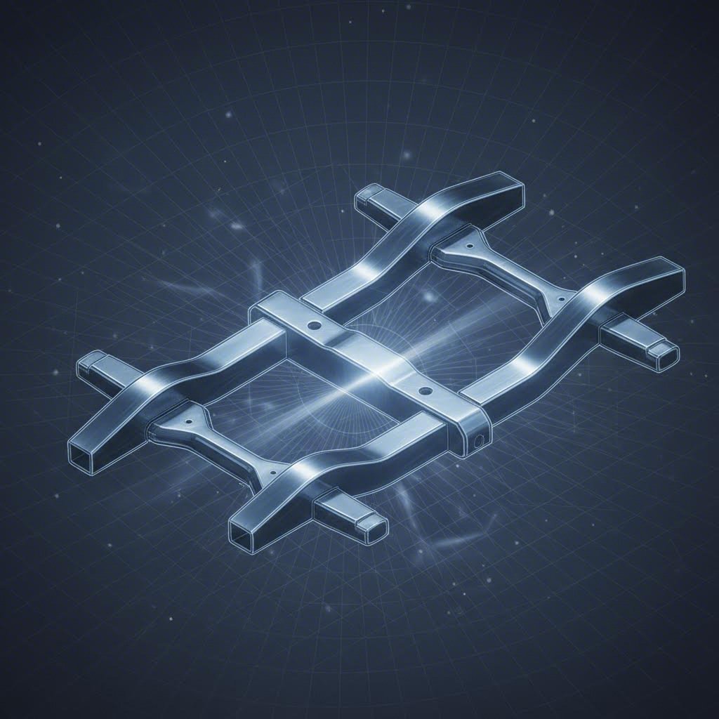
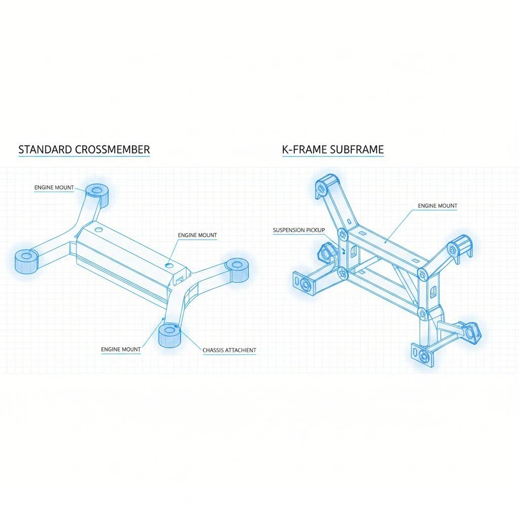
The automotive crossmember serves as a fundamental backbone of a vehicle's chassis, providing essential torsional rigidity and support for the suspension, engine, and transmission. Unlike cosmetic body panels, these components must withstand substantial dynamic loads and fatigue stress. In modern unibody constructions, the front crossmember (often referred to as a K-frame or subframe) integrates mounting points for the engine and lower control arms, demanding exceptional dimensional stability.
Engineering these components involves balancing structural integrity with packaging constraints. For example, a transmission crossmember must support the powertrain's weight while allowing clearance for exhaust routing and driveshafts. According to KIRCHHOFF Automotive, advanced designs often incorporate features like coupling jaws that require precise forming tolerances to ensure seamless integration with the main vehicle frame. The transition from simple stamped rails to complex, multi-point mounting structures has elevated the importance of precision metal stamping in maintaining vehicle safety and performance.
The structural role dictates the manufacturing method. While lighter components might use roll forming, the complex geometries and deep draw requirements of crossmembers typically necessitate heavy-gauge stamping. This process allows for the creation of reinforcing ribs and flanges directly into the part, optimizing the strength-to-weight ratio without adding external stiffeners.
Material Selection: The Shift to AHSS and UHSS
To meet stringent fuel economy standards and crash safety regulations, automotive engineers are increasingly specifying High-Strength Low-Alloy (HSLA) and Advanced High-Strength Steels (AHSS) over traditional mild steel. Materials such as SP251-540P HRPO (Hot Rolled Pickled and Oiled) are becoming standard for these applications because they offer superior tensile strength at thinner gauges.
However, the adoption of these stronger materials complicates the stamping process. As material strength increases, so does the phenomenon of springback—the tendency of the metal to return to its original shape after forming. A case study involving a 3.1mm thick automotive OEM crossmember highlights the necessity of specialized process controls when working with these grades. The high yield strength requires significantly greater press tonnage and more robust die materials to prevent premature tool wear.
Selecting the right material is a trade-off between formability and performance. Ultra-High-Strength Steels (UHSS) may reduce vehicle weight, but they often have lower elongation limits, making them prone to cracking during deep draw operations. Engineers must collaborate early with stamping partners to verify that the chosen material grade can achieve the necessary geometry without compromising the part's structural integrity.
Advanced Stamping Processes and Die Engineering
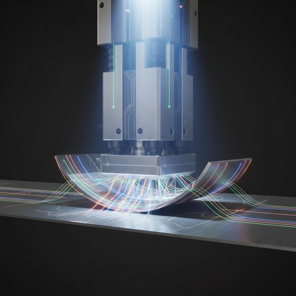
Manufacturing heavy-gauge crossmembers requires a robust stamping strategy that typically involves progressive or transfer die operations. The process begins with blanking, where the initial shape is cut from the coil, followed by piercing and complex forming stages. Given the heavy gauge of the material, maintaining flatness and controlling thickness reduction in critical bend radii is paramount.
One of the most sophisticated techniques in crossmember production is compensating for post-process deformation. During assembly, crossmembers are often welded to side rails, a process that introduces significant heat and potential distortion. Leading manufacturers address this by "over-bending" the part in the stamping die. This intentional deviation counteracts the expected heat distortion, ensuring the final assembly meets precise dimensional specifications. For OEMs requiring versatile production scales, manufacturers like Shaoyi Metal Technology offer stamping solutions ranging from rapid prototyping to mass production using presses up to 600 tons, bridging the gap between initial design validation and high-volume output.
Equipment capability is equally critical. Producing these heavy components often requires high-tonnage presses with rigid beds to minimize deflection. Ohio Valley Manufacturing notes that specialized heavy-gauge stamping capabilities are essential for producing durable frame rails and crossmembers for trucks and trailers, where material thickness exceeds standard automotive body sheet specs.
Manufacturing Challenges: Distortion, Springback, and Lubrication
Controlling physical dimensions throughout the production lifecycle is the primary challenge in stamping crossmembers. Beyond the immediate issue of springback in AHSS materials, the interaction between the stamping lubricant and downstream processes plays a vital role. Inefficient lubrication can lead to galling on the die, resulting in part defects and increased downtime.
Recent advancements in lubricant technology have shown that shifting from traditional emulsifiable oils to synthetic, polymer-based lubricants can yield significant operational improvements. Data indicates that optimizing the lubrication system can improve tool life by up to 15% while reducing overall fluid consumption. Furthermore, oil-free lubricants eliminate the need for rigorous pre-weld cleaning, as they do not generate the smoke or porosity issues associated with oil residues during welding.
Heat distortion remains a persistent variable. Since crossmembers often feature long weld seams—sometimes exceeding 5 meters in total length for complex subframes—the thermal energy input is substantial. The stamping process must produce parts that are not just dimensionally correct in isolation, but are engineered to absorb this thermal stress and result in a dimensionally accurate final assembly.
Quality Control and Assembly Integration
The final validation of a stamped crossmember extends beyond simple visual inspection. Coordinate Measuring Machines (CMM) and laser scanning are employed to verify that mounting points, such as the coupling jaws and suspension pick-up points, fall within tight tolerance windows. A deviation of even a few millimeters can prevent proper alignment of the suspension geometry, leading to poor vehicle handling or accelerated tire wear.
Surface finish is another critical quality metric, particularly for parts that will undergo e-coating or painting. Defects like burrs, splits, or draw marks can compromise corrosion resistance—a fatal flaw for underbody components exposed to road salt and moisture. Franklin Fastener emphasizes that the durability of structural and safety components relies on maintaining material integrity throughout the stamping process. Rigorous testing, including destructive weld checks and fatigue testing, ensures that the stamped crossmember will perform reliably over the vehicle's lifespan.
Future Outlook for Chassis Manufacturing
As the automotive industry continues its pivot toward electrification, the design and manufacturing of crossmembers are evolving. Electric vehicle (EV) architectures require crossmembers that can support heavy battery packs and protect high-voltage components, often necessitating even higher-strength materials and more complex geometries. The integration of stamping with other forming technologies, such as hydroforming, is likely to increase, offering engineers new ways to optimize chassis structures for the next generation of mobility.
Frequently Asked Questions
1. What are the main steps in the stamping method for crossmembers?
The stamping process for crossmembers typically involves seven key steps: blanking (cutting the initial shape), piercing (creating holes), drawing (forming deep shapes), bending (creating angles), air bending, bottoming/coining (for precision), and trimming. For heavy-gauge parts, these are often performed in a progressive die or transfer press setup to handle the material thickness and complexity.
2. Is metal stamping expensive for heavy components?
While metal stamping requires a significant upfront investment in tooling and dies, it is generally the most cost-effective method for high-volume production. The unit cost decreases dramatically as volume increases. For heavy components like crossmembers, the speed and repeatability of stamping outweigh the initial tooling costs compared to fabrication methods like machining or welding separate plates.
3. What is another name for a crossmember?
A crossmember is frequently referred to as a K-frame (especially in front suspension applications), a subframe, or an X-member, depending on its shape and location within the chassis. In truck applications, they may simply be called frame cross ties or structural traverses.