 Small batches, high standards. Our rapid prototyping service makes validation faster and easier —

Every Part Of CNC Machine Explained: From Bed To Control Panel
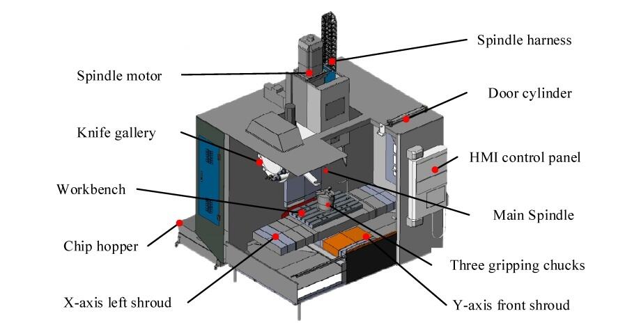
Understanding the Essential Parts of a CNC Machine
Imagine a machine that can transform a solid block of metal into a precision automotive component with tolerances measured in thousandths of an inch. That's the power of CNC machining—and it all comes down to understanding how each part of CNC machine works together in perfect harmony.
CNC (Computer Numerical Control) machines have become the backbone of modern precision manufacturing. From aerospace components to medical devices, these sophisticated systems rely on multiple interconnected parts to deliver consistent, high-quality results. But here's what many people overlook: the quality of each individual component directly determines what your machine can achieve.
Why Every Component Matters in Precision Manufacturing
Think of a CNC machine as an orchestra. The spindle, axes, controllers, and frame must all perform flawlessly—and in sync—to produce a masterpiece. When you understand the basic of cnc machine construction, you gain the ability to troubleshoot problems, evaluate equipment purchases, and communicate effectively with machinists and engineers.
Each part of a CNC machine serves a specific purpose:
- The machine bed absorbs vibrations and maintains stability
- The spindle drives cutting tools with precision rotation
- Linear guides ensure smooth, accurate movement along each axis
- The controller translates digital designs into physical motion
When any single component underperforms, it creates a ripple effect throughout the entire system. A slightly worn ball screw might seem minor—until you notice dimensional inaccuracies appearing in your finished parts.
The precision of your CNC output is only as good as your weakest component. Understanding how each part contributes to the whole system is the first step toward achieving manufacturing excellence.
The Building Blocks of Computer-Controlled Machining
So what exactly constitutes the components of a CNC machine? At its core, every CNC system includes structural elements (bed and frame), motion components (axes, motors, and drives), the cutting system (spindle and tooling), and the control system (controller and software). These cnc machine components work as an integrated unit where signals flow from the controller to the motors, translating G-code instructions into precise physical movements.
Whether you're evaluating a new machine purchase, troubleshooting an existing system, or simply seeking comprehensive cnc machine information, understanding these parts of machinery gives you a significant advantage. You'll know which specifications matter most for your applications and which features justify premium pricing.
In the sections ahead, we'll explore each major component in detail—from the foundational machine bed to the sophisticated control panel. You'll discover how these parts interact, what separates quality components from budget alternatives, and how to maintain them for optimal performance. Let's start with the foundation that holds everything together.
Machine Bed and Frame Foundations
Every precision machine part starts with a stable foundation. In CNC machining, that foundation is the machine bed—the structural backbone that supports all other cnc components and determines how accurately your machine can perform. Think of it this way: you wouldn't build a skyscraper on sand. Similarly, you can't achieve micron-level precision without a bed that absorbs vibrations and maintains dimensional stability under cutting forces.
The machine bed does more than simply hold parts of machines together. It provides the rigid base that keeps your spindle, worktable, and linear guides in perfect alignment throughout thousands of hours of operation. When cutting forces push against your workpiece, the bed must resist deflection. When spindle rotation creates vibration, the bed must dampen it before it reaches the cutting zone.
Cast Iron vs Welded Steel Frame Construction
Choosing between frame materials isn't just about cost—it's about matching the bed's properties to your machining requirements. Let's break down the three primary options you'll encounter when evaluating manufacturing machine parts:
Cast Iron remains the industry standard for good reason. Grade G3000 cast iron offers damping capacities 8-10 times greater than steel, meaning vibrations get absorbed rather than transmitted to your cutting tool. The graphite flakes within gray cast iron's microstructure act as natural vibration absorbers. However, cast iron is heavy and susceptible to thermal expansion—factors you'll need to consider for your specific application.
Welded Steel provides a lighter, more cost-effective alternative. Steel frames offer excellent rigidity and can be manufactured more quickly than cast components. The tradeoff? Lower vibration damping. Manufacturers compensate by adding internal ribbing or sandwich-like structures with damping layers. Steel works well for applications where speed matters more than ultimate surface finish.
Polymer Concrete (Mineral Casting) represents the newest evolution in bed technology. These composite materials deliver approximately 92% of cast iron's damping capacity at 30% reduced mass. They also excel at thermal stability—critical when temperature fluctuations could affect dimensional accuracy. The higher initial cost limits adoption, but for precision applications requiring tight tolerances, polymer concrete beds often justify the investment.
| Material | Rigidity | Vibration Damping | Thermal Stability | Weight | Cost |
|---|---|---|---|---|---|
| Cast Iron | High | Excellent | Moderate | Heavy | Moderate |
| Welded Steel | Moderate | Fair | Low | Light | Low |
| Polymer Concrete | Moderate | Excellent | High | Moderate | High |
How Bed Rigidity Affects Machining Accuracy
Here's where things get practical. Frame rigidity—measured by static stiffness—directly impacts what tolerances your machine can hold. Industrial-grade CNC machines typically achieve static stiffness of 50 N/μm or higher, meaning the bed deflects less than one micrometer for every 50 Newtons of applied force.
Why does this matter? When your cutting tool engages the workpiece, it generates significant force. If the bed flexes even slightly, that movement translates directly to dimensional error in your finished machine part. A well-designed bed maintains positional accuracy of 0.01mm/m or better under cutting forces up to 10kN.
Internal ribbing design plays a crucial role here. Cross-ribbed patterns distribute cutting forces more evenly than simple parallel ribs, providing better support in multiple directions. The size, thickness, and spacing of these ribs are calculated based on expected cutting forces and overall bed dimensions. Symmetric designs help balance forces, reducing the tendency for uneven stress and deformation.
Evaluating Machine Bed Quality
When assessing all machine parts on a new or used CNC machine, the bed deserves careful inspection. Here are the key quality indicators to examine:
- Material Grade Certification: Request foundry documentation proving material pedigree—Grade G3000 cast iron is the industry standard for optimal damping
- Surface Flatness: Guideways should be machined within a few micrometers to ensure smooth, accurate component movement
- Resonant Frequency: Target machines with resonant frequency above 80 Hz to avoid vibration amplification during cutting
- Thermal Deformation Tolerance: Look for specifications below 15 μm/m°C for applications requiring tight tolerances
- Ribbing Pattern: Examine internal structure for well-designed cross-ribbing that distributes stress evenly
- Heat Treatment Records: Annealing relieves internal stresses from casting, preventing long-term distortion
Regular maintenance extends bed life significantly. Monthly leveling checks, annual foundation bolt verification, and vibration spectrum analysis every 2,000 operating hours constitute standard practice. Machines with integrated way cover systems reduce debris-related wear by up to 65%.
With your machine's foundation understood, let's move upward to the component that actually removes material—the spindle.
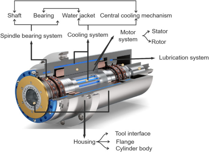
The Spindle and Its Critical Role in Material Removal
If the machine bed is the foundation, then the spindle is the heart of every CNC machine. This rotating assembly holds, drives, and positions your cnc tool with the precision needed to transform raw material into finished components. Every cut, every surface finish, every dimensional tolerance depends on how well your spindle performs its job.
The spindle's function sounds simple: rotate the cutting tool at the right speed with enough power to remove material. But achieving this consistently across thousands of hours of operation requires sophisticated engineering. Bearing configurations, motor integration, cooling systems, and balance specifications all contribute to spindle performance—and ultimately to the quality of your cnc milled parts.
Understanding spindle types helps you match the right cnc milling components to your specific applications. Let's explore the three primary spindle designs and discover where each excels.
Spindle Types and Their Ideal Applications
Belt-Driven Spindles represent the traditional approach to power transmission. A pulley and belt system transfers motor power to the spindle shaft, keeping the motor physically separated from the cutting zone. This separation offers a significant advantage: reduced heat transfer from the motor, which helps maintain accuracy during extended machining operations.
Belt-driven designs excel at delivering high torque at lower RPMs—exactly what you need when taking heavy cuts in steel or making deep passes through hardwood. They're also cost-effective and relatively easy to maintain. The tradeoff? The belt system can introduce vibration, produce more noise than other designs, and typically limits maximum spindle speed. For general metalworking, woodworking, and prototyping applications where ultimate precision isn't the primary concern, belt-driven spindles deliver excellent value.
Direct-Drive Spindles eliminate belts and pulleys entirely by connecting the motor shaft directly to the spindle shaft. This streamlined design reduces vibration sources, enabling higher precision and better surface finishes on your parts of a cnc mill.
Without mechanical power transmission losses, direct-drive spindles achieve faster RPMs and respond more quickly to speed change commands—ideal when your machining process involves frequent tool changes with varying speed requirements. Die and mold making, aerospace component machining, and precision work for medical and electronics industries all benefit from direct-drive characteristics. However, motor heat can transfer more readily to the spindle, often requiring liquid cooling systems to maintain thermal stability.
Motorized Spindles (also called integral or built-in spindles) take integration further by housing the motor inside the spindle assembly itself. This compact design delivers superior performance: extremely high speeds, minimal vibration, and exceptional precision. They're essential components of cnc milling machine configurations designed for high-speed machining.
Aerospace and automotive industries rely on motorized spindles for production efficiency. Precision grinding operations depend on their smooth rotation for mirror-like surface finishes. Medical device manufacturing uses them to create intricate implant geometries. The premium performance comes at a premium price—motorized spindles cost significantly more than other types and often require complete unit replacement rather than component-level repair.
| Spindle Type | Speed Range | Torque Output | Precision Level | Typical Applications |
|---|---|---|---|---|
| Belt-Driven | Low to Moderate (up to 8,000 RPM typical) | High at low RPM | Good | General metalworking, woodworking, prototyping, heavy cutting |
| Direct-Drive | Moderate to High (up to 15,000+ RPM) | Moderate | Very Good | Die/mold making, aerospace machining, precision manufacturing |
| Motorized | Very High (20,000-60,000+ RPM) | Lower at low RPM | Excellent | High-speed machining, precision grinding, medical components, engraving |
Understanding Spindle Speed and Torque Relationships
Here's where spindle selection gets interesting. Speed and torque exist in a fundamental relationship—and understanding this relationship helps you choose the right cnc milling parts for your work.
Torque represents rotational force—the spindle's ability to maintain cutting speed under load. When your tool engages hard material or takes a heavy cut, torque keeps the spindle rotating at the commanded speed. High-torque spindles excel at removing large volumes of material quickly.
Speed (measured in RPM) determines surface cutting velocity. Smaller diameter tools require higher RPMs to achieve optimal cutting speeds. Fine finishing operations, engraving, and working with small tools all demand high-speed capability.
The challenge? Most spindles can't maximize both simultaneously. Belt-driven designs favor torque at lower speeds. Motorized spindles favor speed but may struggle with heavy cuts at low RPM. Direct-drive spindles offer a middle ground, balancing both characteristics for versatile performance.
Bearing configuration directly influences what speeds your spindle can achieve. Angular contact bearings arranged in duplex or triplex configurations handle both radial and axial loads while supporting high-speed operation. Ceramic hybrid bearings reduce heat generation at extreme RPMs. The bearing preload—how tightly bearings are pressed together—affects both precision and maximum speed capability.
How Spindle Quality Affects Surface Finish and Tool Life
You might wonder why cnc milling machine components vary so dramatically in price. The answer often lies in spindle quality—and its direct impact on your results.
A precision-ground spindle with properly preloaded bearings runs with minimal runout (the amount of wobble at the tool tip). Runout under 0.0001 inches produces smoother surface finishes and extends tool life dramatically. Why? Because the cutting edge engages material more consistently, reducing the interrupted cutting action that causes premature tool wear.
Thermal stability matters equally. As spindles heat up during operation, components expand. Quality spindles incorporate cooling systems—either air or liquid—and use materials with matched thermal expansion rates to maintain precision as temperatures rise. Lesser spindles lose accuracy as they warm up, requiring compensation or frequent recalibration.
Vibration damping separates premium spindles from budget alternatives. Every spindle generates some vibration during rotation. Well-designed spindles incorporate balanced rotating assemblies and damping features that prevent vibration from reaching the cutting zone. The result? Better surface finishes and reduced chatter marks on your finished parts.
Maintenance Considerations for Spindle Longevity
Protecting your spindle investment requires consistent maintenance practices. Here's what matters most:
- Warm-up procedures: Run the spindle through a graduated warm-up cycle before production cutting—typically 10-15 minutes progressing from low to operating speed
- Lubrication monitoring: Check oil-air or grease lubrication systems daily; bearing failure from inadequate lubrication accounts for a significant percentage of spindle repairs
- Vibration analysis: Periodic vibration spectrum analysis detects bearing wear before catastrophic failure occurs
- Tool holder inspection: Worn or damaged tool holders cause runout that damages spindle bearings over time
- Coolant management: For liquid-cooled spindles, maintain proper coolant temperature and flow rates to prevent thermal damage
When spindles do require repair, the complexity varies by type. Belt-driven spindles often allow bearing replacement as a maintenance task. Motorized spindles typically require specialized repair facilities and may need complete unit replacement for internal motor failures.
With the spindle understood as the powerhouse driving material removal, let's examine the components that position that spindle precisely in three-dimensional space—the axis systems and linear motion components.
Axis Systems and Linear Motion Components
Now that you understand how the spindle removes material, let's explore what moves that spindle—and your workpiece—through three-dimensional space with micron-level precision. The axis systems and linear motion components are the cnc machine parts responsible for translating digital coordinates into physical movement. Without them, even the finest spindle would be useless.
Every cnc machine movement relies on a carefully orchestrated system of motors, screws, and guides working together. When your controller sends a command to move the cutting tool 0.001 inches to the left, these precision cnc components must execute that movement exactly—not 0.0009 inches, not 0.0011 inches, but precisely 0.001 inches. Understanding how these components achieve such accuracy helps you evaluate machines, diagnose problems, and appreciate the engineering behind modern CNC technology.
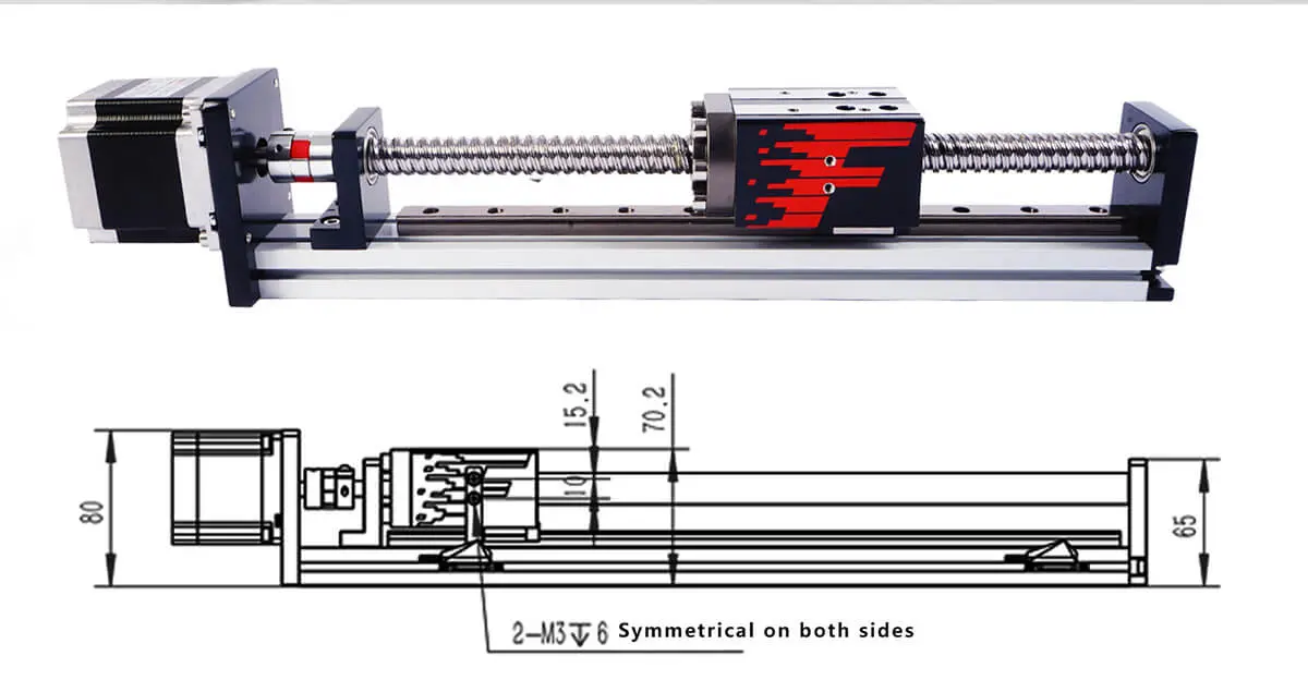
Ball Screws vs Lead Screws for Precision Movement
At the heart of linear motion sits a deceptively simple mechanism: a rotating screw that converts rotational motion into linear travel. But the way that conversion happens makes all the difference in your machine's performance. You'll encounter two primary technologies—ball screws and lead screws—each with distinct characteristics that suit different applications.
Ball screws represent the precision standard for serious CNC work. Inside a ball screw assembly, hardened steel balls roll between the screw shaft and nut, creating a low-friction interface that dramatically improves efficiency. According to industry specifications, this rolling motion reduces energy loss and increases force transmission efficiency to 90% or higher—compared to just 20-40% for sliding contact designs.
The recirculating ball design offers several advantages for cnc turning parts production and precision milling:
- Minimal backlash: Preloaded ball nuts eliminate the play between screw and nut, enabling precise bidirectional positioning
- High efficiency: Less friction means less heat generation and reduced motor power requirements
- Smooth operation: Rolling contact provides consistent movement without stick-slip behavior
- Long service life: Reduced friction translates to less wear over time
Lead screws take a simpler approach—the nut slides directly along the screw threads without rolling elements. This sliding friction creates more resistance but offers its own advantages. Lead screws cost significantly less than ball screws and provide inherent self-locking capability. When the motor stops, friction prevents the screw from back-driving—valuable for vertical axes where gravity could otherwise move the load.
When should you choose each type? Ball screws dominate applications requiring high precision, high speed, and extended duty cycles. CNC milling machines, lathes, and machining centers almost universally use ball screws on their primary axes. Lead screws find their place in lower-precision applications, hobbyist machines, 3D printers, and situations where self-locking behavior matters more than efficiency.
If you're examining a 3 axis cnc machine diagram, you'll typically see ball screws driving the X, Y, and Z axes. The screw's lead (distance traveled per revolution) determines the relationship between motor rotation and linear movement—smaller leads provide finer positioning resolution while larger leads enable faster traverse speeds.
Linear Guide Systems That Define Accuracy
Ball screws provide the driving force, but linear guides keep everything moving in a perfectly straight line. These guide systems support the moving components—tables, spindle heads, and carriages—while constraining motion to a single axis. Any deviation from perfect linear travel shows up as geometric error in your finished parts.
Modern CNC machines typically use linear ball guides (also called linear motion guides or LM guides). Similar to ball screws, these systems use recirculating balls to create rolling contact between the guide rail and carriage block. The result? Extremely low friction, high rigidity, and smooth motion even under heavy loads.
Linear guide specifications directly impact what tolerances your machine can hold. Key parameters include:
- Accuracy grade: Ranges from normal (N) to ultra-precision (UP), with tighter tolerances on rail straightness and carriage running parallelism
- Preload class: Light preload suits high-speed applications; heavy preload maximizes rigidity for heavy cutting
- Load capacity: Rated in static and dynamic load limits—must exceed your application requirements with appropriate safety margin
- Rigidity: Resistance to deflection under load, measured in N/μm
The arrangement of guide rails matters too. Most cnc machine drawing layouts show two parallel rails per axis, with multiple carriage blocks on each rail. This configuration provides moment load resistance—the ability to handle tilting forces without binding or losing accuracy. Wider rail spacing increases moment load capacity but requires more machine footprint.
Servo Motors: The Muscles Behind Precision Movement
Ball screws and linear guides handle the mechanical side of motion. But what actually drives the movement? That's where motors enter the picture—and the choice between motor types significantly affects machine capability.
Servo motors dominate professional CNC machines for good reason. These motors incorporate feedback systems that continuously monitor and adjust position, providing closed-loop control. When the controller commands movement to a specific coordinate, the servo system verifies the actual position and makes corrections in real-time. According to motor selection guidelines, servo motors offer higher performance and greater flexibility compared to alternatives, with precise control and high torque output.
Servo advantages include:
- High speed and acceleration capability
- Accurate positioning through encoder feedback
- Consistent torque across the speed range
- Dynamic response to changing loads
Stepper motors offer a more economical alternative for less demanding applications. They operate by stepping through discrete positions—typically 200 steps per revolution—making them suitable for applications requiring accurate control without the complexity of servo systems. Stepper motors work well in entry-level CNC routers, 3D printers, and hobby machines where cost matters more than ultimate performance.
The key difference? Servo systems know where they are; stepper systems assume they're where they should be. Under heavy loads or rapid acceleration, steppers can lose steps without the controller knowing—resulting in positioning errors. Servos detect and correct such errors automatically.
Axis Configurations: 3-Axis to 5-Axis Systems
How many axes does your application require? The answer determines both machine complexity and capability. Let's examine the common configurations:
3-Axis machines provide linear motion along X, Y, and Z axes—left/right, front/back, and up/down. This configuration handles the majority of milling, drilling, and routing operations. CNC mills, routers, and vertical machining centers commonly use 3-axis setups. The limitation? You can only access surfaces the tool can reach from above.
4-Axis machines add rotary motion, typically around the X-axis (called the A-axis) or around the Y-axis (B-axis). This additional freedom allows machining features on multiple sides of a part without manual repositioning. Cnc turning machine parts production often incorporates 4-axis capability for complex geometries.
5-Axis machines combine three linear axes with two rotary axes, enabling the cutting tool to approach the workpiece from virtually any angle. Complex aerospace components, turbine blades, and medical implants often require 5-axis capability to machine their intricate contours in a single setup.
Each additional axis adds complexity to the motion system. More ball screws, more guides, more motors, more encoders—and more potential sources of error that must be calibrated and maintained.
Component Specifications Across Machine Types
Different CNC machine types optimize their motion components for specific applications. The following table compares typical specifications across common machine categories:
| Component | CNC Mills | CNC Lathes | CNC Routers |
|---|---|---|---|
| Axis Travel (typical) | X: 500-1500mm, Y: 400-800mm, Z: 400-600mm | X: 200-600mm, Z: 300-1500mm | X: 1200-3000mm, Y: 1200-2000mm, Z: 150-300mm |
| Positioning Accuracy | ±0.005-0.01mm | ±0.005-0.01mm | ±0.05-0.1mm |
| Repeatability | ±0.002-0.005mm | ±0.002-0.005mm | ±0.02-0.05mm |
| Ball Screw Grade | C3-C5 precision ground | C3-C5 precision ground | C5-C7 rolled or ground |
| Linear Guide Type | High-rigidity roller or ball | Box ways or linear guides | Profile rail linear guides |
| Motor Type | AC servo | AC servo | Servo or stepper |
| Rapid Traverse Rate | 20-48 m/min | 20-30 m/min | 30-60 m/min |
Notice how routers prioritize large travel ranges and high traverse speeds over ultimate precision—they're designed for processing large sheet materials quickly. Mills and lathes sacrifice travel range for tighter tolerances required in precision metalworking.
How Component Interaction Affects Overall Accuracy
Here's what separates good machines from great ones: it's not just about individual component quality—it's about how well those components work together as a system.
Consider the error stack in a single axis movement. The ball screw contributes lead accuracy error. The linear guides add straightness error. The servo motor and encoder introduce positioning error. The coupling between motor and screw can add backlash. Temperature changes cause thermal expansion across all components. Each error source compounds the others.
Quality machine builders address this through:
- Component matching: Selecting components with compatible accuracy grades
- Precision assembly: Careful alignment during installation
- Volumetric compensation: Software correction for measured geometric errors
- Thermal management: Cooling systems and symmetric designs that minimize thermal distortion
When evaluating a CNC machine—whether from a cnc machine drawing or in person—look beyond individual specifications. Ask about the total positioning accuracy after assembly and compensation. That number reflects real-world performance better than component-level specifications alone.
With the motion systems understood, let's turn our attention to the component that coordinates all this movement—the control panel and CNC controller that serves as the machine's brain.
Control Panel and CNC Controller Systems
You've seen how the spindle removes material and how axis systems position everything precisely. But what coordinates all these movements? That's the job of the CNC controller—the brain that transforms digital instructions into physical motion. Understanding this part of CNC machine architecture helps you appreciate how cnc machine use has evolved from simple point-to-point positioning to sophisticated multi-axis contouring.
The controller doesn't work alone. It partners with the control panel—the physical interface where operators interact with the machine. Together, these components bridge the gap between cnc blueprints created in CAD/CAM software and the finished parts that roll off your machine. Let's explore how this critical partnership works.
Decoding the CNC Control Panel Interface
Walk up to any CNC machine and you'll encounter the control panel first. This interface serves as your command center for everything from loading programs to fine-tuning operations mid-cut. A well-designed cnc machine panel puts critical functions at your fingertips while keeping advanced settings accessible but unobtrusive.
What exactly will you find on a cnc milling machine control panel? The layout varies by manufacturer, but essential elements remain consistent across most machines:
- Display Screen: Shows program code, machine coordinates, active alarms, and operational status—modern machines feature high-resolution touchscreens for intuitive navigation
- Mode Selection Keys: Switch between automatic operation, manual jog, MDI (Manual Data Input), and editing modes
- Axis Jog Controls: Handwheels or buttons for manually positioning each axis during setup and tool changes
- Feed Rate Override: Rotary dial allowing real-time adjustment of programmed feed rates from 0-150% or more
- Spindle Speed Override: Similar dial for adjusting spindle RPM on the fly
- Cycle Start/Stop: Initiates and pauses program execution
- Emergency Stop (E-Stop): Large red mushroom button that immediately halts all machine motion
- Numeric Keypad: For entering coordinates, offsets, and program modifications
- Soft Keys: Context-sensitive buttons whose functions change based on current screen
The control panel cnc interface has evolved significantly. Early machines required operators to memorize cryptic button combinations. Today's panels feature graphical interfaces with simulation capabilities, conversational programming options, and even remote monitoring through connected devices. This evolution makes CNC technology accessible to a broader range of operators while still providing the depth experienced machinists demand.
How Controllers Translate Code into Motion
Behind the control panel lies the true intelligence: the CNC controller itself. Think of it as a specialized computer optimized for one critical task—converting programmed instructions into precisely coordinated motor movements. According to industry sources, the controller interprets G-code or M-code commands and converts them into exact electrical signals that drive motors and actuators.
Understanding cnc machine how it works at the controller level reveals a sophisticated process:
Step 1: Program Interpretation. The controller reads your G-code program—a standardized language where commands like G01 specify linear interpolation and G02 commands circular arcs. M-codes handle auxiliary functions like coolant activation and tool changes.
Step 2: Path Planning. For complex moves, the controller calculates intermediate positions using interpolation algorithms. A simple arc command might generate thousands of tiny linear segments that approximate the curved path with imperceptible deviation.
Step 3: Motion Coordination. Multiple axes must move simultaneously and arrive at the target position together. The controller calculates velocity profiles for each axis, managing acceleration and deceleration to achieve smooth, coordinated motion.
Step 4: Servo Loop Closure. Commands flow to servo drives, which power the motors. Encoders continuously report actual position back to the controller. This closed-loop system compares commanded position to actual position and makes corrections in real-time—typically thousands of times per second.
Step 5: Monitoring and Compensation. Throughout operation, the controller monitors for faults, compensates for known errors like backlash and thermal expansion, and adjusts parameters based on feedback from various sensors.
Major Controller Brands and Their Characteristics
The controller market features several dominant players, each with distinct philosophies and strengths. According to market analysis, FANUC and Siemens together hold approximately 45% of the global CNC controller market share.
FANUC (Japan) has built its reputation on reliability and widespread adoption. Their controllers power machines across virtually every manufacturing sector, making trained operators readily available. The consistent interface across product generations reduces retraining costs when upgrading equipment.
Siemens (Germany) offers powerful controllers known for sophisticated features and flexibility. Their SINUMERIK line excels in complex multi-axis applications and integrates tightly with broader factory automation systems—valuable for Industry 4.0 implementations.
Mitsubishi (Japan) provides controllers balancing performance with cost-effectiveness, particularly popular in Asian markets. Their systems integrate well with Mitsubishi servo drives and PLCs for complete motion solutions.
Heidenhain (Germany) specializes in high-precision applications, with controllers favored by mold makers, die shops, and aerospace manufacturers who demand the tightest tolerances.
Mazak and Haas produce proprietary controllers for their own machine tools. The Mazak MAZATROL and Haas NGC systems feature user-friendly interfaces that simplify operation—making them popular choices for shops training new operators.
How Controller Quality Affects Results
Why do controller specifications matter for your machining outcomes? The answer lies in processing speed, interpolation sophistication, and feedback resolution.
A capable controller delivers precise motion control through advanced algorithms that smoothly interpolate complex paths. It compensates for real-world factors such as backlash and temperature variations while continuously monitoring safety conditions. When the controller performs well, every other part of CNC machine can reach its full potential.
Processing speed determines how quickly the controller can read program blocks and calculate motion commands. High-speed machining applications demand controllers that can look ahead hundreds or thousands of blocks, optimizing velocity profiles to maintain smooth motion through complex contours.
Feedback resolution affects positioning precision. Controllers working with high-resolution encoders can detect and correct smaller positioning errors. Combined with advanced servo tuning algorithms, this enables the tight tolerances precision manufacturing demands.
Operator efficiency also depends on controller design. Intuitive interfaces reduce programming time. Powerful simulation capabilities catch errors before cutting starts. Remote monitoring features enable oversight of multiple machines simultaneously. These productivity factors often justify premium controller pricing through reduced cycle times and fewer scrapped parts.
With the brain of your CNC machine understood, let's examine the components that actually grip your workpiece and hold your cutting tools—the tooling and workholding systems that complete the machining equation.
Tooling and Workholding Components
Your spindle spins, your axes move precisely, and your controller orchestrates everything perfectly. But none of that matters if you can't securely grip your workpiece and cutting tools. Tooling and workholding components are the machine tool parts that bridge the gap between your machine's capabilities and actual material removal. These cnc machined components determine whether your finished part meets specifications or ends up in the scrap bin.
Think about it this way: even a $500,000 machining center produces garbage if the workpiece shifts mid-cut or the tool holder vibrates excessively. Understanding tooling for cnc machines helps you select the right solutions for your applications—and recognize when tooling quality is limiting your results.
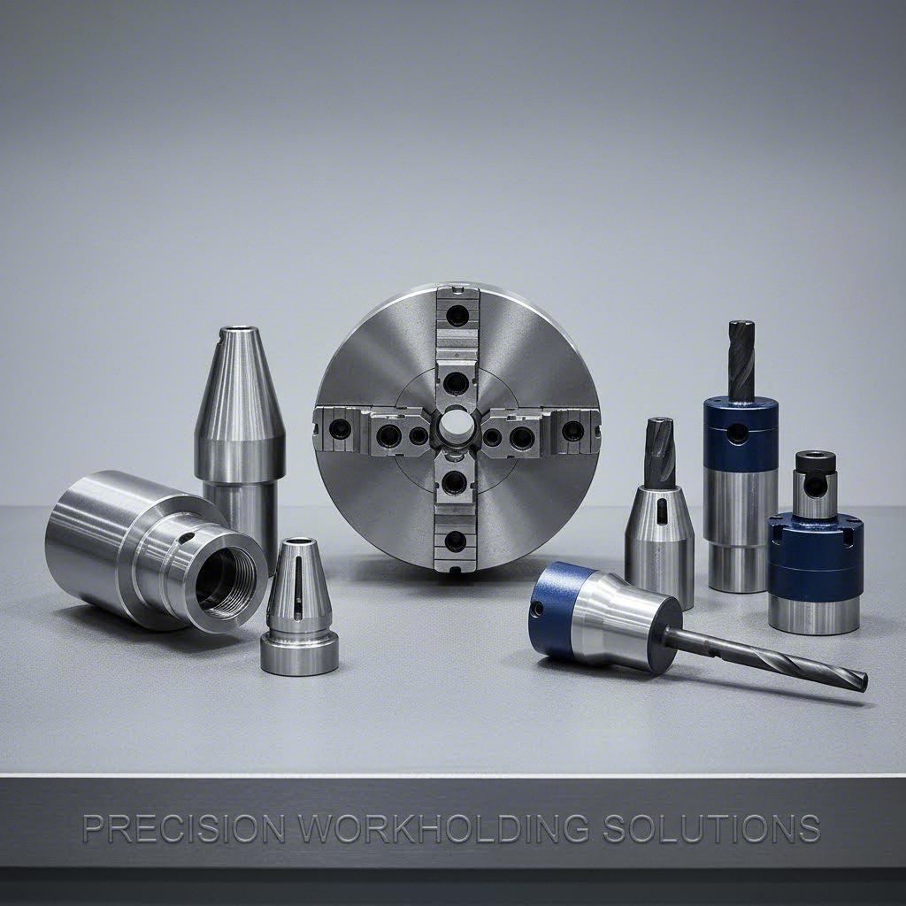
Selecting the Right Chuck for Your Workpiece
Let's start by answering a fundamental question: what exactly is a chuck? To define chucks simply, they're clamping devices mounted on the spindle that grip and rotate workpieces during machining operations. According to industry guidelines, a proper chuck is essential for ensuring accurate positioning and preventing vibration, deformation, or slippage during cutting, drilling, or finishing operations.
The parts of cnc lathe configurations almost universally include a chuck as the primary workholding device. But which type suits your application? Here's what you need to know about the major categories:
Three-Jaw Universal Chucks are the workhorses of lathe cnc parts. The three jaws, spaced 120 degrees apart, move simultaneously toward the center—automatically centering round or hexagonal stock. This self-centering action makes setup fast and straightforward. The tradeoff? Limited clamping strength compared to other designs, and centering precision can degrade with wear over time. For general turning of round bars, three-jaw chucks deliver excellent value.
Four-Jaw Independent Chucks offer maximum flexibility. Each jaw adjusts independently, allowing you to grip square, rectangular, and irregular shapes that three-jaw chucks simply cannot handle. You can also dial in precise centering for off-center or eccentric machining operations. The downside? Setup takes longer because you must adjust each jaw individually and verify centering with a dial indicator. Experienced machinists reach for four-jaw chucks when workpiece geometry demands it.
Collet Chucks excel at precision and repeatability. A collet is a slotted collar that contracts uniformly around the workpiece when tightened, distributing clamping pressure evenly. This design minimizes distortion on delicate parts and provides exceptional concentricity—critical for parts of a cnc lathe producing high-tolerance components. The limitation? Each collet fits a narrow size range, so you'll need a set of collets to accommodate different diameters. For production bar feeding where the same diameter runs repeatedly, collet chucks maximize efficiency and accuracy.
Magnetic Chucks use electromagnetic or permanent magnets to hold ferromagnetic workpieces without mechanical clamping pressure. This approach eliminates distortion entirely—ideal for thin or delicate parts that traditional jaws would deform. However, magnetic chucks only work with magnetic materials like steel and iron, and they cannot resist the rotational forces of heavy cutting operations.
Hydraulic and Pneumatic Power Chucks automate the clamping process using fluid or air pressure. These systems deliver consistent clamping force, rapid actuation, and easy integration with automatic loading systems. High-volume production environments rely on power chucks to minimize cycle times and maintain repeatability across thousands of parts.
Tool Holder Systems That Maximize Rigidity
While chucks grip your workpiece, tool holders secure your cutting tools to the spindle. The connection between tool holder and spindle directly affects rigidity, runout, and ultimately surface finish quality. A weak link here undermines everything else your machine does well.
Several tool holder systems compete in the market, each optimized for different priorities:
CAT (V-Flange) Holders remain the North American standard for machining centers. The tapered shank seats into the spindle taper, while a retention knob pulls the holder firmly into position. CAT holders provide good rigidity for general machining but can lose clamping force at high spindle speeds as centrifugal force expands the spindle taper.
BT Holders follow similar principles but use metric dimensions and symmetrical construction. The balanced design makes BT holders preferred for higher-speed applications where runout matters more.
HSK (Hollow Shank Taper) Holders address high-speed limitations through face-and-taper contact. The hollow shank expands under clamping force, pressing against both the taper and the spindle face simultaneously. This dual contact maintains rigidity even at elevated RPMs and provides more consistent tool positioning. HSK has become the standard for high-speed machining applications.
Collet Chucks and ER Collet Systems offer versatility for holding round-shank tools. The spring collet compresses around the tool shank, providing good grip and reasonable concentricity. ER collets accommodate a range of shank diameters within each collet size, reducing the inventory required.
Shrink-Fit Holders deliver the ultimate in rigidity and runout performance. The holder bore is slightly undersized; heating expands it enough to accept the tool shank, and cooling creates an interference fit that grips with tremendous force. Runout values under 0.0001 inches are achievable. The precision comes at a cost—you need heating equipment, and tool changes take longer than quick-change systems.
Hydraulic Holders use oil pressure within the holder body to clamp the tool shank. They provide excellent runout, good vibration damping, and accommodate slight shank diameter variations. Hydraulic holders balance precision with convenience, making them popular for finishing operations where surface quality matters.
Comparing Tooling Options for Your Applications
Selecting the right tooling involves balancing precision requirements, cost constraints, and application demands. The following comparison helps guide your decisions:
| Tooling Type | Precision Level | Cost Consideration | Ideal Applications |
|---|---|---|---|
| Three-Jaw Chuck | Good (±0.001-0.003") | Low to Moderate | General turning of round/hex stock, prototype work |
| Four-Jaw Chuck | Excellent (operator dependent) | Moderate | Irregular shapes, eccentric machining, precision centering |
| Collet Chuck | Excellent (±0.0005" or better) | Moderate (plus collet sets) | Production bar work, precision turning, small diameters |
| CAT/BT Holders | Good (±0.0002-0.0005") | Low to Moderate | General milling, drilling, moderate-speed applications |
| HSK Holders | Very Good (±0.0001-0.0003") | Moderate to High | High-speed machining, precision milling, aerospace |
| Shrink-Fit Holders | Excellent (±0.0001" or better) | High (plus heating equipment) | Finish milling, die/mold work, micro-machining |
| Hydraulic Holders | Very Good (±0.0001-0.0002") | Moderate to High | Finishing operations, vibration-sensitive cutting |
Automatic Tool Changers: Productivity Through Automation
Modern machining centers rarely stop at holding a single tool. Automatic tool changers (ATCs) store multiple tools and swap them into the spindle automatically—often in seconds. This capability transforms machining from a series of manual interventions into a continuous, lights-out operation.
ATCs vary in capacity from simple 10-tool carousels to massive chain-type magazines holding 100+ tools. The changer mechanism must position tools precisely and execute exchanges quickly without damaging delicate cutting edges. Integration with the controller ensures the right tool loads for each operation, verified by tool presence sensors and length measurement probes.
For shops running diverse parts, generous tool capacity eliminates the setup time otherwise spent loading and unloading tools between jobs. The productivity gains often justify the additional investment in larger tool magazines.
Evaluating Tooling Quality
How do you distinguish quality tooling from budget alternatives? The differences may not be obvious visually, but they show up clearly in machining results. Here's what to evaluate:
- Runout Specifications: Quality holders specify guaranteed runout values—typically ±0.0002" or better for precision work
- Balance Grade: High-speed applications require balanced holders (G2.5 or better at operating speed) to prevent vibration
- Material Quality: Premium holders use hardened, precision-ground steel with proper heat treatment for durability
- Taper Accuracy: The taper angle and surface finish determine how precisely the holder seats in the spindle
- Repeatability: Quality tooling maintains its specifications through thousands of tool changes
- Manufacturer Reputation: Established brands stake their reputation on consistent quality—a form of insurance for your investment
According to workholding experts, by selecting the right workholding solution, machinists can improve precision, efficiency, and overall productivity in their CNC operations. The same principle applies to tool holders—investing in quality tooling pays dividends through better parts, longer tool life, and reduced troubleshooting time.
With your tooling and workholding fundamentals understood, maintaining these components—along with all the other critical systems we've covered—becomes the next priority. Let's explore the maintenance practices that keep every part of your CNC machine performing at its best.
Maintenance and Troubleshooting for CNC Components
You've invested significantly in your CNC machine—now how do you protect that investment? Understanding the parts of cnc machine is only half the equation. Keeping those cnc machines parts performing at peak efficiency requires a systematic approach to maintenance and the ability to recognize problems before they become catastrophic failures.
Here's a reality check: according to maintenance experts, neglecting CNC maintenance takes a hard hit on performance, production schedules, and quality. When cnc mechanical parts aren't properly maintained, tolerances drift, deviations appear, and flaws show up in finished products. The good news? Most failures are preventable with proper attention to maintenance schedules and early warning signs.
Preventive Maintenance Schedules by Component
Different parts of cnc machines require different maintenance intervals. Some components need daily attention while others can go months between service. The following table organizes essential maintenance tasks by component, helping you build a comprehensive preventive maintenance program:
| Component | Maintenance Task | Frequency | Criticality |
|---|---|---|---|
| Spindle | Check for unusual noise or vibration during warm-up | Daily | High |
| Spindle | Verify lubrication system operation (oil-air or grease) | Daily | High |
| Spindle | Inspect taper for wear, scoring, or contamination | Weekly | High |
| Spindle | Perform vibration spectrum analysis | Quarterly | Medium |
| Linear Guides | Wipe exposed surfaces and remove debris | Daily | Medium |
| Linear Guides | Check lubrication levels and distribution | Weekly | High |
| Linear Guides | Inspect for scoring, pitting, or unusual wear patterns | Monthly | Medium |
| Ball Screws | Apply manufacturer-recommended grease | Per schedule (typically 500-1000 hours) | High |
| Ball Screws | Run backlash measurement program and record values | Monthly | High |
| Ball Screws | Inspect for contamination and debris infiltration | Weekly | Medium |
| Coolant System | Check coolant concentration and pH levels | Daily | Medium |
| Coolant System | Clean filters and inspect pumps | Weekly | Medium |
| Coolant System | Drain, clean tank, and replace coolant | Monthly to Quarterly | Medium |
| Way Covers | Inspect for damage, proper sealing, and chip accumulation | Daily | Medium |
| Control Panel | Clean display and check button/switch operation | Weekly | Low |
| Electrical Connections | Inspect wiring for damage and verify tight connections | Monthly | High |
| Axis Alignment | Verify X, Y, Z alignment using dial indicators or laser | Quarterly to Annually | High |
Why does following a schedule matter so much? According to troubleshooting guides, prevention is often the linchpin of efficient maintenance. Regular inspection, lubrication, checks for loose connections, and maintaining cleanliness are fundamental practices that contribute to the longevity of CNC machines.
Recognizing Early Warning Signs of Component Wear
Even with perfect maintenance schedules, components eventually wear. The key is catching problems early—before a minor issue becomes a major repair bill or production stoppage. Here's what to watch for across your critical cnc spare parts:
Spindle Warning Signs:
- Unusual noise during operation—grinding, squealing, or rumbling indicates bearing distress
- Excessive heat at the spindle nose compared to normal operating temperature
- Vibration that wasn't present before, especially at specific RPM ranges
- Degraded surface finish on parts that previously machined well
- Increased runout at the tool tip measured with a dial indicator
Ball Screw Warning Signs:
According to ball screw specialists, understanding common failure modes is crucial for identifying potential issues early. Watch for:
- Increasing backlash values in your measurement program—indicates internal wear
- Rough or inconsistent motion when jogging axes slowly
- Unusual noise from the ball nut area during movement
- Visible contamination or debris near ball screw seals
- Positioning errors that weren't present previously
Linear Guide Warning Signs:
- Visible scoring or wear marks on rail surfaces
- Increased resistance during manual axis movement
- Stick-slip motion at low feed rates
- Lubricant discoloration indicating contamination or breakdown
- Play or looseness when checking carriage blocks by hand
Common Failure Modes and Prevention
Understanding why components fail helps you prevent those failures. Here are the most common culprits across cnc repair parts categories:
Inadequate Lubrication tops the list. Whether it's spindle bearings, ball screws, or linear guides, insufficient lubrication causes friction, heat, and accelerated wear. Prevention means establishing and following strict lubrication schedules using manufacturer-specified lubricants. For high-demand applications, automatic lubrication systems eliminate human error from the equation.
Contamination causes premature wear across multiple component types. Metal chips, dust, and coolant infiltrating ball screws or linear guides create abrasive conditions that rapidly degrade precision surfaces. Prevention involves maintaining seals and way covers, keeping the work area clean, and using proper chip evacuation systems.
Overloading stresses components beyond their design limits. This applies to spindles running tools too aggressively, ball screws handling forces exceeding their ratings, or chucks gripping beyond their capacity. Prevention means understanding component specifications and programming within those limits—even when production pressure tempts you to push harder.
Misalignment creates uneven wear patterns and accelerates component degradation. When axes aren't properly squared or ball screws aren't aligned with their support bearings, certain areas experience excessive stress while others remain underloaded. Regular alignment verification catches drift before damage accumulates.
Troubleshooting Common Issues
When problems do occur, systematic troubleshooting saves time and prevents misdiagnosis. Follow these steps when investigating any cnc machine part issue:
- Step 1: Observe and Document — Carefully note the machine's behavior, when the problem started, any recent changes or maintenance, and specific circumstances when the problem occurs
- Step 2: Check the Basics First — Verify lubrication levels, inspect for obvious contamination, confirm electrical connections are secure, and review recent error logs
- Step 3: Isolate the Problem — Systematically narrow down potential causes by testing individual components and reviewing diagnostic data
- Step 4: Consult Documentation — Manufacturers provide troubleshooting guides and technical support—use these resources for insights into common issues and recommended solutions
- Step 5: Implement Solutions — Once the cause is identified, make the appropriate repair—whether replacing damaged components, adjusting settings, or recalibrating
- Step 6: Test and Verify — After implementing solutions, thoroughly test the machine to ensure the problem is resolved and monitor performance going forward
For persistent or complex issues, don't hesitate to contact equipment manufacturers or specialized service providers. Their expertise with specific parts of cnc machine systems often identifies root causes that generalized troubleshooting misses.
Building a Maintenance Culture
The most effective maintenance programs extend beyond checklists. They create a culture where operators actively participate in machine care. Train your team to recognize abnormal sounds, monitor for unusual behavior, and report concerns before small issues escalate. According to maintenance experts, investing in comprehensive training programs for both operators and maintenance staff holds significant benefits for overall efficiency and reliability.
Document everything. Maintain detailed logs of maintenance activities and issues encountered. Analyzing patterns over time reveals recurring problems and guides development of targeted preventive measures. This data-driven approach transforms maintenance from reactive firefighting into proactive asset management.
With proper maintenance practices in place, your CNC components deliver years of reliable service. But how do these components differ across various machine types? Understanding those variations helps you apply the right maintenance approach—and make informed decisions when expanding your capabilities.
Component Differences Across CNC Machine Types
You've learned about spindles, axes, controllers, and tooling—but here's what most resources overlook: these components look and perform very differently depending on whether they're installed in a milling machine, lathe, or router. Understanding these variations isn't just academic knowledge. It's essential when you're evaluating equipment purchases, troubleshooting cross-platform issues, or expanding your shop's capabilities.
Think about it this way: a spindle designed for a CNC router would fail catastrophically in a heavy-duty milling application. The cnc milling machine parts optimized for cutting steel aren't the same as cnc router components engineered for carving wood. Let's break down exactly how each major tool machine category configures its components differently—and why those differences matter for your operations.
Component Variations Across CNC Mills and Lathes
CNC mills and lathes represent the two foundational approaches to material removal—and their component configurations reflect fundamentally different machining philosophies.
Spindle Design Differences: In a CNC mill, the spindle holds and rotates the cutting tool while the workpiece remains stationary on the table. This configuration demands spindles optimized for high-speed operation with various tool sizes. According to spindle specialists, CNC spindles support high-speed, high-precision machining with features like automatic tool changes, programmable operations, and rigid tapping capabilities.
The cnc lathe parts take the opposite approach. Here, the spindle rotates the workpiece while cutting tools remain relatively stationary on a turret or tool post. Lathe spindles prioritize torque over speed—you need serious rotational force to turn heavy steel bar stock. Traditional lathe spindles feature simpler structures compared to their milling counterparts, focusing on low-speed heavy-duty cutting and basic machining operations.
Axis Configuration Differences: CNC mills typically operate with three primary linear axes (X, Y, Z), with the spindle moving vertically while the table moves horizontally. More advanced configurations add rotary axes (A, B, or C) for 4-axis and 5-axis capability. The cnc lathe components configure axes differently—the X-axis controls tool movement toward or away from the workpiece centerline, while the Z-axis controls movement along the workpiece length. Many lathes add a C-axis for spindle positioning and live tooling operations.
Controller Requirements: While both machine types use similar controller architectures, the software and interpolation algorithms differ significantly. Lathe controllers must handle threading cycles, constant surface speed calculations, and turning-specific canned cycles. Mill controllers focus on pocket milling, circular interpolation, and multi-axis contouring. According to industry comparisons, choosing between these machines depends heavily on part geometry—cylindrical parts favor lathes while complex geometrical shapes require mills.
How Router Components Differ from Machining Centers
CNC routers might look similar to milling machines at first glance, but the parts of cnc router systems are engineered for entirely different priorities. Understanding these distinctions prevents costly misapplication of equipment.
Structural Components: Routers typically feature gantry-style construction where the spindle moves over a stationary table. This configuration accommodates the large sheet materials—plywood panels, plastic sheets, composite boards—that routers process. The frame construction emphasizes spanning large work areas rather than resisting heavy cutting forces. While machining centers use box-way or heavy linear guide systems for maximum rigidity, router linear motion systems prioritize speed and travel range over ultimate stiffness.
Spindle Characteristics: Router spindles run faster but with less torque than their machining center counterparts. According to machining experts, CNC routers are typically designed for larger, flatter workpieces and softer materials like wood, plastics, and composites. The spindle specifications reflect this—you'll see maximum speeds reaching 24,000 RPM or higher, but torque ratings that would struggle with aggressive metal cutting.
Motion System Priorities: The cnc router components prioritize rapid traverse speeds and large travel ranges over positioning accuracy. While a machining center might achieve ±0.005mm positioning accuracy, a router typically specifies ±0.05-0.1mm—perfectly acceptable for sign making and woodworking but inadequate for precision metalwork. Ball screw grades, encoder resolutions, and servo tuning all reflect these different accuracy requirements.
Workholding Approaches: Here's where differences become immediately visible. Machining centers use vises, fixtures, and chucks to clamp individual parts rigidly. Routers typically employ vacuum tables that use suction to hold flat sheet materials in place—no mechanical clamping required. This workholding approach works brilliantly for the router's intended applications but would never provide adequate holding force for heavy metal cutting.
Comprehensive Component Comparison Across Machine Types
The following table consolidates key component specifications across the major CNC machine categories. Use this comparison when evaluating equipment for specific applications or understanding why certain machines excel at particular tasks:
| Component | CNC Milling Machine | CNC Lathe | CNC Router | 5-Axis Machining Center |
|---|---|---|---|---|
| Spindle Speed Range | 6,000-15,000 RPM typical | 2,000-6,000 RPM typical | 12,000-24,000+ RPM | 10,000-42,000 RPM |
| Spindle Power | 5-30 kW | 7-45 kW | 2-15 kW | 15-40 kW |
| Spindle Type | Belt-driven or direct-drive | Belt-driven or gear-driven | Direct-drive or motorized | Motorized (built-in motor) |
| Primary Axes | X, Y, Z (linear) | X, Z (linear); C (rotary) | X, Y, Z (linear) | X, Y, Z + A, B or A, C |
| Typical Travel Range | 500-1500mm per axis | X: 200-600mm, Z: 300-1500mm | 1200-3000mm+ per axis | 500-1500mm per axis |
| Positioning Accuracy | ±0.005-0.01mm | ±0.005-0.01mm | ±0.05-0.1mm | ±0.003-0.008mm |
| Ball Screw Grade | C3-C5 precision ground | C3-C5 precision ground | C5-C7 rolled or ground | C3 precision ground |
| Linear Guide Type | Roller or ball linear guides | Box ways or linear guides | Profile rail guides | High-rigidity roller guides |
| Rapid Traverse | 20-48 m/min | 20-30 m/min | 30-60 m/min | 30-60 m/min |
| Primary Workholding | Vises, fixtures, clamps | Chucks, collets, faceplates | Vacuum table, clamps | Vises, fixtures, trunnion tables |
| Tool Change System | 10-40 tool carousel/arm | 8-12 tool turret | Manual or simple ATC | 30-120+ tool magazine |
| Ideal Materials | Metals, plastics, composites | Metals, plastics (round stock) | Wood, plastics, aluminum, foam | Aerospace alloys, complex metals |
| Frame Construction | Cast iron C-frame or bridge | Cast iron slant or flat bed | Welded steel gantry | Cast iron or polymer concrete |
Multi-Axis Machines: Where Component Complexity Peaks
Five-axis machining centers represent the pinnacle of CNC component integration. Every element—from spindle to controller—must perform at elevated specifications to achieve the complex contouring these machines deliver.
Rotary Axis Components: The additional A and B (or C) axes introduce rotary tables or trunnion systems that must match the precision of linear axes. These components include high-accuracy rotary encoders, precision worm gear or direct-drive mechanisms, and sophisticated clamping systems that lock positions during cutting while allowing smooth rotation during positioning moves.
Controller Sophistication: Five-axis controllers must simultaneously coordinate five motion streams while managing tool center point control (TCPC), which automatically adjusts linear axis positions as rotary axes move to keep the tool tip at the programmed location. This computational complexity demands more powerful processors and more sophisticated interpolation algorithms than three-axis machines require.
Spindle Requirements: Multi-axis machines often approach workpieces from unusual angles, requiring spindles with excellent accessibility. Compact spindle head designs minimize interference with workpieces and fixtures. The cnc lathe machine parts for multi-tasking mill-turn machines combine lathe-style main spindles with milling spindles—essentially integrating components from both machine categories into a single platform.
Matching Components to Applications
So how do you apply this knowledge? When evaluating any major tool machine purchase or capability expansion, consider these component-level questions:
- What materials will you process? Hard metals demand rigid frames, powerful spindles, and precision ball screws. Soft materials like wood and plastics tolerate lighter construction.
- What tolerances do your parts require? Precision work needs ground ball screws, high-resolution encoders, and thermally stable construction. General work allows more economical component grades.
- What part geometries will you produce? Cylindrical parts point toward lathe configurations. Complex 3D surfaces require multi-axis milling capability. Flat sheet processing suits router construction.
- What production volumes do you expect? High-volume production justifies automatic tool changers, power workholding, and robust components rated for continuous duty.
Understanding how components vary across machine types transforms you from a passive equipment user into an informed decision-maker. You'll recognize when a machine's specifications match your application—and when apparent bargains actually represent mismatched capabilities that will limit your results.
With this comprehensive understanding of how components function and differ across machine types, you're equipped to make informed manufacturing decisions. Let's explore how to apply this knowledge when evaluating machining partners and making procurement choices.
Applying Component Knowledge to Manufacturing Decisions
You now understand how every part of a machine contributes to CNC performance—from the vibration-dampening bed to the precision-coordinating controller. But here's where that knowledge becomes truly valuable: translating technical understanding into practical decision-making when selecting machining partners or procuring cnc machining parts for your projects.
Think about it this way. When you evaluate a potential manufacturing partner, you're not just looking at quoted prices and lead times. You're assessing whether their equipment can actually deliver the tolerances your cnc parts require. Your component knowledge transforms you from a passive buyer into an informed evaluator who asks the right questions and recognizes quality indicators that others miss.
From Component Knowledge to Quality Assessment
How do you connect what you've learned about machining components to real-world quality outcomes? Start by understanding that every specification on your finished cnc machining part traces back to specific machine and parts capabilities.
Consider surface finish requirements. That 32 Ra microinch finish specification? It depends on spindle runout, vibration damping, and tooling rigidity working together. A shop running worn spindle bearings or budget tool holders simply cannot achieve premium surface finishes—regardless of what their sales team promises.
Dimensional tolerances follow similar logic. When your drawing calls for ±0.001" positioning accuracy, you need a machine with precision-ground ball screws, high-resolution encoders, and properly calibrated axes. According to industry evaluation guidelines, precision in CNC machining is defined by how closely the machined part matches the design specifications, with tolerance ranges typically measured in microns or millimeters.
Here's what separates informed buyers from everyone else: they evaluate potential partners based on equipment specifications, not just promises. They ask about:
- Machine age and condition: Newer equipment with documented maintenance histories typically delivers tighter tolerances
- Spindle specifications: Maximum speed, runout values, and recent service records indicate capability for precision work
- Axis accuracy: Positioning accuracy and repeatability specifications reveal what tolerances the machine can reliably hold
- Tooling systems: Quality tool holders and workholding equipment directly impact part accuracy
- Measurement capabilities: CMM equipment and in-process inspection tools verify that quality claims are backed by data
Evaluating Manufacturing Partners Through Machine Specifications
When you're sourcing cnc part production, the evaluation process goes beyond reviewing sample parts. Smart procurement professionals assess the entire manufacturing system—because that system determines whether quality will be consistent across your entire order, not just the samples they cherry-picked for your review.
According to certification experts, formal certifications assure clients and stakeholders of a company's commitment to quality at every step. But certifications alone don't tell the whole story. You need to understand what those certifications actually require in terms of machine and parts management.
Quality Management Certifications Matter: Industry certifications indicate systematic approaches to quality control. ISO 9001 establishes baseline quality management practices. For automotive applications, IATF 16949 certification raises the bar significantly—requiring statistical process control, measurement system analysis, and continuous improvement protocols that directly affect how machining components are maintained and monitored.
Consider how this works in practice. A facility operating under IATF 16949 requirements doesn't just check parts after machining—they monitor process capability in real-time. Statistical Process Control (SPC) tracks dimensional trends, identifying when machine components begin drifting before out-of-tolerance parts get produced. This proactive approach protects your production schedule from surprise quality issues.
For example, Shaoyi Metal Technology demonstrates how component-level quality management translates to manufacturing excellence. Their IATF 16949 certification and SPC implementation ensure that precision CNC machining for automotive applications maintains consistency across production runs. High-tolerance components result from properly maintained machine parts combined with rigorous process monitoring—not luck or exceptional operator skill on any given day.
Questions That Reveal True Capability: According to industry recommendations, selecting the right CNC machining partner is one of the most important decisions you can make for your project. Ask potential partners these component-focused questions:
- What CNC equipment do you use, and what are the positioning accuracy specifications?
- How often do you calibrate your machines, and can you provide calibration records?
- What preventive maintenance schedule do you follow for spindles, ball screws, and linear guides?
- What inspection equipment do you use to verify part dimensions?
- Can you provide Cpk data demonstrating process capability for similar tolerance requirements?
Partners who answer these questions confidently—with documentation to back their claims—demonstrate the component-level attention that produces reliable cnc machining part quality.
Quality Indicators When Evaluating CNC Machining Partners
Not every manufacturer deserves your business. Here are the key quality indicators that separate capable partners from those who will disappoint:
- Documented Equipment Specifications: Quality shops know their machine capabilities and share specifications openly—including tolerance ranges, repeatability values, and surface finish capabilities
- Preventive Maintenance Programs: Ask about maintenance schedules and records; shops that invest in component care deliver more consistent results
- Inspection Capabilities: CMM equipment, surface roughness testers, and documented inspection procedures indicate commitment to verification, not just production
- Industry-Specific Certifications: IATF 16949 for automotive, AS9100 for aerospace, ISO 13485 for medical—these certifications require documented quality systems
- Statistical Process Control: SPC implementation shows proactive quality management rather than reactive sorting of good parts from bad
- Traceability Systems: The ability to trace any part back to specific machines, operators, and material lots indicates mature quality systems
- Sample Part Quality: Request sample machining that matches your actual requirements—not simplified demonstration pieces
- Reference Customers: Established partners willingly provide references from customers with similar precision requirements
Making Your Component Knowledge Work for You
Your understanding of CNC machine components gives you a significant advantage in manufacturing decisions. You can now evaluate equipment purchases with technical insight rather than relying solely on salesperson claims. You can assess potential machining partners based on their equipment capabilities and maintenance practices. And you can communicate more effectively with machinists and engineers because you understand the factors that determine part quality.
Whether you're specifying cnc parts for a new product, troubleshooting quality issues with existing suppliers, or investing in your own CNC equipment, component knowledge transforms abstract specifications into practical understanding. You know that surface finish depends on spindle condition and tooling quality. You understand that tight tolerances require precision ball screws and calibrated axes. You recognize that consistent quality comes from maintained machines and controlled processes.
That knowledge is your competitive advantage. Use it to make informed decisions that deliver the quality your applications demand—and build partnerships with manufacturers whose component-level attention matches your precision requirements.
Frequently Asked Questions About CNC Machine Parts
1. What are the 7 major parts of a CNC machine?
The seven major parts of a CNC machine include the Machine Control Unit (MCU) that interprets G-code commands, input devices for program loading, the drive system with servo motors and ball screws, machine tools including the spindle and cutting implements, the feedback system with encoders for position verification, the bed and table providing structural foundation, and the cooling system managing thermal conditions. Each component works together to achieve precise, automated machining operations.
2. What are CNC machine parts?
CNC machine parts encompass all components that enable computer-controlled machining. These include structural elements like the cast iron bed and frame, motion components such as ball screws and linear guides, the spindle assembly for material removal, tooling systems including chucks and tool holders, the control panel interface, and the CNC controller that coordinates all operations. Quality manufacturers like those with IATF 16949 certification maintain these components through Statistical Process Control to ensure consistent precision.
3. What are the three parts of CNC?
In 3-axis CNC machines, the three primary motion components are the X-axis motor driving horizontal movement, the Y-axis motor controlling vertical motion, and the Z-axis motor managing depth positioning. Each axis utilizes precision ball screws, linear guides, and servo motors with encoder feedback to achieve positioning accuracies of ±0.005-0.01mm. This configuration handles most milling, drilling, and routing operations effectively.
4. How does spindle quality affect CNC machining results?
Spindle quality directly determines surface finish and tool life in CNC machining. Precision-ground spindles with properly preloaded bearings achieve runout under 0.0001 inches, producing smoother finishes and extending tool life significantly. Key factors include bearing configuration, thermal stability through cooling systems, and vibration damping characteristics. Belt-driven, direct-drive, and motorized spindles each offer different speed-torque relationships suited to specific applications.
5. What maintenance do CNC machine components require?
CNC components require scheduled maintenance to prevent failures and maintain accuracy. Daily tasks include spindle warm-up, lubrication checks, and way cover inspection. Weekly maintenance covers linear guide cleaning and coolant monitoring. Monthly requirements include ball screw backlash measurement and electrical connection verification. Quarterly tasks encompass vibration analysis and axis alignment checks. Following manufacturer-specified schedules using proper lubricants prevents the premature wear that causes tolerance drift and production quality issues.