 Small batches, high standards. Our rapid prototyping service makes validation faster and easier —

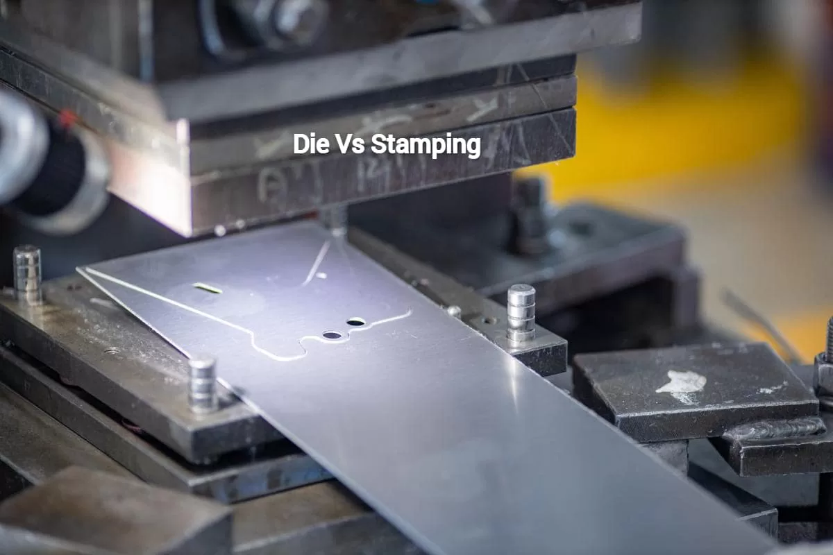
Custom Sheet Metal Punch Secrets: From Design to Die Maintenance
What Makes Custom Sheet Metal Punching Different
Ever watched a hole punch slice through paper? Now imagine that same concept scaled up dramatically—with hardened steel tools, thousands of pounds of force, and precision measured in thousandths of an inch. That's the world of custom sheet metal punch operations, where raw metal transforms into precisely shaped components for everything from automotive chassis to aerospace panels.
Whether you're an engineer specifying parts, a fabrication shop owner exploring new capabilities, or simply curious about how those perfectly uniform holes appear in metal products, understanding the fundamentals of metal punching opens the door to smarter manufacturing decisions.
The Mechanics Behind Metal Punching Operations
At its core, metal punching is elegantly simple. A hardened punch tool—typically made from tool steel or tungsten carbide—descends with significant force into a sheet of metal positioned above a matching die cavity. As the punch pushes through the material, it shears the metal cleanly, forcing a precisely shaped slug into the die opening below.
The punch and die relationship is the foundation of all metal punching operations: the punch acts as the male component that applies downward force, while the die serves as the female component that supports the material and defines the final hole or shape geometry.
Think of it like a cookie cutter meeting dough—except you're working with materials that demand extreme precision. The clearance between punch and die, the tool materials, and the force applied all determine whether you get a clean cut or a ragged edge. Every die punch set must be engineered to work in perfect harmony, with tolerances often measured in fractions of a millimeter.
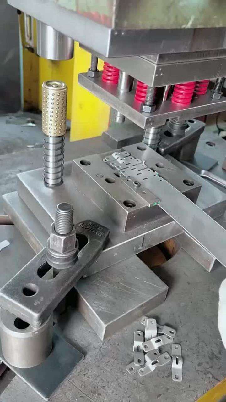
The process happens remarkably fast. Modern punch presses can cycle hundreds of times per minute, creating consistent holes with each stroke. This speed and repeatability make metal punching ideal for high-volume production runs where consistency matters.
When Standard Tooling Falls Short
Walk into any metalworking supply shop, and you'll find racks of standard punches—round holes in common diameters, perhaps some basic squares and rectangles. These off-the-shelf options work perfectly for generic applications where standard fastener holes or conventional shapes meet project requirements.
But manufacturing rarely stays generic for long. What happens when you need:
- A hole pattern matching a proprietary mounting configuration
- Custom shapes that align with brand-specific design elements
- Unusual dimensions that fall between standard sizing
- Specialized profiles for unique airflow or drainage requirements
This is where a custom sheet metal punch becomes essential. Unlike a personalised hole punch you might use for crafts, industrial custom tooling requires precision engineering. Custom metal punching allows you to specify exactly the hole size, pattern, and configuration your application demands—no compromises, no workarounds.
Consider architectural perforated panels requiring decorative patterns, or automotive components needing holes positioned for proprietary bracket systems. Standard tooling simply cannot accommodate these specialized requirements. A custom hole punch solution, engineered specifically for your application, ensures every part meets exact specifications while maintaining the production efficiency that makes punching cost-effective.
The investment in custom tooling pays dividends when you're producing hundreds or thousands of identical parts. Rather than forcing designs to accommodate available tooling, manufacturers can optimize their products and let the tooling follow the engineering requirements.
Punch Styles and Shape Configurations Explained
Now that you understand why custom tooling matters, let's explore the actual tools making these precision cuts happen. Selecting the right punch shape isn't just about matching hole geometry—it directly impacts how material flows during cutting, the quality of your finished edges, and ultimately, whether your parts perform as designed.
Think of punch selection like choosing the right drill bit. You wouldn't use a spade bit for precision cabinet hardware, and similarly, grabbing the wrong punch style leads to poor results, excessive wear, and frustrated operators. Understanding what each punch type does best helps you match tooling to application requirements from the start.
Round, Square, and Oblong Punch Applications
Round punches remain the workhorses of sheet metal fabrication. They're used extensively for fastener holes, ventilation openings, and wire routing passages. Because the cutting force distributes evenly around the circular perimeter, round punch press dies typically experience the longest service life and produce consistently clean edges.
When your application calls for structural connections or rectangular openings, a square metal punch tool or rectangular punch becomes essential. These shapes appear frequently in:
- Electrical enclosure cutouts for mounting components
- Structural bracket connections requiring square bolt patterns
- Slot openings for adjustable mounting positions
- HVAC ductwork connections and access panels
One important consideration with square and rectangular punches—corners create stress concentration points during cutting. Sharp corners experience significantly higher wear than rounded profiles, which is why many manufacturers specify custom radius punches that blend the structural benefits of rectangular shapes with the durability advantages of rounded corners.
Oblong punches handle slotted connections brilliantly. When parts need adjustment room during assembly, or when thermal expansion requires elongated mounting holes, oblong tooling delivers precisely shaped slots in a single stroke. This beats drilling round holes and then machining them into slots—saving both time and tooling costs.
Custom Profile Punches for Specialized Manufacturing
Sometimes standard shapes simply won't work. That's where custom profile punches enter the picture. These specialized tools are engineered from scratch to match your exact geometry requirements, whether that's a company logo, a complex functional profile, or an intricate pattern for decorative applications.
Special profile punches handle operations that standard tooling cannot address—lancing, notching, slots, and complex shapes that standard punch profiles cannot meet. The initial tooling investment runs higher than off-the-shelf options, but for production runs exceeding a few hundred parts, the per-piece efficiency gains quickly offset upfront costs.
Each die punch design affects how material behaves during the cutting stroke. Round profiles allow material to flow uniformly away from the cut zone. Complex profiles create uneven stress distributions that require careful attention to punch-to-die clearance and material support. When working with thinner materials especially, improper profile design leads to distortion around the punch site.
Interestingly, some principles from custom paper punch design translate to industrial applications—particularly regarding how complex shapes affect material behavior during cutting. However, industrial metal punching demands far tighter tolerances and more robust tool materials than any craft application could require.
| Shape | Common Applications | Material Thickness Range | Best Use Cases |
|---|---|---|---|
| Round | Fastener holes, ventilation, wire routing | 0.5mm - 12mm (material dependent) | High-volume production, standard fastener patterns |
| Square/Rectangular | Electrical cutouts, structural connections | 0.5mm - 10mm | Enclosure manufacturing, bracket mounting |
| Oblong/Slot | Adjustable mounting, thermal expansion slots | 0.5mm - 8mm | Assembly applications requiring positioning flexibility |
| Custom Profile | Logos, decorative patterns, functional shapes | 0.3mm - 6mm (complexity dependent) | Branding applications, specialized component requirements |
Punch selection directly impacts production efficiency and part quality. Choosing the appropriate style from the beginning eliminates rework, reduces scrap rates, and extends tooling life. As you evaluate your next project, consider not just what shape you need, but how that geometry will affect your entire production process—from initial setup through final part inspection.
Of course, even perfectly selected punch geometry won't help if you're working with the wrong material. Understanding how different metals respond to punching operations is equally critical for achieving quality results.
Material Selection for Optimal Punching Results
Here's a scenario that plays out in fabrication shops more often than anyone likes to admit: a perfectly designed custom punch meets its first production run, only to deliver ragged edges, excessive burrs, or worse—premature tool failure. The culprit? A mismatch between tooling specifications and material properties.
Selecting the right material for hole punching sheet metal operations isn't just a purchasing decision—it's a technical calculation that directly affects tool life, part quality, and production costs. Let's break down what you need to know about matching metals to your sheet metal punches.
Steel and Aluminum Punching Considerations
Not all metals respond equally when a hardened punch forces through them. Understanding these differences helps you select materials that cooperate with your tooling rather than fighting against it.
- Mild Steel (1008-1020): The most forgiving material for punching operations. Its relatively low tensile strength and moderate hardness mean standard metal punches and dies experience minimal wear. Mild steel punches cleanly across a wide range of thicknesses, making it ideal for high-volume production where tooling longevity matters.
- Stainless Steel (304, 316, 430 grades): Punching steel in stainless grades demands more tonnage and significantly impacts tool life. Higher tensile strength materials like stainless steel demand more tonnage and shorten punch life. Grades with higher chromium content prove especially abrasive, often requiring coated tooling (TiN, TiCN) to maintain acceptable wear rates.
- Aluminum Alloys (1100, 3003, 5052, 6061): Softer than steel, aluminum punches easily but presents its own challenges. The material's tendency to gall—adhering to punch surfaces during cutting—requires proper lubrication and sometimes specialized coatings. An aluminum punch set designed for high production volumes typically features polished surfaces that resist material buildup.
- Copper and Brass: These non-ferrous metals punch cleanly and cause relatively low tool wear. Copper's softness means careful attention to die clearance prevents distortion, while brass offers better dimensional stability during cutting. Both materials work well across standard thickness ranges without demanding exotic tooling materials.
Each material category brings specific requirements to steel punching operations. Matching press capacity to material strength is essential—maintaining at least 20% headroom below your machine's maximum tonnage prevents overloading and extends equipment life.
Material Thickness and Hardness Factors
Material hardness translates directly to tooling wear. Think of it this way: every time your punch shears through metal, microscopic particles abrade the cutting edge. Harder materials accelerate this process dramatically.
A general rule worth remembering: never punch a hole diameter smaller than the sheet thickness when working with high-strength alloys. Violating this ratio dramatically increases the risk of punch buckling and slug pulling—problems that damage tooling and compromise part quality.
Thickness considerations extend beyond simple capacity calculations. The relationship between material properties and punch-to-die clearance proves critical:
- Stainless steel: Requires approximately 8-10% of sheet thickness as clearance
- Mild steel: Typically uses 6-8% clearance for optimal results
- Aluminum: Can achieve clean cuts with just 4-5% clearance
- Copper and brass: Similar to aluminum, responding well to tighter clearances around 4-6%
When clearances aren't dialed in correctly, problems multiply. Improper material selection leads to premature tooling wear, burr formation, and dimensional inaccuracies that cascade through your entire production process. Sticking to correct clearance produces cleaner edges, less burr, and quieter operation.
Surface conditions matter too. Galvanized or prepainted sheets introduce coating layers that can gum up tooling or flake during punching. Testing small batches before committing to production runs helps identify whether you'll need adjusted clearances or additional lubrication.
When ordering custom tooling, communicating material specifications accurately prevents costly mismatches. Your punch manufacturer needs to know:
- Exact material grade and alloy composition
- Thickness range (including tolerances)
- Surface treatment or coating details
- Expected production volume
- Any special hardness or temper conditions
This information allows tooling engineers to specify appropriate punch materials, heat treatments, and coatings that match your application. Skipping this step often results in tooling that underperforms or fails prematurely—an expensive lesson that proper upfront communication easily avoids.
With material selection understood, the next critical consideration involves the technical specifications and tolerance standards that govern precision punching operations.
Technical Specifications and Tolerance Standards
You've selected the right punch style and matched your material—but here's where many fabrication projects go sideways. Without precise technical specifications governing your sheet metal punch and die relationship, even the best tooling and materials produce disappointing results.
Think of specifications as the rulebook that keeps every component of your punching operation in sync. Get the numbers wrong, and you'll battle burrs, distorted holes, and parts that don't fit their intended assemblies. Get them right, and your production runs smoothly with consistent, inspection-ready parts coming off the press.
Understanding Punch-to-Die Clearance Requirements
Clearance—the gap between your punch's outer edge and your die's inner edge—might seem like a minor detail. In reality, it's one of the most critical specifications affecting your entire operation. This small space determines how material shears, how cleanly edges form, and how long your sheet metal punches and dies will last before requiring maintenance.
When a punch descends into material positioned over a die, the metal doesn't simply "cut" like paper. Instead, it undergoes a controlled shearing process. The punch first compresses the material, then fractures it along carefully defined lines. Proper clearance ensures this fracture propagates cleanly from both the punch edge and the die edge, meeting in the middle to produce a smooth cut surface.
A correct clearance produces holes in which the upper one-third of the height is cylindrical and properly sheared, while the lower two-thirds are lightly conical and show controlled tear signs—this is the hallmark of a properly specified punching die operation.
What happens when clearance goes wrong? Two distinct failure modes emerge:
- Insufficient clearance: Creates a secondary shearing effect where fractures don't align properly. This generates excessive wear on the punch, increases required tonnage, and often produces rough, work-hardened edges that complicate downstream operations.
- Excessive clearance: Produces holes with an intermediate tear zone and significant loss of surface evenness. Parts exhibit larger burrs on the die side, and hole dimensions become inconsistent—problematic for precision assemblies.
Clearance specifications aren't one-size-fits-all. They vary based on material type, material thickness, and whether you're punching (keeping the material with the hole) or blanking (keeping the slug as your finished part). A punch & die set optimized for aluminum will perform poorly on stainless steel without clearance adjustments.
Tolerance Standards for Precision Applications
Beyond clearance, dimensional tolerances define how much variation is acceptable in your finished parts. For general fabrication work, tolerances might allow ±0.005" (0.127mm) or more. Precision applications—particularly in aerospace or medical devices—often demand ±0.001" (0.025mm) or tighter.
Hole size tolerances follow specific guidelines relative to material thickness. Industry best practices suggest:
- Minimum hole diameter: Equal to or greater than material thickness for ductile materials; 1.5× thickness for high-strength alloys
- Maximum hole size: Limited primarily by press tonnage capacity and die support structure
- Hole spacing: Maintain at least 2× material thickness between adjacent holes to prevent material distortion
- Edge distance: Keep holes at least 1.5× material thickness from sheet edges
These ratios matter because violating them creates stress concentrations that distort surrounding material. Punch too close to an edge, and that edge bows outward. Space holes too closely, and the web between them tears unpredictably.
For parts requiring bends after punching, additional considerations apply. Place holes approximately 2.5 times material thickness plus one bend radius away from bend lines to prevent distortion during forming operations. Ignoring this guideline results in oval holes and cosmetic defects that often require scrapping otherwise good parts.
The following table summarizes recommended clearance percentages for your sheet metal punch and die set based on material type and thickness ranges:
| Material | Thickness Range | Minimum/Blanking | Standard | Maximum |
|---|---|---|---|---|
| Aluminum, Copper, Brass | Up to 2mm | 8% | 10% | 12% |
| Aluminum, Copper, Brass | 2mm to 4mm | 10% | 12% | 15% |
| Aluminum, Copper, Brass | Over 4mm | 12% | 15% | 20% |
| Mild Steel (20-25 kg/mm²) | Up to 2.5mm | 15% | 18% | 20% |
| Mild Steel (30-40 kg/mm²) | 2.5mm to 5mm | 18% | 22% | 25% |
| Mild Steel (30-40 kg/mm²) | Over 5mm | 20% | 25% | 30% |
| Stainless Steel (60-80 kg/mm²) | Up to 1.5mm | 15% | 20% | 22% |
| Stainless Steel (60-80 kg/mm²) | 1.5mm to 3mm | 18% | 22% | 25% |
| Stainless Steel (60-80 kg/mm²) | Over 3mm | 20% | 25% | 28% |
Notice how harder materials require larger clearance percentages? This compensates for the increased shearing forces and helps prevent the secondary shearing that accelerates tool wear. When specifying sheet metal punch dies for a new application, start with standard clearance values and adjust based on edge quality observations during initial production runs.
Proper specifications prevent the quality issues that plague poorly planned operations. Burr formation, hole distortion, and premature tooling wear all trace back to specification errors—problems that cost far more to fix in production than to prevent through careful upfront engineering.
For tighter tolerances, expect closer fits between punch tools and dies, which increases tooling cost and accelerates wear during normal operation. The tradeoff is justified when part functionality demands it, but over-specifying tolerances on non-critical features wastes money without improving outcomes.
Understanding these technical specifications positions you to make informed decisions about tooling and production methods. But how does punching compare to other fabrication approaches when considering your specific application requirements?
Comparing Punching to Alternative Fabrication Methods
So you've got a stack of sheet metal that needs holes, cutouts, or complex profiles. Should you punch it, laser it, blast it with water, or hit it with plasma? This question drives countless manufacturing decisions—and getting the answer wrong means either overspending on low-volume work or bottlenecking high-production runs with the wrong technology.
Here's the reality: no single fabrication method wins every scenario. Each technology brings distinct advantages depending on your material, volume requirements, complexity, and budget constraints. Let's break down how custom sheet metal punching stacks up against the competition so you can match the right method to your specific application.
Punching Versus Laser and Plasma Cutting
When comparing metal punching tools to thermal cutting methods, the differences extend far beyond just "how the cut happens." Each approach affects your production timeline, part quality, and bottom line in distinct ways.
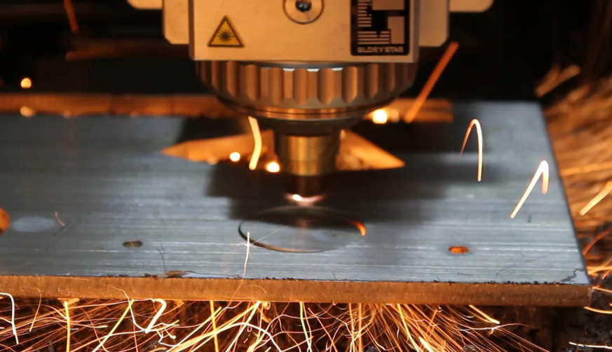
Laser Cutting: Precision Meets Flexibility
Laser cutting utilizes a focused, high-energy beam to melt or vaporize material with remarkable precision. According to industry comparisons, lasers excel when working with thin materials, offering incredibly fast cutting speeds and clean edges that often require minimal post-processing.
Where lasers really shine:
- Intricate designs: Complex geometries and tight curves that would require expensive custom punch tools cut easily with programmed laser paths
- Prototyping: No tooling investment means you can cut one-off parts immediately
- Thin gauge materials: Speed advantages become significant on materials under 3mm
However, highly reflective metals like copper and brass can challenge traditional CO2 lasers, though fiber laser technology continues improving capabilities with these materials. Edge quality typically rates excellent, making laser ideal for visible components or those requiring tight dimensional accuracy.
Plasma Cutting: Raw Power for Thick Stock
Plasma cutting uses ionized gas to slice through conductive metals quickly and affordably. It handles thicker materials than laser cutting at lower equipment costs, making it popular for structural steel fabrication.
The tradeoffs? Edge quality suffers compared to both laser and punching, often requiring secondary grinding or finishing. Heat-affected zones can alter material properties near cut edges—problematic for precision applications. For repetitive hole patterns in production environments, plasma simply cannot match the speed and consistency of punch metal sheet operations.
Waterjet Cutting: The Universal Cutter
Waterjet technology forces water mixed with abrasive garnet through a tiny orifice at extreme pressure, cutting virtually any material you throw at it. Waterjet excels at handling thicknesses up to 12 inches or more and leaves no heat-affected zone since it's a cold-cutting process.
Sounds perfect, right? Not so fast. Waterjet cutting tends to be slower than laser cutting, especially on thinner materials. Operating costs run higher due to consumables like garnet abrasive and specialized water treatment requirements. For high-volume sheet punching applications, waterjet simply cannot compete on per-part economics.
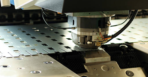
Where Punching Dominates
A sheetmetal hole punch operation—whether using standard tooling or custom configurations—delivers unmatched efficiency for specific scenarios:
- Repetitive features: Once tooled, creating identical holes takes fractions of a second per stroke
- High volumes: Per-part costs plummet as production quantities increase
- Consistent quality: Every punch produces identical results—no program drift or beam variations
- Multiple operations: Modern punch presses hold multiple tools, combining cutting, forming, and tapping in single setups
The edge quality from punch tools typically rates good to excellent, with minor deburring sometimes needed depending on material and clearance settings. Unlike thermal methods, punching creates no heat-affected zone, preserving material properties throughout the part.
Volume Considerations for Method Selection
Imagine you need 50 parts with complex cutouts. Now imagine you need 50,000 of those same parts. The optimal fabrication method changes dramatically between these scenarios—and understanding why helps you avoid costly mistakes.
Low-Volume Economics
For prototypes, short runs, or one-off custom parts, tooling investment becomes the critical factor. Laser and waterjet win here because they require zero part-specific tooling. You simply program the cutting path and start production immediately.
Custom punch tools require upfront investment—potentially hundreds or thousands of dollars depending on complexity. Spreading that cost across only a handful of parts makes per-piece economics unfavorable compared to no-tooling alternatives.
High-Volume Efficiency
Once production volumes climb into hundreds or thousands of parts, the equation flips entirely. For high-volume runs, the per-part operating cost of punching is often the lowest due to its speed and efficiency.
Consider this: a laser might cut a specific hole pattern in 30 seconds. A punch press creates that same pattern in under 2 seconds. Multiply that difference across 10,000 parts, and you're looking at days of saved machine time. Even with significant tooling investment, punching becomes dramatically more cost-effective at scale.
The Breakeven Question
Where exactly does punching become more economical than laser or waterjet? It depends on:
- Tooling complexity and cost
- Part cycle time on each technology
- Machine hourly rates in your region
- Secondary operation requirements
As a general guideline, simple hole patterns often break even around 200-500 parts. Complex custom tooling might require 1,000+ parts before per-piece costs favor punching. Your fabrication partner should be able to calculate specific crossover points based on your actual geometry and specifications.
The following comparison table summarizes how each fabrication method performs across key decision factors:
| Method | Speed | Cost at Low Volume | Cost at High Volume | Edge Quality | Best Applications |
|---|---|---|---|---|---|
| Punching | Very Fast (repetitive features) | Higher (tooling investment) | Lowest per-part | Good to Excellent | High-volume production, repetitive hole patterns, consistent shapes |
| Laser Cutting | Fast (thin materials) | Moderate (no tooling) | Moderate to High | Excellent | Intricate designs, prototypes, thin gauge precision work |
| Plasma Cutting | Fast (thick materials) | Low to Moderate | Moderate | Fair to Good | Thick structural steel, rough cutting, cost-sensitive projects |
| Waterjet Cutting | Slower | Moderate to High | Higher (consumables) | Good (sand-blasted finish) | Heat-sensitive materials, very thick stock, exotic alloys |
Hybrid Approaches
Smart manufacturers often combine technologies. A laser might cut complex outer profiles while a sheetmetal hole punch handles repetitive interior features. This hybrid approach captures the flexibility of laser cutting for geometry that would require expensive custom tooling while leveraging punching speed for standard features.
When evaluating your next project, consider not just which method cuts your material, but which approach optimizes your entire production workflow. The cheapest per-part cost means nothing if you're waiting weeks for parts that could ship in days.
With fabrication method selection clarified, understanding how different industries apply these technologies—and the specific standards they must meet—helps refine your approach for specialized applications.
Industry Applications from Automotive to Aerospace
Ever wonder what connects the chassis under your car, the structural panels inside an aircraft, and the decorative perforated metal bar adorning a modern building facade? They all rely on precision punching operations tailored to demanding industry-specific requirements. While the fundamental mechanics remain consistent, each sector brings unique challenges that separate capable manufacturers from truly specialized partners.
Understanding these industry-specific demands helps you communicate more effectively with suppliers, specify appropriate tolerances, and select partners equipped to meet your particular quality standards. Let's explore how custom punch applications differ across automotive, aerospace, and construction sectors.
Automotive and Chassis Component Requirements
The automotive industry consumes staggering quantities of punched metal components. A typical vehicle contains 300 to 500 stamped metal components, from battery terminals and sensor mounting brackets under the hood to seat mechanisms and door latch assemblies throughout the cabin.
Chassis components, suspension brackets, and structural reinforcements demand particularly precise hole patterns. These parts must align perfectly with mating components during high-speed assembly operations, leaving zero room for dimensional variation. A mounting hole positioned even slightly off-specification can prevent proper fastener installation—halting production lines that measure downtime in thousands of dollars per minute.
What makes automotive punching different from general fabrication? Consider these sector-specific requirements:
- Tolerance standards: Critical safety components require ±0.002 inches or tighter for seat belt anchors, airbag housings, and brake parts. Functional assemblies typically run ±0.005 to ±0.010 inches for engine mounts and suspension brackets.
- Material specifications: High-strength steel dominates crash-critical zones, while cold-rolled steel handles most brackets and structural components. Each material demands specific punch-to-die clearances and press tonnage calculations.
- Volume expectations: Production runs extending into hundreds of thousands or millions of parts require tooling designed for exceptional longevity. A custom punch that wears prematurely disrupts entire supply chains.
- Traceability requirements: Every lot of material and every tooling change must be documented to support potential recall investigations.
Perhaps most critically, automotive supply chain work demands IATF 16949 certification. This automotive-specific quality management standard builds on ISO 9001 with requirements for defect prevention, variation reduction, and rigorous supply chain management. Without it, you're not supplying major automakers.
For manufacturers seeking IATF 16949-certified custom punching capabilities, Shaoyi (Ningbo) Metal Technology exemplifies the comprehensive approach required. Their combination of rapid prototyping, automated mass production, and comprehensive DFM support addresses the full spectrum of automotive custom punch requirements—from initial design validation through high-volume production.
Aerospace and Construction Industry Standards
If automotive tolerances seem demanding, aerospace requirements push precision even further. When punching holes in materials destined for aircraft structures, tolerances tighten dramatically while material challenges intensify.
Consider the challenges faced by aerospace fabricators working with specialized alloys. One manufacturer successfully punches 0.100-inch diameter holes in 0.125-inch thick INCONEL—a nickel-based superalloy notorious for its hardness and abrasion resistance. This demands innovative approaches, including pre-cutting undersized holes with laser technology before using punches to shear the final diameter. The result? Holes meeting ±0.004 inch total tolerance with 45 percent land—specifications that seemed impossible with conventional approaches.
Aerospace metal punching services must address:
- Exotic materials: INCONEL, titanium alloys, and specialized aluminum grades resist punching operations, demanding premium tooling materials and sometimes hybrid laser-punch approaches.
- Tighter tolerances: While automotive might accept ±0.005 inches for functional parts, aerospace brackets often require ±0.002 inches or better on critical features.
- Stringent documentation: Every operation requires complete traceability, with first article inspections validating tooling before production begins.
- Secondary operation elimination: Combination punch/laser machines can hold ±0.002 inch diametrical tolerance on 0.100 inch holes, eliminating drilling operations that previously followed punching.
Construction and architectural applications present different challenges. Custom perforated metal panels for building facades, structural connection brackets, and ventilation systems require durability and aesthetic consistency rather than aerospace-level precision. However, these applications often involve larger panel sizes and decorative patterns that push the boundaries of standard punch press capabilities.
Architectural punching requirements typically include:
- Pattern consistency: Decorative perforations must maintain uniform spacing and appearance across large panel areas—any visible variation becomes an aesthetic defect.
- Corrosion resistance: Outdoor installations demand materials and coatings that withstand decades of weather exposure.
- Structural integrity: Perforated panels must maintain sufficient strength despite material removal, requiring careful engineering of perforation patterns.
- Custom profiles: Branded installations often require unique perforation shapes that create specific light patterns or corporate identities.
Whether you're sourcing American punch and die tooling for domestic production or partnering with international manufacturers, understanding these industry-specific requirements helps you communicate specifications accurately. The fabricator producing automotive chassis brackets operates under fundamentally different constraints than one creating architectural perforated panels—even when both use similar punch for metal operations.
With industry requirements clarified, the next critical consideration involves recognizing and preventing the quality issues that can derail even well-specified punching operations.
Troubleshooting Common Punching Quality Issues
You've specified the right tooling, selected appropriate materials, and dialed in your clearances—yet punched metal parts are still coming off the press with problems. Burrs catching on fingers during assembly. Holes that won't accept their intended fasteners. Edges that look more torn than sheared. Sound familiar?
Quality issues in custom sheet metal punching operations rarely appear without warning. They build gradually as tooling wears, clearances drift, and process parameters shift. The manufacturers who consistently produce inspection-ready parts aren't just lucky—they've developed systematic approaches to identifying problems early and correcting them before scrap rates climb. Let's walk through the most common quality issues you'll encounter with your piercing punch operations and how to address each one effectively.
Preventing Burr Formation and Edge Defects
Burrs—those unwanted projections and rough edges forming on punched parts—represent the single most common quality complaint in metal punching operations. Beyond cosmetic concerns, burrs create real problems: they pose safety hazards during handling, interfere with assembly operations, and often require costly secondary deburring processes.
Understanding what causes burrs helps you prevent them. According to industry research, several factors contribute to burr formation:
- Tool wear: As punches and dies wear, cutting edges become dull and rounded. Worn tools cause sheet metal to deform unevenly during punching rather than shearing cleanly.
- Incorrect clearance: When clearance between punch and die falls outside optimal ranges, the metal stretches and tears instead of fracturing cleanly along intended lines.
- Material properties: Softer, more ductile metals tend to form burrs more readily than harder materials. Material thickness also affects burr susceptibility.
- Punching speed: Operating too fast causes rapid deformation leading to burrs, while punching too slowly generates excessive heat that affects cut quality.
Your troubleshooting checklist for burr prevention should include:
- Inspect punch cutting edges for dullness, rounding, or visible wear marks
- Check die edges for chipping, cracking, or shiny spots indicating excessive friction
- Verify clearance settings match material type and thickness specifications
- Measure burr height on sample parts—establish acceptable limits and reject parts exceeding them
- Confirm punching speed falls within manufacturer recommendations for your metal die punch configuration
- Apply appropriate lubrication to reduce friction and heat buildup
When burrs appear despite proper setup, corrective actions include:
- Sharpen or replace tooling: Dull edges are the primary burr cause. Regular cleaning, lubrication, and inspection can reduce tooling wear and maintain up to 95% of original precision.
- Adjust clearance settings: Conduct test runs with different clearances, measuring burr height to identify optimal settings for your specific application.
- Switch materials if possible: When burrs prove unavoidable with a given material, consider harder alloys or different tempers that shear more cleanly.
- Optimize lubrication: Select lubricants matched to your material and apply them evenly to punch, die, and sheet metal surfaces.
Diagnosing Hole Distortion Problems
Hole distortion manifests in several ways: oval-shaped holes that should be round, dimensions outside tolerance, and tapered or bell-mouthed openings. Each symptom points to specific root causes in your punch and die tooling setup.
Distortion typically traces back to these issues:
- Excessive clearance: When the gap between punch and die grows too large, material stretches before fracturing. This produces holes with an intermediate tear zone and significant dimensional loss.
- Insufficient clearance: Too-tight clearance creates secondary shearing effects where fractures don't align properly, leading to rough edges and work-hardened hole surfaces.
- Misalignment: When punch and die aren't perfectly centered, cutting forces distribute unevenly, producing oval holes and accelerated wear on one side of the tooling.
- Inadequate stripper pressure: If the stripper doesn't hold material flat during punching, the sheet lifts and shifts, distorting hole geometry.
Diagnostic steps for hole distortion include:
- Measure hole dimensions at multiple points using calibrated pins or optical comparators
- Check for ovality by comparing measurements taken at 90-degree orientations
- Examine hole walls for even shear marks versus torn or stretched appearances
- Use dial indicators or laser alignment tools to verify punch-to-die concentricity
- Inspect stripper springs and confirm adequate pressure for material thickness
Addressing distortion requires systematic correction:
- Recalculate and reset clearance based on actual material properties and thickness
- Realign tooling using precision measurement equipment
- Replace worn guide components that allow lateral movement
- Increase stripper pressure or replace weakened springs
- For custom hole punchers, verify tooling matches original design specifications
Maintenance Practices That Prevent Quality Problems
The most cost-effective quality control happens before problems occur. Establishing systematic punch and die tooling maintenance routines prevents the gradual degradation that eventually produces defective parts.
Daily maintenance tasks should include:
- Wipe punches and dies with dry, lint-free cloths after each production run
- Remove debris from die cavities using compressed air
- Visually inspect cutting edges for obvious damage or wear indicators
- Check lubrication levels and reapply as needed
- Document any unusual sounds, increased force requirements, or quality variations
Weekly or monthly inspection routines expand to include:
- Remove tooling from the press for thorough cleaning and detailed inspection
- Examine cutting edges under magnification for micro-cracks or chipping
- Measure punch dimensions against original specifications to track wear progression
- Verify clearance settings and adjust as needed to compensate for wear
- Test sample parts and measure against tolerance requirements
Key wear indicators that signal maintenance needs:
- Increased burr height: Gradual burr growth indicates progressive edge dulling
- Rising tonnage requirements: Worn tooling demands more force to complete cuts
- Unusual noise during operation: Changes in sound often precede visible quality problems
- Shiny spots on punch tips: These indicate friction and galling that accelerate wear
- Cracks or chips: Any visible damage requires immediate attention—continued operation risks catastrophic tooling failure
For operations using customized hole puncher configurations, maintaining detailed records of each tool's service history helps predict replacement timing. Track production counts against wear measurements to establish lifecycle expectations for your specific materials and volumes.
The investment in systematic inspection and maintenance pays dividends through extended tooling life, consistent part quality, and reduced scrap rates. Shops that treat maintenance as an afterthought invariably spend more on replacement tooling and quality-related rework than those maintaining disciplined prevention programs.
With quality control systems in place, you're ready to tackle the next challenge: navigating the custom punch design and ordering process to ensure your tooling specifications translate accurately into production-ready tools.
The Custom Punch Design and Ordering Process
You've identified the quality issues to avoid and understand what makes precision tooling perform. Now comes the practical challenge that trips up many first-time buyers: how exactly do you translate your manufacturing needs into a custom hole puncher that arrives ready for production?
The journey from "we need custom tooling" to "parts are shipping" involves more communication, specification work, and decision-making than most engineers anticipate. Get the process right, and you'll receive tooling that performs flawlessly from the first stroke. Rush through it, and you're looking at costly revisions, delayed timelines, and tooling that never quite meets expectations.
Specifying Dimensions and Requirements Accurately
Every successful custom punch project starts with clear, complete specifications. The information you provide directly determines whether your tooling arrives ready for production or requires frustrating back-and-forth corrections.
Before contacting punch and die manufacturers, gather these essential details:
- Hole geometry: Exact dimensions including any corner radii, draft angles, or special profile features. For complex shapes, provide CAD files in common formats (DXF, DWG, STEP).
- Material specifications: Include grade, thickness range, and any surface treatments (galvanized, painted, coated) your tooling must handle.
- Tolerance requirements: Specify dimensional tolerances for hole size, position, and edge quality. Tighter tolerances increase tooling cost—specify only what your application truly requires.
- Production volume expectations: Whether you're running 500 parts annually or 50,000 monthly dramatically affects tooling material selection and design approach.
- Press specifications: Provide your machine's tonnage rating, ram stroke, tooling system (Wilson, Mate, Trumpf, etc.), and mounting dimensions.
Measuring requirements accurately prevents the most common ordering mistakes. Use calibrated instruments appropriate to your tolerance requirements—micrometers and calipers for standard work, optical comparators or CMM equipment for precision applications. When measuring existing parts or holes you're trying to replicate, document whether you're measuring nominal dimensions or actual produced sizes.
For applications requiring a custom hole punch with your logo or branded perforation pattern, provide vector artwork at actual size. Bitmap images require conversion and may not reproduce your design accurately. Specify minimum feature sizes your design contains—very fine details may not translate to durable tooling, especially for high-volume production.
From Quote Request to Finished Tooling
Understanding the complete ordering process helps you plan realistic timelines and set appropriate expectations with your production team. Even before the prototype, the concept must be brought to life from a schematic drawing—using those specifications to develop dies is the first step in physical prototyping.
- Initial inquiry and specification submission: Contact potential suppliers with your complete specification package. Quality manufacturers respond with clarifying questions—a supplier who quotes immediately without understanding your application may not deliver appropriate tooling.
- Quote review and comparison: Evaluate quotes beyond just price. Consider lead times, included services (DFM review, prototyping), warranty terms, and supplier capability for your specific application. Manufacturers like Shaoyi offer 12-hour quote turnaround with comprehensive DFM support, streamlining this phase significantly.
- Design review and optimization: Before tooling production begins, experienced suppliers review your specifications for manufacturability. Assessing the entire scope of work is critical in tooling—it sets expectations for the integrity of the finished die and project management benchmarks. This collaborative step often identifies opportunities to improve tooling life, reduce cost, or enhance part quality.
- Prototyping (when applicable): For complex or high-value applications, prototype tooling validates your design before committing to production-grade tools. Rapid prototyping options—some manufacturers offer 5-day turnaround—let you test form, fit, and function before full investment.
- Production tooling manufacture: Once design approval is complete, actual tooling production begins. Lead times vary from 2-4 weeks for standard configurations to 6-8 weeks for complex custom die cut punch sets requiring special materials or treatments.
- First article inspection and approval: Quality manufacturers produce sample parts using your new tooling and provide dimensional reports. Review these carefully against your specifications before approving full production use.
- Delivery and installation: Receive tooling with complete documentation including setup parameters, recommended clearances, and maintenance schedules. First production runs should include careful monitoring to verify performance matches expectations.
DIY/In-House Versus Outsourcing: Making the Right Decision
Should you develop tooling capabilities internally or partner with specialized suppliers? This decision affects not just your immediate project but your long-term manufacturing flexibility.
Factors Favoring In-House Tooling Development
- High customization frequency: If you're constantly developing new punch configurations, internal capabilities reduce lead times and external dependencies.
- Proprietary designs: Some applications involve intellectual property you prefer not sharing with external suppliers.
- Existing infrastructure: Shops already equipped with tool room capabilities—surface grinders, EDM equipment, heat treating—can add customizable hole punch production with incremental investment.
- Rapid iteration needs: Development environments requiring frequent design changes benefit from immediate tooling modification capability.
Factors Favoring Outsourced Tooling
- Specialized expertise: Professional punch and die manufacturers bring decades of accumulated knowledge about materials, geometries, and failure modes that in-house programs rarely match.
- Capital efficiency: Toolmaking equipment represents significant investment. Unless you're producing substantial tooling volumes, outsourcing often proves more economical.
- Quality consistency: Experienced suppliers maintain rigorous quality systems, inspection equipment, and process controls that smaller operations struggle to replicate.
- Capacity flexibility: External partners can absorb volume spikes without requiring internal staffing or equipment expansion.
Most manufacturing operations find a hybrid approach works best. Maintain internal capability for simple modifications and emergency repairs while partnering with specialized suppliers for complex new tooling development. This combination provides flexibility without the full burden of comprehensive in-house capabilities.
Tooling requires the right mindset—it's not just about taking customer specs and cutting the right die. It's about ensuring that the variables match up to the application expectations. Whether you're developing tooling internally or partnering with external experts, this principle guides every successful custom punch project.
With your tooling ordered and delivered, the final consideration involves protecting that investment through proper maintenance and lifecycle management.
Maintenance and Lifespan Considerations for Custom Tooling
Your custom tooling has arrived, first parts look perfect, and production is humming along. But here's the question that separates shops running lean operations from those constantly battling quality issues and unexpected downtime: how long will your tooling punches actually last, and what determines whether you get 50,000 punches or 500,000 from that investment?
The answer isn't a single number—it's a complex equation involving material hardness, production volume, maintenance discipline, and knowing when sharpening stops making sense. Understanding these factors transforms tooling from a mysterious expense into a predictable, manageable cost center.
Extending Tooling Life Through Proper Maintenance
Think of your metal punch and die set like a precision instrument. Neglect it, and performance degrades rapidly. Maintain it properly, and you'll extract maximum value from every dollar invested in custom tooling.
According to industry data, tooling lifespan varies dramatically based on application:
- Light-duty applications (thin plastics, aluminum): 100,000 to 500,000 punches with proper maintenance
- Medium-duty applications (mild steel, moderate thickness): 50,000 to 200,000 punches
- Heavy-duty applications (stainless steel, high-strength alloys): 10,000 to 50,000 punches
Those ranges span 5x or more—and the difference between hitting the low end versus the high end comes down almost entirely to maintenance practices.
Daily Maintenance Essentials
Consistent daily habits prevent the gradual degradation that eventually causes quality failures:
- Clean tooling after each production run using lint-free cloths—debris left on cutting edges accelerates wear
- Apply appropriate lubricant before storage; this reduces friction during subsequent operations and prevents corrosion
- Visually inspect cutting edges for chips, cracks, or unusual wear patterns
- Document production counts to track cumulative usage against expected lifespan
- Store tooling in protective cases or racks that prevent edge contact with other tools
Scheduled Inspection Routines
Beyond daily habits, establish regular deep-inspection intervals:
- Weekly: Remove tooling from the press for thorough cleaning and magnified edge inspection
- Monthly: Measure punch dimensions against original specifications to quantify wear progression
- Per 10,000-25,000 strokes: Conduct formal evaluation including edge sharpness testing and clearance verification
- Quarterly: Review maintenance logs to identify patterns suggesting process adjustments
Proper lubrication deserves special attention. Lubrication helps reduce friction between the die and punching material, which reduces heat generation and wear. Using lubricants specifically designed for punching operations—not generic machine oils—significantly extends tooling life, particularly when working with harder materials.
Storage conditions matter more than many shops realize. Ironworker dies and scotchman ironworker punch and die sets sitting in humid environments develop surface corrosion that damages cutting edges. Climate-controlled storage or vapor corrosion inhibitor packaging protects your investment during idle periods.
When to Repair Versus Replace Custom Tooling
Eventually, every punch dulls and every die wears. The critical decision becomes whether to sharpen, repair, or replace—and making that call correctly determines your true tooling economics.
Signs Indicating Maintenance Is Needed
- Burr height increasing beyond acceptable limits
- Press tonnage requirements climbing for identical operations
- Visible wear marks, rounded edges, or shiny spots on punch tips
- Unusual sounds during punching cycles
- Dimensional drift in punched features
Sharpening: The First Line of Defense
Professional resharpening restores cutting edges at a fraction of replacement cost. For standard roper whitney punch and dies and similar tooling, multiple resharpening cycles are possible before dimensional changes affect part quality. Establish a sharpening schedule based on production counts rather than waiting for quality problems to force the issue.
Consider the economics: repairing a tool is typically 50-80% cheaper than buying new, while properly maintained and repaired tools can last much longer, delaying costly replacements. That's significant savings on premium custom tooling that may have cost thousands of dollars initially.
When Replacement Becomes the Better Choice
Repair stops making sense when:
- Dimensional wear exceeds what resharpening can correct
- Cracks or chips compromise structural integrity
- Cumulative sharpening has reduced punch length beyond adjustment range
- The cost of repair approaches 60-70% of replacement cost
- Tooling technology has improved significantly since original purchase
For specialized tooling like ch 70 punch dies used in specific applications, replacement may involve lead times that require planning ahead. Track wear progression so you can order replacement tooling before existing tools fail completely.
The Economics of Tooling Investment
Smart manufacturers calculate tooling cost per part rather than focusing solely on purchase price. Consider this example:
- Custom punch cost: $800
- Expected lifespan with maintenance: 200,000 punches
- Cost per punch: $0.004
Now imagine neglecting maintenance reduces that lifespan to 75,000 punches:
- Cost per punch: $0.0107
That's nearly triple the per-part tooling cost—plus the quality issues, scrap, and unplanned downtime that accompany premature tooling failure. The "savings" from skipping maintenance evaporate quickly when you run the real numbers.
Invest in quality tool steels for your punching dies. Although they may be more expensive upfront, they will save you money in the long run by lasting longer and reducing the frequency of die replacements. Premium materials like D2 or M2 tool steels offer exceptional wear resistance that justifies higher initial costs across extended production runs.
By treating your custom sheet metal punch tooling as a managed asset rather than a consumable expense, you'll extract maximum value from every tooling investment while maintaining the consistent quality your customers expect.
Frequently Asked Questions About Custom Sheet Metal Punching
1. How much does a custom punch and die set cost?
Custom punch and die set pricing varies significantly based on complexity, materials, and tolerances. Simple round punches may cost a few hundred dollars, while complex profile tooling can reach several thousand. The investment typically pays off quickly in high-volume production, where per-part costs drop dramatically compared to no-tooling alternatives like laser cutting. IATF 16949-certified manufacturers like Shaoyi offer 12-hour quote turnaround to help you evaluate costs before committing.
2. What is the difference between a punch and a die in sheet metal work?
The punch is the male component that descends with force into the sheet metal, while the die is the female component positioned below that supports the material and defines the final hole geometry. Together, they create the punch-and-die relationship that shears metal cleanly. The clearance between these components—typically 4-25% of material thickness depending on the metal type—determines edge quality, burr formation, and tooling longevity.
3. Can I get a custom metal punch made for my specific application?
Yes, custom punches can be manufactured to match virtually any geometry, from simple non-standard diameters to complex branded logos and functional profiles. Manufacturers require detailed specifications including exact dimensions, material grade and thickness, tolerance requirements, and production volume expectations. Leading suppliers offer DFM support and rapid prototyping—some with 5-day turnaround—to validate designs before committing to production tooling.
4. How long does custom punch tooling last before needing replacement?
Tooling lifespan ranges from 10,000 punches for heavy-duty stainless steel applications to over 500,000 punches for light-duty aluminum work. Proper maintenance dramatically extends life—regular cleaning, appropriate lubrication, and scheduled sharpening can push tooling toward the high end of these ranges. Premium tool steels like D2 or M2 cost more initially but deliver significantly better wear resistance for extended production runs.
5. What materials can be processed with custom sheet metal punching?
Custom punching handles a wide range of metals including mild steel, stainless steel (304, 316, 430 grades), aluminum alloys, copper, and brass. Each material requires specific punch-to-die clearances and may demand different tooling materials or coatings. Harder materials like stainless steel accelerate tool wear and require more press tonnage, while softer materials like aluminum may need polished punch surfaces to prevent galling.