 Small batches, high standards. Our rapid prototyping service makes validation faster and easier —

Custom Sheet Metal Fabrication: 9 Essential Points Before You Order
What Custom Sheet Metal Fabrication Actually Means
Imagine starting with a simple flat sheet of metal and transforming it into a precision component that fits perfectly into your product design. That's exactly what custom sheet metal fabrication delivers—a manufacturing process that converts raw metal sheets into functional parts built to your exact specifications.
From Flat Stock to Functional Parts
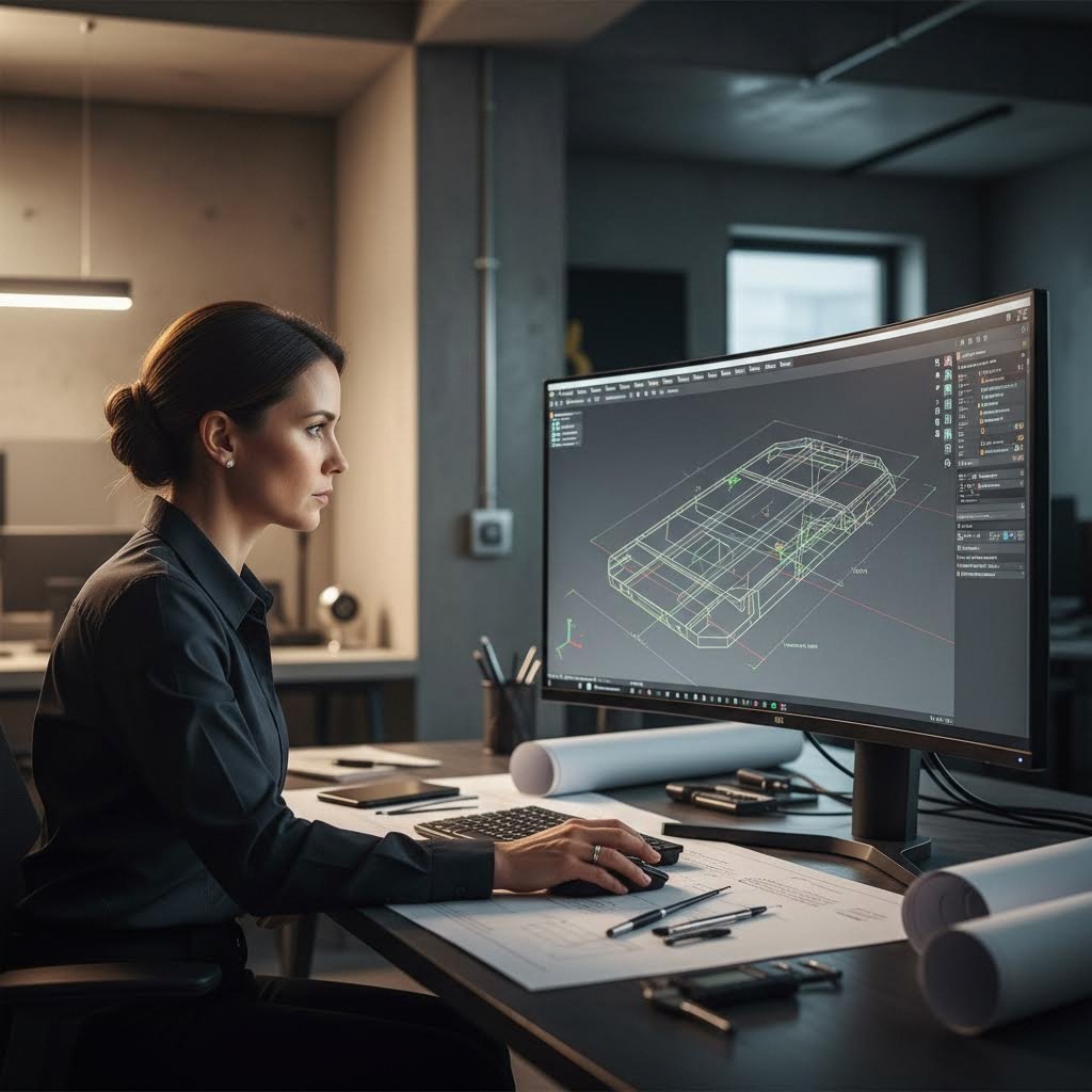
Custom sheet metal fabrication is the manufacturing of metal parts and products designed to meet a customer's exact requirements rather than relying on mass-produced standardized items. Metal fabricators work from CAD files, technical drawings, or detailed client descriptions to shape raw material into components like brackets, frames, fittings, enclosures, and structural elements.
Unlike purchasing standard sheet metal that comes in pre-defined sizes and thicknesses from online metals suppliers, the custom approach tailors every dimension, angle, and feature to your project's unique demands. This distinction matters significantly when you're developing products that require precision fitment or specialized functionality.
The Building Blocks of Metal Manufacturing
So what actually happens during this transformation? The metal fabrication process involves several core operations that work together to create finished components:
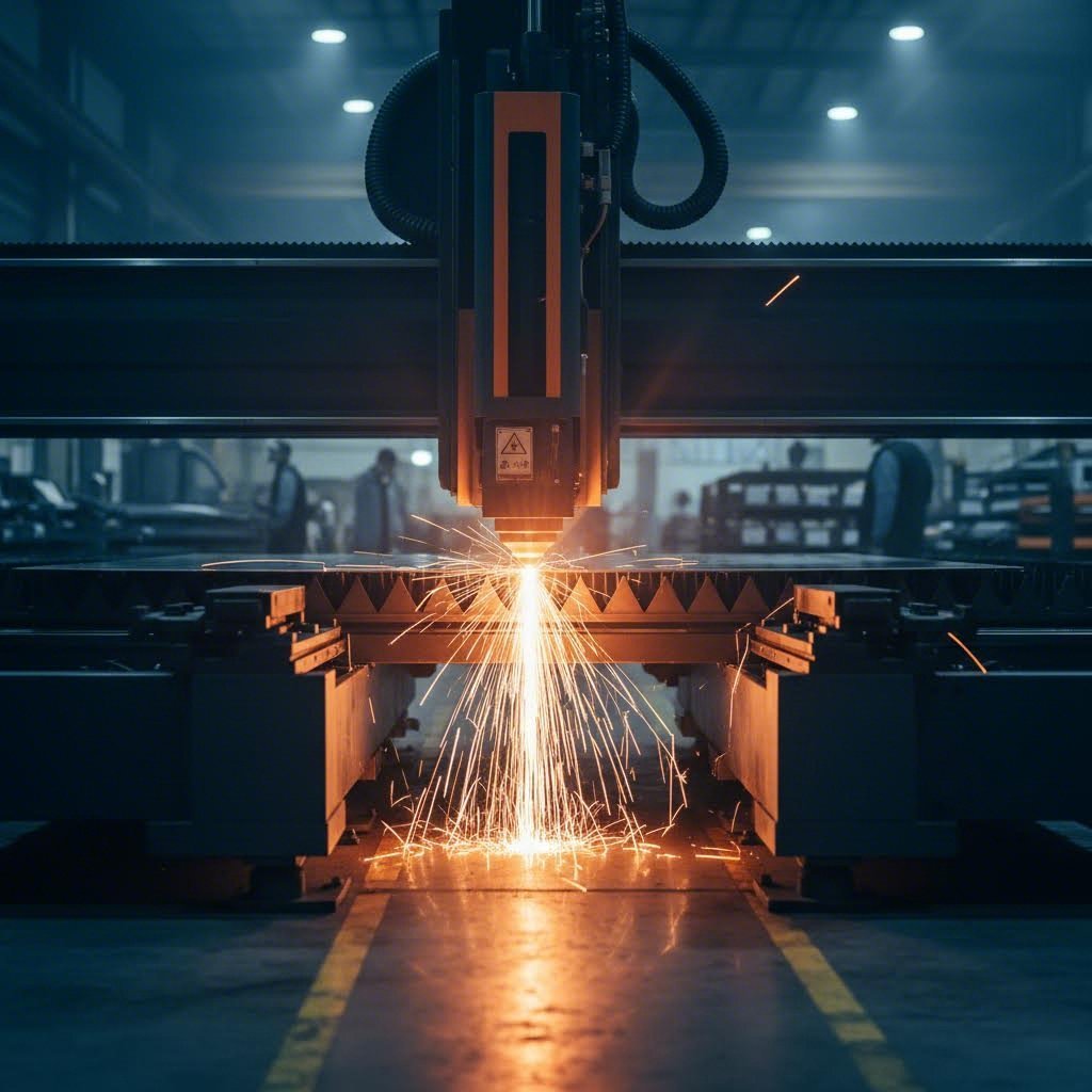
- Cutting: Advanced techniques like laser cutting, plasma cutting, or shearing slice sheet metal into precise shapes and dimensions
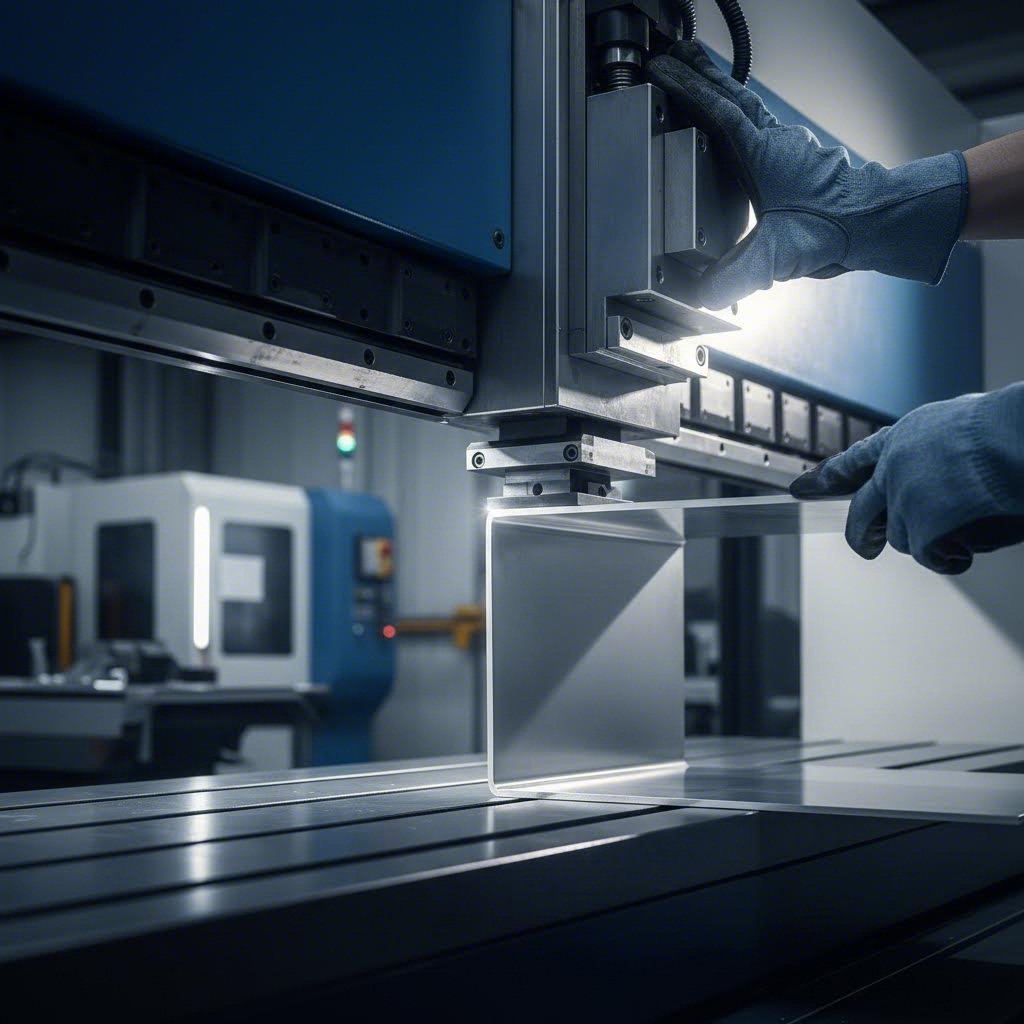
- Bending: Press brakes and forming equipment create angles, curves, and complex geometries from flat stock
- Forming: Specialized tools shape metal into three-dimensional configurations that flat cutting alone cannot achieve
- Joining: Welding methods including MIG, TIG, and spot welding fuse separate pieces into unified assemblies
Each operation requires careful sequencing and skilled execution. The sheet metal fabrication process typically begins with material selection based on your application's strength, weight, and corrosion resistance requirements. From there, computerized cutting tools achieve precise dimensions before bending and forming operations add depth and complexity.
Why does this matter for your projects? Industries like automotive, aerospace, electronics, and construction rely on custom metal fab solutions because standard off-the-shelf components simply cannot accommodate specialized designs or exacting tolerances. When you need a bracket that fits a unique mounting configuration or an enclosure with specific port placements, custom fabrication becomes essential rather than optional.
Core Fabrication Processes Explained
Understanding what happens to your metal after you submit a design file separates informed customers from those who simply hope for the best. Each fabrication process brings specific capabilities and limitations that directly impact your part's quality, cost, and lead time. Let's break down the core operations you'll encounter when working with custom sheet metal fabrication services.
Cutting Methods That Shape Your Design
Cutting is where your design meets reality. The method chosen determines edge quality, dimensional accuracy, and what materials you can work with. Three primary cutting technologies dominate modern fabrication shops: laser cutting, waterjet cutting, and CNC routing.
Laser Cutting uses a high-powered focused light beam to melt, burn, or vaporize material along a programmed path. Think of it as an extremely precise thermal scalpel. Modern fiber lasers ranging from 4kW to 12kW can cut upwards of 2,500 inches per minute, making this the fastest option for most applications. A laser cutter excels at intricate designs and tight tolerances, with most operations achieving accuracy within ±0.005 inches.
During laser cutting operations, some additional material burns away—this width is called the "kerf." While fabricators compensate for kerf automatically, you should know that extremely small features and intricate details can get lost in this process. Keep holes and cutouts at least 30% of material thickness or larger for best results.
One consideration with laser cutting is the heat-affected zone (HAZ)—the area adjacent to the cut where material properties may change slightly. However, modern high-speed lasers minimize this effect significantly, and for simple geometries, HAZ is virtually nonexistent.
Waterjet Cutting takes a completely different approach. Instead of heat, it uses an extremely high-pressure stream of water mixed with fine garnet abrasive to erode through material. The result? Zero heat-affected zone and an exceptionally smooth edge finish. This makes waterjet ideal for materials that don't respond well to thermal processes—composites like carbon fiber, G10, and phenolic materials that would crack or delaminate under laser heat.
CNC Routing employs a rotating cutter that physically removes material along programmed paths. If you understand what the CNC acronym refers to—Computer Numerical Control—you'll appreciate how and CNC routing achieves its precision through computer-directed tool movement. A cnc router cnc system excels with plastics, woods, and composites where surface finish quality matters more than cutting speed.
| Cutting Method | Precision Level | Material Thickness Range | Edge Quality | Best Applications |
|---|---|---|---|---|
| Laser Cutting | ±0.005" | Up to 0.5" (most metals) | Smooth with minor striations on thicker stock | Metals (steel, aluminum, copper, brass); intricate designs; high-volume production |
| Waterjet Cutting | ±0.009" | Up to 6"+ (varies by material) | Excellent; no burrs or dross | Composites; heat-sensitive materials; thick plates; aerospace components |
| CNC Routing | ±0.005" | Varies by material hardness | Superior surface finish | Plastics (ABS, HDPE); woods; composites requiring clean edges |
CNC Punching for High-Volume Features
When your design requires numerous holes, slots, or repetitive features, CNC punching becomes the efficiency champion. Unlike cutting operations that trace continuous paths, a CNC punch machine uses specialized tools to stamp out features with remarkable speed and consistency.
Here's how it works: a turret loaded with various punch and die sets rotates to position the correct tool, then strikes down through the sheet metal to create each feature. This process excels at producing round holes, square hole punches, slots, and complex patterns across large production runs. The automated nature eliminates human error while reducing setup time compared to manual methods.
CNC punching offers particular advantages for electrical enclosures, ventilation panels, and any component requiring consistent hole patterns. A single machine setup can produce hundreds or thousands of identical parts with tight tolerances. However, this method works best for thinner gauge materials and may leave small tabs or require secondary deburring operations.
For specialized cutting needs, some fabricators also utilize a die cut machine to produce specific shapes at high volumes, particularly for gaskets, shims, and thin-gauge applications where tooling costs can be justified by production quantity.
Bending and Forming Fundamentals
Cutting creates flat profiles—bending transforms them into three-dimensional components. Press brake forming is the workhorse operation here, using a punch and die set to create precise angles in sheet metal.
The relationship between bend radius and material thickness is fundamental to successful forming. The bend radius refers to the inside curve created when metal is bent—think of it as the tightness of the corner. This seemingly simple parameter actually determines whether your part will crack, wrinkle, or form cleanly.
The Golden Rule: An optimum bend radius approximately equals the material thickness. At this ratio, stress distributes evenly between inner and outer surfaces, springback is minimized, and angle consistency improves dramatically. Push the radius too small, and you risk cracking on the outer surface. Go too large, and wrinkling may occur on the inside.
Material properties significantly influence minimum bend radius requirements:
- Mild Steel (~60 KSI): Can typically bend to a radius equal to material thickness
- Stainless Steel (304/316, ~90 KSI): Requires larger radii due to higher yield strength and stronger springback
- Soft Aluminum (5052-H32, ~30 KSI): Conforms more readily, allowing tighter bend radii than equivalent steel thickness
Springback—the metal's tendency to partially return toward its original flat state after bending—is the hidden variable that separates amateur from professional results. Higher strength materials and larger radii produce more springback, requiring operators to "over-bend" slightly to achieve the target angle. Modern CNC press brakes can compensate automatically, but understanding this phenomenon helps you design parts that manufacture consistently.
For complex geometries beyond simple L-bends and U-channels, advanced forming techniques come into play. Step bending (bump bending) creates large-radius curves through dozens of incremental small bends. Hemming folds edges completely back on themselves for reinforcement or safety. Each technique requires specific tooling and expertise, adding cost but enabling designs that simple bending cannot achieve.
Knowing these process fundamentals helps you make smarter design decisions before submitting files for production. In the next section, we'll explore how material selection intersects with these fabrication capabilities to determine what's actually achievable for your project.
Material Selection Guide for Sheet Metal Projects
You've nailed down your design and understand the fabrication processes available. Now comes a decision that will define your part's performance for years: choosing the right material. This isn't about picking what's cheapest or most popular—it's about matching metal properties to your application's specific demands.
Matching Materials to Application Requirements
Every material brings trade-offs. Strength versus weight. Corrosion resistance versus cost. Formability versus durability. Understanding these relationships prevents costly mistakes and ensures your parts perform exactly as intended.
Aluminum Sheet Metal stands out when weight savings matter. At roughly one-third the density of steel, an aluminum sheet delivers dramatic weight reductions without sacrificing structural integrity for many applications. Beyond weight advantages, aluminum forms a protective oxide layer when exposed to air—this self-healing barrier provides excellent corrosion resistance without additional coatings.
Common aluminum alloys you'll encounter include:
- 5052: The workhorse for sheet metal applications—excellent formability, good corrosion resistance, and moderate strength
- 6061-T6: Heat-treated for higher strength, though less formable than 5052; ideal when structural demands increase
- 7075: Aerospace-grade strength approaching some steels, but significantly higher cost and reduced weldability
The trade-off? Aluminum is softer than steel, meaning it scratches more easily and doesn't handle abrasive wear as well. It also has a lower melting point, which matters for high-temperature applications but makes it excellent for heat sinks and thermal management components due to its high thermal conductivity.
Understanding Metal Properties for Your Project
Stainless Steel Sheet Metal commands attention when corrosion resistance and strength must coexist. But here's where many buyers stumble—not all stainless steels are created equal. The choice between 304 and 316 stainless steel grades can mean the difference between decades of reliable service and premature failure.
304 Stainless Steel (also known as A2 stainless) contains approximately 18% chromium and 8% nickel. This composition delivers excellent corrosion resistance for indoor and mildly corrosive environments. According to Ryerson's grade comparison, 304 is the most widely used stainless grade, appearing in kitchen equipment, architectural trim, fasteners, and general hardware. It welds easily, forms cleanly, and costs less than its marine-grade cousin.
316 Stainless Steel adds 2-3% molybdenum to the mix—and this addition changes everything for harsh environments. That molybdenum dramatically improves resistance to chlorides, acids, and saltwater exposure. If your parts will encounter coastal environments, chemical processing, pharmaceutical applications, or anything involving salt, 316 is worth the premium.
The practical difference? 316 typically costs 10-15% more than 304, but in chloride-rich environments, 304 can develop pitting corrosion that leads to early failure. Choosing the right grade upfront prevents expensive replacements later.
Mild Steel (Low Carbon Steel) remains the go-to choice for structural applications where corrosion isn't the primary concern. Grades like A36 and 1008 offer excellent strength, superior weldability, and the lowest material costs in the steel family. When your parts will be painted, powder coated, or used indoors, mild steel delivers the best value.
Galvanized Sheet Metal solves the corrosion problem for outdoor steel applications. The zinc coating sacrificially protects the underlying steel—even if scratched, the zinc corrodes before the base metal does. This makes galvanized material ideal for HVAC ductwork, outdoor enclosures, agricultural equipment, and any application facing weather exposure without the cost of stainless steel.
| Material | Tensile Strength | Corrosion Resistance | Formability | Weldability | Typical Applications |
|---|---|---|---|---|---|
| Aluminum 5052 | 33,000 PSI | Excellent (self-healing oxide) | Excellent | Good (requires AC TIG/MIG) | Enclosures, brackets, marine components, heat sinks |
| 304 Stainless | 73,000 PSI | Very Good (indoor/mild environments) | Good | Excellent | Kitchen equipment, architectural trim, hardware |
| 316 Stainless | 79,000 PSI | Excellent (chlorides, acids, marine) | Good | Excellent | Chemical processing, marine, pharmaceutical |
| Mild Steel (A36) | 58,000 PSI | Poor (requires coating) | Excellent | Excellent | Structural components, frames, brackets (painted) |
| Galvanized Steel | 42,000-55,000 PSI | Good (zinc sacrificial protection) | Good | Fair (requires special procedures) | HVAC, outdoor enclosures, agricultural equipment |
Understanding Gauge Thickness
Here's where sheet metal gets counterintuitive. Instead of specifying thickness directly in inches or millimeters, the industry often uses gauge numbers—and lower numbers mean thicker material. A gauge size chart becomes essential for translating between systems.
According to Xometry's gauge reference, this system developed from historical wire-drawing operations where thickness related to weight per square foot. The key point: gauge numbers aren't universal across materials. A 14-gauge steel sheet has different actual thickness than 14-gauge aluminum.
Common gauges you'll encounter in custom sheet metal fabrication:
- 22 Gauge: Approximately 0.030" (0.76mm) for steel—thin enough for light enclosures and decorative applications
- 18 Gauge: Approximately 0.048" (1.22mm) for steel—popular for electronics housings and medium-duty brackets
- 14 Gauge: Approximately 0.075" (1.90mm) for steel—substantial thickness for structural brackets and heavy-duty components
- 11 Gauge: Approximately 0.120" (3.05mm) for steel—approaching the upper limit of what's considered sheet metal versus plate
When specifying material thickness, stating the actual dimension in inches or millimeters eliminates ambiguity. If your fabricator's quote assumes one gauge standard while you intended another, the resulting parts won't meet specifications. Most fabrication services accept either format, but explicit measurements leave no room for interpretation errors.
Material selection directly impacts every downstream decision—from cutting method viability to achievable bend radii to finishing options. With your material choice informed by application requirements, you're ready to tackle the design rules that separate smooth production runs from costly redesign cycles.
Design for Manufacturability Best Practices
You've selected your material and understand the fabrication processes available. But here's where many projects go sideways: a perfectly reasonable-looking CAD model that simply cannot be manufactured—or can only be made at three times the expected cost. Design for manufacturability (DFM) bridges the gap between what you envision and what fabrication equipment can actually produce.
Design Rules That Save Time and Money
Think of DFM guidelines as the physics of sheet metal translated into practical design constraints. Every rule exists because metal behaves in predictable ways when cut, bent, and formed. Respecting these behaviors from the start eliminates the expensive back-and-forth of design revisions.
Minimum Bend Radius Requirements
Remember the relationship between bend radius and material thickness from earlier? Now let's put specific numbers to it. For ductile materials like mild steel and soft aluminum, your minimum inside bend radius should equal the material thickness. Working with 14 gauge steel thickness (approximately 0.075")? Plan for at least a 0.075" inside radius.
Harder materials demand larger radii. According to Five Flute's DFM guide, aluminum 6061-T6 requires a minimum bend radius of 4x material thickness to avoid cracking. If you're using 11 gauge steel thickness (approximately 0.120") in a hardened alloy, your minimum radius might need to reach 0.48" or more.
Why does this matter for your project? Specifying a tighter radius than the material allows results in one of two outcomes: cracked parts that fail inspection, or a manufacturer who flags the issue and delays your timeline while awaiting revised drawings.
Hole Placement Guidelines
Holes punched or cut too close to edges or bends will distort during forming operations. The metal stretches and compresses unevenly, pulling circular holes into ovals and shifting their positions. These distortions compound across multiple bends, potentially pushing critical mounting holes completely out of specification.
Follow these spacing rules consistently:
- Edge distance: Keep holes at least 1.5x material thickness from any edge
- Hole-to-hole spacing: Maintain 2x material thickness between adjacent holes
- Distance from bends: Position holes at least 2.5x thickness plus one bend radius away from bend lines
- Minimum hole diameter: Avoid holes smaller than material thickness—they won't punch cleanly
When consulting a drill size chart for secondary operations, remember that standard drill sizes don't always align with optimal punch tooling. Work with your fabricator to identify which hole diameters match their existing tooling, as custom punch tools add significant cost for low-volume orders.
Achievable Tolerances
Here's a reality check that saves both frustration and money: standard sheet metal processes economically achieve ±0.010" to ±0.030" tolerances. According to Consac's manufacturing guidelines, specifying tolerances tighter than ±0.005" drives up costs dramatically because it typically requires secondary machining operations.
Think about what your part actually needs. Mounting holes that align with standard hardware? ±0.015" works fine. Mating surfaces between welded assemblies? ±0.030" is often sufficient when proper fixturing is used. Reserve tight tolerances for the few critical dimensions that genuinely require them—your per-part cost will reflect the difference.
Avoiding Costly Redesign Cycles
The most expensive design changes happen after tooling is cut or production has started. Understanding common mistakes helps you catch them during the design phase when corrections cost nothing but a few minutes of CAD work.
Common Design Mistakes That Trigger Revisions:
- Insufficient bend relief: Without proper relief cuts at bend intersections, material tears and corners deform. Relief width should equal at least 1-1.5x material thickness
- Features too close to bends: Holes, slots, and tabs positioned within the deformation zone get pulled out of shape during forming
- Unrealistic tolerance callouts: Specifying ±0.002" on every dimension when ±0.020" would function identically—except at 5x the cost
- Ignoring grain direction: Cold-rolled sheet metal has a grain direction from manufacturing. Bends perpendicular to grain form more cleanly than parallel bends, especially in harder materials like 6061-T6 aluminum
- Forgetting kerf allowance: Laser and waterjet cutting removes material. A drill chart or cutting reference helps, but fabricators typically compensate automatically—just don't design features at the absolute limit of cutting capability
- Overlooking gauge sizes: Specifying non-standard thicknesses increases material cost and lead time. Stick to common gauges unless your application genuinely requires something unusual
How Proper DFM Reduces Lead Times
When your design file arrives at a fabrication shop, it goes through manufacturability review before quoting. Parts that follow DFM guidelines sail through this process—quotes come back quickly, production schedules get locked in, and your parts ship on time.
Parts with DFM issues trigger a different sequence. The fabricator flags problems, sends questions, waits for your engineering team's response, receives revised files, re-quotes, and finally schedules production. This cycle can add days or weeks to your timeline, and it often happens during the most time-critical project phases.
The relationship between design complexity and manufacturing cost follows a predictable pattern: each additional bend, each tight tolerance, each feature requiring special tooling adds cost. But complexity itself isn't the enemy—unnecessary complexity is. A part with twelve bends that follows DFM rules costs less to produce than a part with four bends that violates them.
Prevention genuinely costs less than correction. Investing time upfront to review your designs against these guidelines pays dividends in faster turnaround, lower per-part costs, and parts that work exactly as intended the first time they're assembled. With these design fundamentals in place, you're ready to understand what happens after you submit your files for production.
The Complete Fabrication Workflow
You've designed your part, selected your material, and applied DFM best practices. Now what? Understanding exactly what happens after you submit your design files transforms you from a passive customer into an informed partner who can anticipate timelines, avoid bottlenecks, and keep your project moving smoothly.
Your Design Journey from Concept to Component
The fabrication workflow isn't a black box—it's a predictable sequence of stages, each with specific inputs, outputs, and potential delay points. When you search for "metal fabrication near me" or "fabrication shops near me," you're looking for partners who execute this workflow reliably. Knowing what that workflow entails helps you evaluate whether a shop can actually deliver.
Here's the complete journey your design takes from submission to shipping:
- Design File Submission: You provide CAD files (STEP, IGES, or native formats) along with fully dimensioned 2D drawings. Include material specifications, finish requirements, and quantity needed. Missing information here pauses everything downstream.
- Engineering Review and DFM Analysis: The fabricator's engineering team examines your files for manufacturability issues—bend radii too tight, holes too close to edges, tolerances that require secondary operations. They'll flag concerns and request clarifications.
- Quoting: Based on material costs, machine time, labor requirements, and any secondary operations, you receive a detailed quote. Complex parts or specialty materials extend this phase.
- Quote Approval and Order Placement: Once you approve pricing and lead time, your order enters the production queue. This triggers material procurement if stock isn't already available.
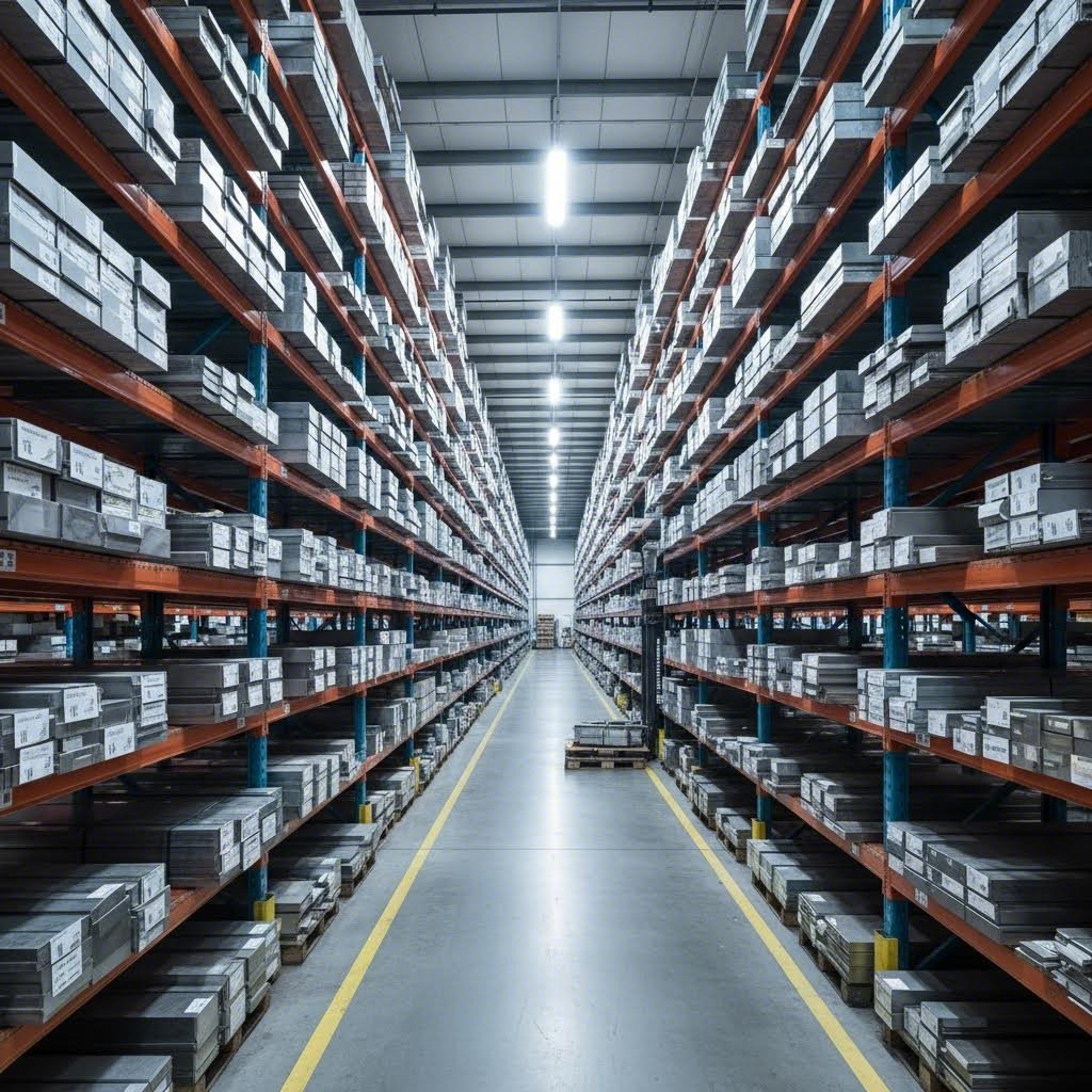
- Material Procurement: Standard materials like 304 stainless or 5052 aluminum often ship from service centers within days. Specialty alloys or unusual thicknesses can add weeks—this step frequently determines your overall lead time.
- Production Sequencing: Your parts move through cutting, punching, bending, and forming operations in a carefully planned order. Cutting always precedes bending; certain bends must happen before others to maintain access for tooling.
- Quality Inspection Checkpoints: First-article inspection verifies initial parts meet specifications before full production continues. In-process checks catch drift before it affects entire batches.
- Secondary Operations and Finishing: Hardware insertion, welding, powder coating, anodizing, or other treatments happen after primary fabrication. These often involve specialized third-party shops.
- Final Inspection and Packaging: Completed parts undergo final quality verification against your drawings. Protective packaging prevents damage during transit.
- Shipping: Parts leave the facility via your specified carrier and service level. Ground shipping adds days; air freight compresses timelines at higher cost.
What Happens After You Submit Your Design
File Format Requirements
Your lead time clock doesn't start until the fabricator has everything needed to begin work. According to Mingli Metal's lead time analysis, incomplete documentation causes the most common and avoidable delays in the entire process.
A complete submission package includes:
- 3D CAD files in universal formats (STEP or IGES preferred for compatibility)
- Fully dimensioned 2D drawings with tolerances, surface finish callouts, and critical dimension identification
- Material specification including grade, temper, and thickness
- Finish requirements with color codes if applicable
- Quantity and delivery timeline expectations
The Quoting Process
Several factors influence the price you'll see on your quote. Material cost is obvious, but machine time often dominates—complex geometries with many bends take longer than simple brackets. Setup costs get distributed across quantity, which is why per-unit pricing drops significantly at higher volumes. If you send cut send files to multiple metal fabricators near me for competitive quotes, you'll notice pricing varies based on each shop's equipment capabilities and current workload.
Why Production Sequencing Matters
Ever wonder why certain operations must happen in a specific order? Consider a simple enclosure with internal mounting tabs. If you bend the side walls first, the press brake tooling can't reach inside to form those tabs. The sequence must be: cut all features, form internal tabs, then bend the outer walls.
This sequencing logic scales to every complex part. Some bends create interference that blocks subsequent operations. Welding before final bending can distort parts. Hardware insertion sometimes must precede certain bends, other times must follow them. Experienced fabricators plan these sequences during DFM review—catching issues early prevents mid-production discoveries that scrap entire batches.
Quality Inspection Throughout Production
Quality isn't a final-stage checkbox—it's woven throughout the workflow. First-article inspection catches systematic errors before they multiply across hundreds of parts. Dimensional checks after critical operations verify that accumulated tolerances remain within specification. Final inspection confirms every requirement on your drawing has been met.
For complex assemblies requiring CMM (Coordinate Measuring Machine) verification, inspection adds measurable time to your schedule. Simple parts with visual checks move faster. Understanding this trade-off helps you specify appropriate inspection levels for your application's actual requirements.
Lead Time Reality Check
Your total lead time equals the sum of every stage, and bottlenecks in any single step delay the entire chain. Material procurement often dominates—standard stock might arrive in 3-5 days while specialty alloys take 4-6 weeks. Shop workload affects queue time. Secondary operations at outside facilities add transportation and separate scheduling delays.
Design choices you control directly impact this timeline. Simpler geometries process faster. Standard materials are readily available. Tolerances achievable without secondary machining eliminate extra steps. When speed matters more than cost, communicate that priority clearly—expedited options exist but require explicit trade-off discussions.
With a clear picture of the fabrication workflow, you're equipped to ask informed questions, set realistic expectations, and identify where your project might encounter delays before they happen. Next, we'll examine the cost factors that shape your quote and strategies for optimizing your budget without sacrificing quality.
Cost Factors and Pricing Considerations
You've navigated design requirements and workflow expectations—now let's talk money. Understanding what actually drives fabrication costs separates savvy buyers from those blindsided by quotes. The price you pay isn't just about raw material; it reflects processing difficulty, machine time, labor requirements, and every secondary operation your parts require.
Understanding What Drives Fabrication Costs
Material Selection: Beyond Raw Cost
When comparing alu sheets to steel plates, the sticker price per pound tells only part of the story. According to SendCutSend's cost analysis, material pricing between 5052 aluminum, HRPO mild steel, and 304 stainless steel is often closer than you'd expect when purchasing from high-volume suppliers. The real cost differences emerge in processing.
Harder materials like stainless steel wear cutting tools faster and require slower feed rates—both factors increase machine time. Thicker gauge steel plates demand more energy to cut and bend, adding to operational costs. Aluminum cuts and forms quickly but requires specialized welding procedures. Each material brings hidden processing implications that affect your final quote.
Quantity Effects on Per-Unit Pricing
Here's where understanding fabrication economics pays dividends: your first part always costs the most. Setup time—programming machines, loading material, configuring tooling—gets distributed across your entire order. Order one part, and you absorb 100% of setup costs. Order ten, and each part carries only 10%.
According to SendCutSend, a small zinc-plated G90 steel part costing $29 for a single unit drops to approximately $3 per part when ordering ten—an 86% discount driven almost entirely by setup cost distribution. Most materials see meaningful discounts starting with the second part and continuing through bulk orders.
Design Complexity and Machine Time
Complex designs translate directly to extended machine time. According to Zintilon's fabrication cost guide, intricate geometries requiring numerous cuts, bends, and welds demand more labor hours and specialized operator expertise. A part with twelve precision bends costs more than one with four simple angles—regardless of material cost.
Tight tolerances compound this effect. Specifying ±0.002" across your part when ±0.015" would function identically forces slower processing speeds, additional inspection steps, and potentially secondary machining operations. The labor component of steel fabrication costs rises in direct proportion to precision requirements.
| Cost Factor | Impact Level | Optimization Strategy |
|---|---|---|
| Material Selection | High | Choose standard alloys (5052 aluminum vs. 6061 when strength permits); match material to actual application requirements rather than over-specifying |
| Order Quantity | Very High | Batch similar parts together; order in quantities that maximize setup cost distribution; consider inventory costs vs. per-unit savings |
| Design Complexity | High | Minimize bend count; consolidate features where possible; use standard bend radii matching available tooling |
| Tolerance Requirements | Medium-High | Apply tight tolerances only to critical dimensions; specify ±0.015" or greater where functionality allows |
| Material Thickness | Medium | Use standard gauge sizes; avoid unnecessary thickness that adds weight and processing time |
| Secondary Operations | Medium-High | Evaluate necessity of each finish; consider pre-plated materials for corrosion resistance; batch finishing operations |
Smart Strategies for Budget Optimization
Secondary Operations: The Hidden Cost Multipliers
A raw aluminum part priced at $27 can jump to $43 with a powder coat finish—a 60% increase for surface treatment alone. According to industry cost data, finishing operations like powder coating and anodizing add substantial costs but often deliver long-term value through enhanced durability and appearance.
Steel fabricators typically offer multiple finishing paths, each with distinct cost implications:
- Powder coat: Excellent durability and color options; adds 40-80% to raw part cost depending on complexity
- Anodizing: For aluminum parts; Type II offers decorative finish and moderate corrosion protection; Type III (hardcoat) adds wear resistance at higher cost
- Hardware insertion: PEM fasteners, threaded inserts, and captive hardware add per-piece costs plus setup time
- Plating: Zinc, nickel, or chrome plating for steel parts requires external processing and minimum batch sizes
Consider whether finishes are genuinely necessary. Stainless steel's natural corrosion resistance eliminates coating needs for many applications. According to Zintilon, pre-plated materials like galvanized steel provide corrosion protection without separate finishing operations, though they may complicate welding if seams are required.
Actionable Tips for Cost Reduction Without Quality Sacrifice
- Stick to standard gauges: Non-standard thicknesses require custom material orders, extending lead times and increasing costs
- Specify appropriate tolerances: Reserve ±0.005" callouts for critical features; use ±0.015" to ±0.030" elsewhere
- Consolidate orders: Combining multiple part numbers into single production runs distributes setup costs more efficiently
- Simplify bend sequences: Fewer bends with standard radii matching existing tooling reduce machine time and operator complexity
- Evaluate material alternatives: If 5052 aluminum meets strength requirements, paying premium for 6061-T6 wastes budget
- Question every secondary operation: Does your indoor bracket genuinely need powder coating, or is raw finish acceptable?
- Consider natural corrosion resistance: Choosing stainless steel or aluminum eliminates protective coating costs entirely for appropriate applications
- Minimize part size: Larger parts consume more material and require more handling time—design only as large as function demands
Cost optimization in custom sheet metal fabrication isn't about cutting corners—it's about eliminating unnecessary expenses that don't contribute to your part's function. With these strategies in hand, the finishing options and secondary operations covered next will help you make informed decisions about the final steps that transform raw fabricated parts into production-ready components.
Finishing Options and Secondary Operations
Your fabricated parts emerge from cutting and bending operations as functional shapes—but they're not yet ready for service. The finishing stage transforms raw metal into components that resist corrosion, meet aesthetic requirements, and include the mounting features your assembly demands. Understanding these options helps you specify exactly what your application needs without overpaying for unnecessary treatments.
Surface Treatments That Protect and Enhance
Powder Coating: Durable Protection With Design Flexibility
Ever wonder why that bicycle frame or outdoor grill maintains its vibrant color through years of use? According to Fictiv's powder coating guide, powder coating creates a tough, high-quality finish that resists corrosion, chipping, and fading—making it superior to conventional liquid paints for demanding applications.
Here's how it works: dry powder particles receive an electrostatic charge and are sprayed onto grounded metal surfaces. The charged particles adhere uniformly, then the coated part enters a curing oven at 325–450°F for 10–30 minutes. Heat transforms the powder into a smooth, protective film that bonds permanently to the substrate.
Why choose powder coating over traditional paint? The benefits stack up quickly:
- Exceptional durability: Powder-coated surfaces resist scratches, chips, and chemicals while meeting strict standards like pencil hardness (ASTM D3363) and salt spray resistance (ASTM B117)
- Virtually unlimited color options: Custom finishes matching Pantone and RAL color standards are available, including matte, satin, gloss, metallic, and textured variations
- Environmental advantages: No solvents, minimal hazardous waste, and nearly 98% transfer efficiency thanks to reclaimable overspray
- Cost efficiency: Less product required compared to liquid paint, plus durability reduces long-term maintenance costs
The primary limitation? Powder coating requires heat curing, which means heat-sensitive materials and certain plastics cannot be processed this way. Additionally, coating thickness control between 2–6 mils requires experienced operators to avoid the "orange peel" texture that results from excessive application.
Anodizing: Engineered Protection for Aluminum
When your parts are aluminum and corrosion resistance matters, anodizing delivers protection that's literally built into the metal's surface. Unlike coatings that sit on top, anodized aluminum features an oxide layer that grows from the base material itself—making it impossible to chip or peel under normal conditions.
According to Hubs' anodizing comparison, understanding the difference between Type II and Type III anodizing determines whether your parts will perform as intended:
Type II Anodizing (Sulfuric Acid Anodizing) creates a thinner oxide layer ideal for decorative applications and moderate protection. It produces aesthetically pleasing finishes in a range of colors while improving corrosion resistance for indoor and mildly corrosive environments. You'll find Type II anodized aluminum in electronics enclosures, architectural trim, automotive accents, and consumer goods.
Type III Anodizing (Hardcoat Anodizing) uses lower temperatures and higher voltages to produce a significantly thicker, denser oxide layer. The result? Exceptional hardness and abrasion resistance suited for components facing harsh mechanical conditions. Type III also provides superior electrical insulation and greater thermal shock resistance—critical properties for aerospace landing gear, industrial machinery pistons, and high-performance automotive components.
The trade-offs are straightforward: Type III costs more due to extended processing time and delivers a darker, more industrial appearance compared to Type II's uniform aesthetic options. Dimensional changes are also more significant with Type III's thicker coating, potentially requiring design adjustments.
Adding Functionality Through Secondary Operations
Hardware Insertion Options
Raw sheet metal provides surfaces—but assemblies need attachment points. Hardware insertion operations add functional features that welding or machining would otherwise be needed to create.
PEM Fasteners are self-clinching components that press permanently into sheet metal, creating strong threaded holes without welding or secondary machining. Available as studs, nuts, and standoffs, they're ideal when you need reliable mounting points in thin materials that can't support tapped threads.
Threaded Inserts provide durable threads in materials too thin or soft for direct tapping. Heat-set inserts for plastics and press-fit inserts for metals create assembly points that withstand repeated fastener installation cycles.
Rivets offer permanent mechanical fastening when welding isn't practical or when joining dissimilar materials. Pop rivets work from one side, making them ideal for enclosed assemblies. Solid rivets require access to both sides but deliver maximum strength for structural applications.
Welding Considerations: MIG vs TIG Applications
When your assembly requires joined components, choosing the right welding method affects both quality and cost. According to Metal Works of High Point, understanding tig vs mig welding helps you specify the appropriate process for your application.
MIG Welding (Gas Metal Arc Welding) uses a continuously fed wire electrode and shielding gas. It's faster, easier to learn, and works well across various material thicknesses. When production speed matters and weld appearance is secondary to strength, MIG delivers efficiency. However, it produces more spatter and may require post-weld cleanup.
TIG Welding (Gas Tungsten Arc Welding) employs a non-consumable tungsten electrode with separate filler rod. The precision and control this method provides makes it ideal for:
- Thin materials prone to burn-through
- Visible welds requiring clean aesthetic appearance
- Aluminum welding where heat control is critical
- Dissimilar metal joining requiring precise heat input
The trade-off? TIG welding is slower and requires more operator skill, increasing labor costs. For structural applications where appearance matters less than strength and speed, MIG typically offers better value. For precision aluminum assemblies or visible joints, TIG's superior finish justifies the premium.
Common Finishing Options Summary
- Powder Coating: Durable colored finish for steel, aluminum, and other metals; excellent for outdoor and high-wear applications
- Anodizing (Type II): Decorative colored oxide layer for aluminum; moderate corrosion resistance with aesthetic flexibility
- Anodizing (Type III): Hardcoat oxide layer for aluminum; maximum wear and abrasion resistance for demanding environments
- Zinc Plating: Sacrificial corrosion protection for steel; lower cost than powder coating but limited color options
- Chromate Conversion: Chemical treatment providing corrosion resistance and paint adhesion for aluminum
- Brushed/Polished Finish: Mechanical surface treatment for stainless steel or aluminum; decorative without added coating
- Passivation: Chemical treatment enhancing stainless steel's natural corrosion resistance
Matching Finish Selection to End-Use Environment
Your finish choice should reflect where your parts will live and what they'll encounter. Indoor electronics enclosures might need only basic powder coating for aesthetics. Outdoor structural components facing salt spray demand either marine-grade anodizing or zinc-rich primers under powder coat. High-wear surfaces in industrial machinery benefit from Type III hardcoat anodizing's abrasion resistance.
Consider lifecycle costs alongside upfront finishing expenses. A slightly more expensive anodized finish that eliminates field corrosion issues often costs less over your product's lifespan than cheaper alternatives requiring replacement or refinishing. With finishing options clarified, you're equipped to evaluate fabrication partners who can deliver the complete package—from raw material through production-ready components.
Choosing the Right Fabrication Partner
You've mastered design principles, material selection, and finishing options. Now comes perhaps the most consequential decision in your custom sheet metal fabrication journey: selecting a manufacturing partner who can actually deliver what you need. The fabricator you choose affects not just part quality, but your project timeline, budget, and long-term production reliability.
Evaluating Fabrication Partners for Your Project
When searching for "sheet metal near me" or browsing potential metal sheet suppliers, you'll discover that most fabrication shops list similar equipment and capabilities. Laser cutters, press brakes, welding stations—the hardware looks interchangeable on paper. What actually separates exceptional partners from adequate ones? It comes down to five critical evaluation criteria.
Experience and Industry Knowledge
According to TMCO's fabrication partner guide, years in business translate into deeper material knowledge, refined processes, and the ability to anticipate challenges before they become costly problems. Experienced fabricators understand how different metals—aluminum, stainless steel, carbon steel, and specialty alloys—behave during cutting, forming, and welding.
Before committing, ask pointed questions:
- How long have they been fabricating complex metal sheets and assemblies?
- Do they have direct experience in your industry or with similar applications?
- Can they share case studies, sample parts, or customer references?
A fabricator serving automotive clients understands different tolerances than one focused on architectural corrugated metal panels. Industry-specific experience means fewer surprises during production.
In-House Capabilities and Technology
Not all shops offer the same depth of capability. Some only cut metal, outsourcing machining, finishing, or assembly to third parties. This fragmentation introduces delays, communication gaps, and quality inconsistencies. Full-service facilities with integrated capabilities provide tighter control over your entire production process.
Key capabilities to verify include:
- Laser cutting, plasma cutting, or waterjet cutting with appropriate capacity for your material thickness
- CNC machining and turning for secondary operations
- Precision forming with modern press brake equipment
- Certified welding capabilities (TIG/MIG) appropriate for your materials
- In-house finishing options or established relationships with quality finishers
- Assembly and testing support for complete sub-assemblies
Modern equipment with automation ensures repeatability, efficiency, and the ability to scale from prototype quantities to production volumes without quality degradation.
Engineering and Design Support
Successful fabrication begins before any metal cutter touches material. According to American Micro Industries, a reliable fabricator collaborates during the design phase, reviewing drawings, CAD files, tolerances, and functional requirements. This Design for Manufacturability support catches issues early—when corrections cost nothing—rather than during production when changes require expensive tooling modifications or scrapped material.
Evaluate whether potential partners provide:
- CAD/CAM support for file translation and optimization
- Prototype development and testing capabilities
- Engineering consultation on material selection and design alternatives
- Proactive recommendations that reduce cost without sacrificing function
For example, Shaoyi (Ningbo) Metal Technology exemplifies this approach with comprehensive DFM support integrated into their quoting process, helping automotive customers optimize designs before production commitment. Their 12-hour quote turnaround demonstrates the responsiveness that keeps projects moving.
Quality Certifications That Matter
Quality isn't just about appearance—it's about precision, performance, and reliability across every part you receive. The best fabricators follow documented quality systems and use advanced inspection tools to verify accuracy throughout production.
Understanding IATF 16949 Certification
For automotive applications, IATF 16949 certification represents the gold standard. According to DEKRA's certification overview, this international standard establishes uniform quality requirements specifically designed for automotive industry supply chains. It addresses critical concerns including:
- Traceability systems supporting regulatory compliance and recall management
- Safety-related parts and process controls
- Warranty management processes including "No Trouble Found" addressing
- Customer-specific requirements common across OEMs and Tier 1 suppliers
An IATF 16949-certified partner like Shaoyi has demonstrated systematic quality management verified through rigorous third-party auditing. For chassis, suspension, and structural components where failure isn't an option, this certification provides documented assurance that quality systems meet automotive industry expectations.
Quality Framework Components
Beyond certifications, evaluate the practical quality infrastructure:
- First-article inspection: Verification that initial production parts meet all specifications before full runs proceed
- In-process dimensional checks: Catching drift before it affects entire batches
- Weld integrity and structural testing: Ensuring joined components meet strength requirements
- CMM (Coordinate Measuring Machine) capability: Precision verification for tight-tolerance features
- Final inspection and performance validation: Confirming every requirement before shipping
Scalability: From Prototype to Production
Your ideal partner supports both current needs and future growth. Can they transition smoothly from 5-day rapid prototyping to automated mass production without quality degradation? Shaoyi's capabilities span this spectrum—from quick-turn prototypes for design validation through high-volume production for established programs—making them particularly valuable for automotive applications where development cycles compress while quality demands intensify.
Communication and Responsiveness
Transparent communication prevents costly surprises. According to industry guidance, evaluate how potential partners handle the relationship:
- Quote turnaround time—hours versus days signals capacity and prioritization
- Project manager accessibility and update frequency
- Proactive communication about potential issues versus reactive problem notification
- Technical support availability for design questions and material recommendations
- Responsiveness to your quality control requirements and documentation needs
A partner who delivers 12-hour quote turnaround demonstrates operational efficiency that typically extends throughout the production relationship. When schedule matters—and in automotive, it always does—responsiveness at the quoting stage predicts responsiveness during production.
Key Evaluation Criteria Summary
When comparing fabrication partners, weight these factors according to your project's priorities:
| Evaluation Criteria | What to Look For | Red Flags |
|---|---|---|
| Industry Experience | Documented history with similar applications; case studies; customer references | Vague responses about past projects; inability to provide samples |
| In-House Capabilities | Integrated cutting, forming, welding, finishing under one roof | Heavy reliance on outsourced operations; unclear process ownership |
| DFM Support | Proactive design review; engineering consultation; optimization recommendations | "Just send the files"—no design engagement before quoting |
| Quality Certifications | IATF 16949 for automotive; ISO 9001 for general manufacturing | No third-party certification; undocumented quality processes |
| Scalability | Rapid prototyping through mass production capability | Prototype-only focus; capacity constraints for volume orders |
| Communication | Fast quote turnaround; dedicated project management; proactive updates | Slow responses; difficulty reaching decision-makers; reactive-only communication |
The fabrication partner you select becomes an extension of your engineering team. Their capabilities, quality systems, and communication practices directly impact your product's success. Take time to verify claims, request samples, and evaluate responsiveness before committing—the investment in proper vetting pays dividends throughout your production relationship.
Getting Started With Your Custom Fabrication Project
You've absorbed nine essential points spanning materials, processes, design rules, workflows, costs, finishing options, and partner selection. Now it's time to transform that knowledge into action. Whether you're ordering a single prototype or planning production runs of thousands, the preparation steps remain remarkably consistent.
Putting Knowledge Into Action
Before contacting fabricators or uploading design files, run through this quick readiness checklist:
- Material specification locked: Have you matched your application's strength, corrosion, and weight requirements to a specific alloy and gauge?
- DFM principles applied: Are bend radii appropriate for your material? Are holes positioned correctly relative to edges and bends?
- Tolerance requirements justified: Have you reserved tight callouts only for genuinely critical dimensions?
- Complete file package ready: Do you have 3D CAD files, dimensioned 2D drawings, and finish specifications prepared?
- Quantity and timeline defined: Can you communicate volumes and delivery expectations clearly?
The most successful fabrication projects begin with thorough design preparation. Investing time upfront to verify manufacturability, specify appropriate tolerances, and prepare complete documentation eliminates costly revision cycles and keeps your timeline on track.
Applications Across Industries
Custom sheet metal fabrication supports an extraordinarily diverse range of applications—each with unique requirements that inform material and process decisions:
Automotive: From custom metal signs identifying assembly plants to structural chassis components, automotive applications demand IATF 16949-certified quality and tight tolerances. Brackets, mounting plates, heat shields, and enclosures must withstand vibration, temperature extremes, and years of service. For readers pursuing automotive projects, Shaoyi (Ningbo) Metal Technology offers 5-day rapid prototyping combined with comprehensive DFM support—an ideal starting point for validating designs before committing to production tooling.
Aerospace: Weight savings drive material selection toward aluminum alloys and titanium, while precision requirements push tolerances tighter than typical commercial applications. Every metal plate and structural component undergoes rigorous inspection and documentation.
Electronics Enclosures: EMI shielding, thermal management, and mounting provisions all influence design decisions. Steel plate construction provides excellent shielding, while aluminum offers weight advantages and superior heat dissipation.
Architectural Components: Durability meets aesthetics in facades, railings, and decorative elements. Material selection balances corrosion resistance with visual appeal—stainless steel for coastal environments, powder-coated aluminum for color flexibility.
Beyond metals, many fabrication shops also work with complementary materials. Polycarbonate sheets serve as transparent panels in enclosures and guards, while understanding how to cut plexiglass properly ensures clean edges for display applications. These capabilities often complement metal fabrication services when your assembly requires mixed-material construction.
Your Next Steps
Ready to move forward? Start by preparing your complete design package with material specifications and tolerance callouts. Request quotes from multiple fabricators, comparing not just price but also DFM feedback quality and communication responsiveness. For automotive applications requiring certified quality and rapid turnaround, explore Shaoyi's capabilities at their auto stamping parts resource—their 12-hour quote turnaround and integrated DFM support accelerate the journey from concept to production-ready components.
Custom sheet metal fabrication transforms your designs into functional reality. With the knowledge you've gained across these nine essential points, you're equipped to make informed decisions, communicate effectively with fabrication partners, and achieve results that meet your exact specifications.
Frequently Asked Questions About Custom Sheet Metal Fabrication
1. How much does custom sheet metal fabrication cost?
Custom sheet metal fabrication costs typically range from $4 to $48 per square foot, with average project costs between $418 and $3,018. Key pricing factors include material selection (aluminum vs. stainless steel), order quantity (setup costs distribute across larger batches, reducing per-unit pricing by up to 86%), design complexity, tolerance requirements, and secondary operations like powder coating or anodizing. Working with IATF 16949-certified manufacturers like Shaoyi can help optimize costs through comprehensive DFM support that identifies cost-saving design modifications before production begins.
2. Is sheet metal fabrication difficult?
Sheet metal fabrication involves complex challenges including intricate design execution, tight tolerance management, and proper material selection. Success requires understanding bend radius requirements relative to material thickness, proper hole placement guidelines, and achievable tolerances for each process. However, these challenges become manageable when partnering with experienced fabricators who provide DFM review services. Quality partners catch manufacturability issues during the design phase, preventing costly redesign cycles and production delays.
3. What is the difference between laser cutting and waterjet cutting for sheet metal?
Laser cutting uses focused light beams achieving ±0.005" precision at speeds up to 2,500 inches per minute, ideal for intricate metal designs up to 0.5" thickness. Waterjet cutting uses high-pressure water with abrasive to achieve ±0.009" precision with zero heat-affected zone, making it perfect for composites and heat-sensitive materials up to 6"+ thickness. Laser cutting excels in speed and precision for metals, while waterjet provides superior edge quality and material versatility without thermal distortion.
4. How do I choose between 304 and 316 stainless steel for my project?
Choose 304 stainless steel for indoor applications and mildly corrosive environments—it offers excellent corrosion resistance at lower cost, making it ideal for kitchen equipment, architectural trim, and general hardware. Select 316 stainless steel when parts face chlorides, acids, or saltwater exposure, as its added molybdenum dramatically improves resistance to pitting corrosion. While 316 costs 10-15% more, it prevents premature failure in coastal, chemical processing, or pharmaceutical applications.
5. What certifications should I look for in a sheet metal fabrication partner?
For automotive applications, IATF 16949 certification is essential—it establishes uniform quality requirements including traceability systems, safety-related process controls, and warranty management. ISO 9001 certification indicates documented quality management for general manufacturing. Beyond certifications, evaluate first-article inspection capabilities, in-process dimensional checks, CMM verification equipment, and weld integrity testing. Partners like Shaoyi combine IATF 16949 certification with rapid prototyping and 12-hour quote turnaround for comprehensive quality assurance.