 Small batches, high standards. Our rapid prototyping service makes validation faster and easier —

Custom Part Machining Costs Revealed: What Shops Won't Tell You
What Custom Part Machining Really Means for Your Project
Ever searched for a component only to find that nothing on the market quite fits your application? You're not alone. This is precisely where custom part machining becomes invaluable. But what exactly does this process involve, and when should you consider it over grabbing a standard part from a catalog?
Custom part machining is the process of creating components specifically designed and manufactured to meet unique specifications, using precision CNC equipment to transform raw materials into finished parts that standard off-the-shelf options simply cannot match.
Unlike mass-produced components with standardized dimensions, custom machined parts are tailored to your exact requirements - from geometry and tolerances to material selection and surface finish. Industries ranging from aerospace and automotive to medical devices rely heavily on this approach when precision and performance cannot be compromised.
From Blueprint to Finished Component
The journey of precision CNC machining begins long before metal meets cutting tool. Your engineering team creates a detailed CAD model specifying exact dimensions, tolerances, and material requirements. This blueprint guides every subsequent step. During prototyping, the design is tested and refined until it performs exactly as intended. Only then does full-scale production begin, with CNC machines executing programmed operations like milling, turning, and drilling with remarkable accuracy.
Why Standard Parts Fall Short
Off-the-shelf components offer convenience and lower upfront costs through mass production economics. However, they come with inherent limitations. When your application demands unique geometry, specific material properties, or tolerances tighter than what is delrin or other standard plastic components can achieve, standardized parts simply won't perform. Custom machine solutions solve compatibility issues with existing systems and enable innovative designs that give you a competitive edge.
The Custom Machining Difference
What sets machined parts apart from their off-the-shelf counterparts? The answer lies in three key advantages:
- Precision fit: Parts manufactured to your exact specifications, with tolerances as tight as 0.003-0.005 inches
- Material flexibility: Choose from metals like aluminum, steel, and titanium, or engineering plastics including nylon and Delrin
- Application optimization: Components designed specifically for your performance requirements
Throughout this article, you'll discover what actually drives machining costs, how to optimize your designs for manufacturability, and what shops often don't tell you about pricing. Whether you're sourcing a single prototype or planning a production run, understanding these fundamentals will help you make smarter decisions and potentially save thousands on your next project.
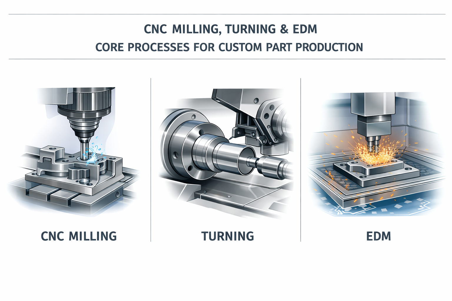
Core Machining Processes Behind Custom Parts
So you've decided custom machined components are the right path forward. But here's where it gets interesting - the specific process used to create your part dramatically affects cost, lead time, and achievable precision. Understanding these core methods helps you make smarter decisions before requesting quotes and gives you leverage when discussing options with machine shops.
Let's break down the primary CNC fabrication processes you'll encounter and when each makes the most sense for your project.
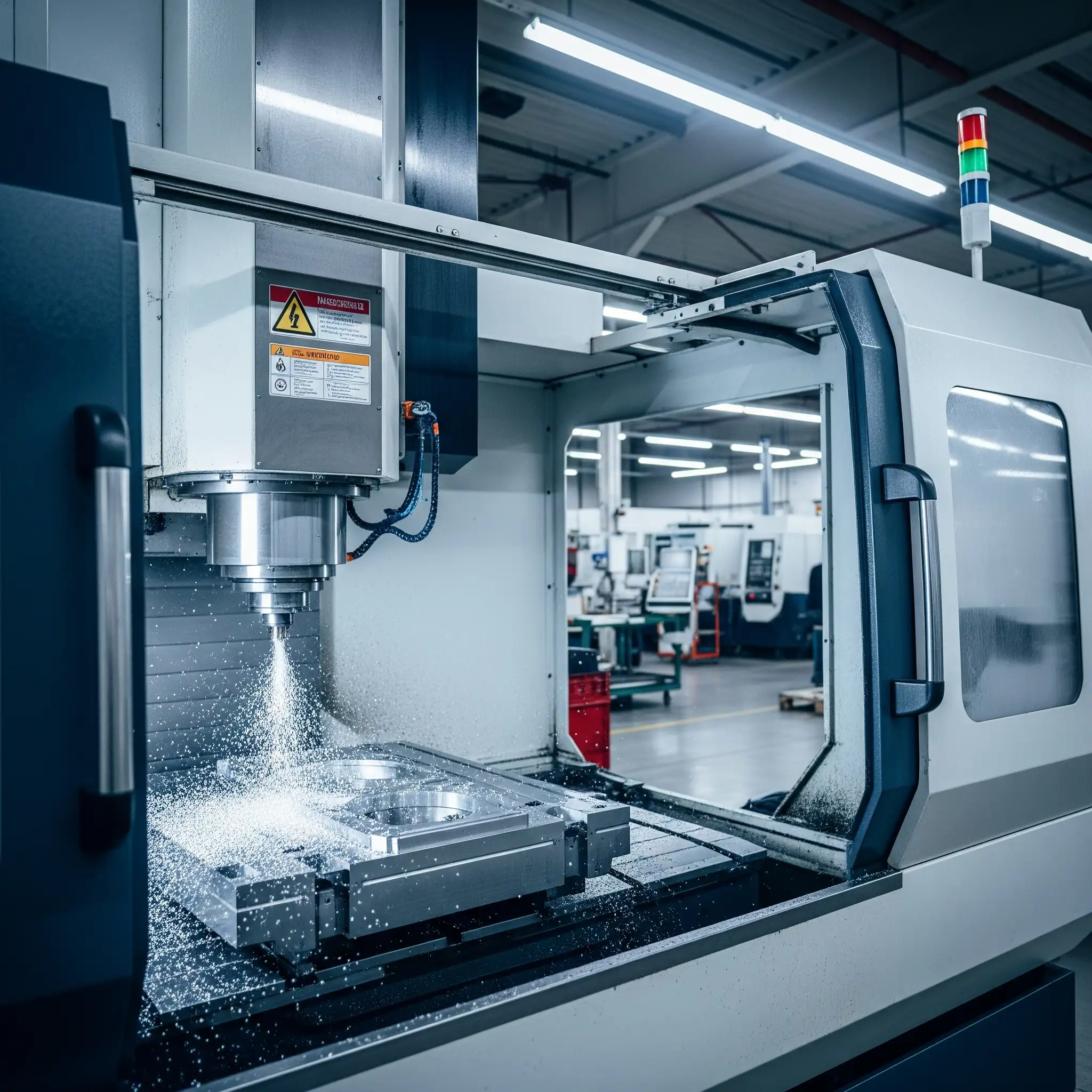
CNC Milling Explained
Imagine a rotating cutting tool moving across a stationary workpiece, carving away material layer by layer. That's CNC milling in action. This subtractive process excels at creating complex geometries, intricate contours, and detailed surface features that would be impossible with other methods.
When a CNC machine performs milling operations, it can move the cutting tool along multiple axes simultaneously. This versatility makes milling the go-to choice for:
- Flat surfaces and pockets: Creating recessed features, slots, and precisely flat faces
- Complex 3D contours: Sculpting curved surfaces and organic shapes
- Holes and threads: Drilling and tapping operations integrated into the same setup
- Text milling: Engraving part numbers, logos, or identification marks directly into components
The trade-off? CNC milling typically involves higher tooling and setup costs compared to simpler processes. For straightforward high-volume production of basic shapes, it may not be the most economical choice. However, when your design demands intricate details or you're working with tough materials like hardened steel or titanium, milling delivers unmatched capability.
When Turning Makes Sense
Here's a different approach: what if the workpiece rotates while a stationary cutting tool shapes its surface? That's CNC turning, and it's specifically engineered for cylindrical and symmetrical components.
Think shafts, bushings, tubes, bolts, and nozzles. Any part with rotational symmetry is a prime candidate for this process. CNC turning operations primarily work along two axes (X and Z), though advanced machines offer additional capabilities.
Why choose turning over milling for round parts? Speed and economics. According to manufacturing research, selecting the right CNC process can reduce manufacturing time by up to 30% while eliminating significant operational costs. For high-volume production of cylindrical components, turning simply can't be beat.
CNC turning also produces exceptionally smooth surface finishes on round parts because of its continuous cutting action. If your application requires tight tolerances on cylindrical features, this process delivers superior results compared to milling the same geometry.
Advanced Multi-Axis Capabilities
Standard 3-axis milling handles most applications, but complex parts sometimes demand more. That's where 4-axis and 5-axis CNC cutting capabilities come into play.
- 3-axis milling: Tool moves along X, Y, and Z axes - ideal for most flat and moderately contoured parts
- 4-axis milling: Adds rotation around one axis, enabling machining of features on multiple sides without repositioning
- 5-axis milling: Simultaneous movement along five axes, perfect for aerospace components, turbine blades, and complex medical implants
- Swiss machining: Specialized turning process for small, precision components like watch parts and medical instruments, offering exceptional accuracy on long, slender parts
Beyond traditional milling and turning, specialized processes handle unique requirements. Wire EDM (electrical discharge machining) uses electrical discharges to cut through conductive materials with extreme precision - tolerances as tight as 40 millionths of an inch. This technique excels with pre-hardened tool steels and materials that would destroy conventional cutting tools. The wire never actually touches the workpiece, meaning virtually zero mechanical stress or distortion.
However, wire EDM only works with conductive materials and operates more slowly than conventional CNC cuts, typically resulting in higher per-part costs. It's the right choice when precision trumps speed or when working with exceptionally hard materials.
| Process | Best For | Typical Tolerance | Relative Cost |
|---|---|---|---|
| 3-Axis Milling | Flat parts, pockets, basic contours | ±0.005" | Low-Medium |
| 5-Axis Milling | Complex geometries, undercuts | ±0.002" | High |
| CNC Turning | Cylindrical parts, shafts, bushings | ±0.003" | Low |
| Swiss Machining | Small precision parts, long slender components | ±0.0005" | Medium-High |
| Wire EDM | Hard materials, extreme precision, complex 2D profiles | ±0.0001" | High |
Choosing the right process isn't just about capability - it directly impacts your bottom line. A part designed for 5-axis milling when 3-axis would suffice means paying for machine time you don't need. Conversely, forcing a complex geometry onto a simpler process often requires multiple setups, actually increasing total cost.
With these foundational processes in mind, the next critical decision involves selecting the right material for your CNC milled components - a choice that affects everything from machinability to final part performance.
Material Selection Guide for Machined Components
Here's a question that trips up even experienced engineers: why do two seemingly similar parts cost dramatically different amounts to machine? The answer often lies in material selection. Choosing the right material isn't just about matching mechanical properties to your application - it directly affects machining time, tool wear, surface finish quality, and ultimately, your project budget.
Let's walk through the most commonly specified materials in custom part machining and explore when each makes sense for your specific needs.
Aluminum Alloys for Lightweight Strength
Aluminum dominates the custom machining world for good reason. It's lightweight, corrosion-resistant, and machines like a dream. But not all aluminum alloys perform equally, and understanding the differences can save you money while improving part performance.
6061 Aluminum is the workhorse of the industry. With a density of approximately 2.7 g/cm³ (nearly identical to pure aluminum), it offers excellent workability, corrosion resistance, and joinability. You'll find 6061 in everything from welded assemblies and electronics housings to marine fittings and automotive components. Its versatility makes it the default choice when you need a reliable, cost-effective aluminum option.
7075 Aluminum steps up when strength becomes critical. Often called "aircraft grade" aluminum, this alloy delivers one of the highest strength-to-weight ratios available. Its density of 2.81 g/cm³ is slightly higher due to zinc alloying elements, but that trade-off brings exceptional performance in high-stress applications. Aerospace components, defense equipment, and parts subjected to significant wear and tear benefit from 7075's superior mechanical properties.
The catch? 7075 doesn't weld or form as easily as 6061. If your design requires welding or complex bending operations, 6061 remains the smarter choice despite its lower strength ratings.
Steel Selection by Application
When aluminum can't handle the load, heat, or wear requirements, steel steps in. The challenge lies in selecting from dozens of available grades, each optimized for different performance characteristics.
- 1045 Carbon Steel: A medium-carbon option offering good strength and machinability at low cost - ideal for shafts, gears, and general mechanical components
- Stainless Steel (304, 316): Corrosion resistance for food processing, medical, and marine applications, though slower to machine than carbon steels
- Tool Steels (A2, D2, O1): Exceptional hardness and wear resistance for dies, punches, and cutting tools - often machined in annealed state, then heat-treated
Specialty metals fill specific niches. Titanium offers aerospace-grade strength-to-weight performance but costs significantly more to machine due to tool wear and slower cutting speeds. When you need to machine bronze or brass, you'll appreciate their excellent machinability ratings - CNC bronze components cut cleanly with minimal tool wear, making them economical choices for bushings, bearings, and decorative hardware. Bronze CNC operations also benefit from the material's natural lubricity in bearing applications.
Engineering Plastics and Their Trade-offs
Engineering plastics offer advantages that metals simply can't match: lighter weight, chemical resistance, electrical insulation, and often lower machining costs. However, each plastic brings distinct behaviors that affect both manufacturing and end-use performance.
Delrin (Acetal/POM) stands out for dimensional stability and machinability. This delrin plastic machines cleanly, leaving smooth surfaces with sharp edges straight off the tool. Its low moisture absorption means parts maintain tight tolerances even in humid environments - critical for precision assemblies, valve components, and pump bodies. Many shops consider it a "free-cutting" plastic because it forms clean chips and runs cool during machining.
Nylon for machining applications offers superior impact resistance and heat tolerance compared to Delrin. Glass-filled nylon grades can handle continuous temperatures around 120-130°C, making them suitable for under-hood automotive components and electrical housings. The trade-off? Nylon absorbs moisture from the air, which can change dimensions and strength over time. This hygroscopic behavior requires conditioning before machining and careful consideration in humid operating environments.
Polycarbonate (PC) delivers exceptional impact strength and optical clarity. When you need transparent components that can take a beating, polycarbonate PC outperforms most alternatives. Medical device housings, safety guards, and optical components frequently specify this material.
PTFE (Teflon) provides unmatched chemical resistance and the lowest coefficient of friction of any solid material. Seals, gaskets, and components exposed to aggressive chemicals benefit from PTFE's inertness, though its softness requires careful machining parameters.
| Material | Machinability | Typical Applications | Relative Cost | Key Properties |
|---|---|---|---|---|
| Aluminum 6061 | Excellent | Housings, brackets, frames | Low | Weldable, corrosion-resistant |
| Aluminum 7075 | Good | Aerospace, high-stress parts | Medium | High strength, fatigue-resistant |
| Stainless 304/316 | Moderate | Medical, food, marine | Medium-High | Corrosion-resistant |
| Bronze/Brass | Excellent | Bushings, bearings, fittings | Medium | Self-lubricating, decorative |
| Delrin (Acetal) | Excellent | Gears, valves, precision parts | Low-Medium | Dimensionally stable, low moisture |
| Nylon 6/6 | Good | Bearings, wear parts, housings | Low | Impact-resistant, heat-tolerant |
| Polycarbonate | Good | Guards, optical, medical | Medium | Clear, impact-resistant |
| PTFE | Moderate | Seals, gaskets, chemical handling | High | Chemical-resistant, low friction |
So when should material properties drive your decision versus cost? Consider this framework: if your part operates in demanding conditions - high temperatures, corrosive environments, significant mechanical stress - material properties must take priority. Performance failures in the field cost far more than the premium paid for appropriate materials upfront.
However, for general-purpose applications with moderate requirements, cost-effective options like 6061 aluminum or Delrin often deliver excellent results without overspending. The key is matching material capabilities to actual application demands, not theoretical worst-case scenarios.
With your material selected, the next critical consideration becomes how precisely that material must be machined - and what tight tolerances actually cost you.
Understanding Tolerances and Surface Finishes
Here's a scenario that plays out daily in machine shops: an engineer specifies ±0.001" tolerances across an entire part drawing, assuming tighter is always better. The quote comes back 40% higher than expected. Sound familiar? Understanding when precision actually matters - and when it doesn't - separates cost-effective designs from budget-busting ones.
Tolerances define the acceptable variation from nominal dimensions. They're not arbitrary numbers but direct instructions that dictate which machines, tooling, and inspection methods your part requires. Let's decode what these specifications really mean for your project and your wallet.
Standard vs Precision Tolerances
Most precision machining services work with two general tolerance categories: standard and precision. Knowing the difference helps you specify exactly what you need - nothing more, nothing less.
Standard tolerances typically fall around ±0.005" (0.127mm) for most CNC operations. According to Protolabs' tolerancing guidelines, these bilateral tolerances can also be expressed as unilateral values like +0.000/-0.010" depending on your application requirements. Standard tolerances work for the majority of mechanical components where parts need to fit together but don't require extremely precise alignment.
Precision tolerances tighten that window to ±0.002" or even ±0.0005" for critical features. These specifications trigger different manufacturing approaches - slower feed rates, specialized tooling, temperature-controlled environments, and additional inspection steps.
What about thread hole tolerances? This question comes up frequently, and the answer depends on thread type and application. For NPT (National Pipe Thread) connections, the tolerance specification follows ASME B1.20.1 standards. When using L1 gauges to check threads, the thread is within permissible tolerance if the ring gauge face is ±1 turn from being flush with the thread end. For standard machine screw threads, the tolerance typically follows the thread class designation - Class 2 fits (most common) allow more variation than Class 3 precision fits.
The Hidden Cost of Over-Specification
Why does tightening tolerances increase costs so dramatically? Consider what happens behind the scenes:
- Slower cutting speeds: Tighter tolerances require reduced feed rates to minimize tool deflection and thermal expansion
- Premium tooling: Precision work demands higher-quality cutting tools that cost more and wear faster
- Additional operations: Parts may require finishing passes, grinding, or lapping to achieve specified dimensions
- Enhanced inspection: CMM verification replaces simple go/no-go gauging, adding time and equipment costs
- Higher scrap rates: Tighter windows mean more parts fall outside acceptable limits
Surface finishes follow the same principle. Standard CNC operations achieve approximately 63 µin Ra for flat surfaces and 125 µin Ra for curved surfaces - adequate for most functional applications. Requesting smoother finishes triggers secondary operations like polishing or bead blasting, each adding cost and lead time.
When specifying a through hole for a 4 m bolt or similar fastener locations, standard tolerances typically suffice. The bolt clearance provides ample room for positional variation. However, press-fit holes or precision alignment features genuinely require tighter specifications.
Tolerance Guidelines by Application
So what tolerances should you actually specify? Match your requirements to functional needs rather than defaulting to the tightest values:
| Feature Type | Standard Tolerance | Precision Tolerance | Cost Impact |
|---|---|---|---|
| General dimensions | ±0.005" | ±0.002" | Low → Medium |
| Hole diameters | ±0.005" | ±0.001" | Low → High |
| Thread features | Class 2 fit | Class 3 fit | Medium → High |
| Press-fit bores | ±0.002" | ±0.0005" | Medium → Very High |
| Surface finish (Ra) | 63-125 µin | 16-32 µin | Low → High |
For pipe thread specifications, understanding standard dimensions helps you communicate requirements clearly. The 3/8 pipe thread size, for example, features 18 threads per inch with a pitch diameter of 0.62701" at the hand-tight engagement plane per ASME B1.20.1 standards. Similarly, the 1 4 npt hole size requires specific drilling and tapping sequences to achieve proper thread engagement. Knowing these 3/8 npt thread dimensions upfront prevents miscommunication and costly rework.
Beyond basic dimensional tolerances, geometric dimensioning and tolerancing (GD&T) controls relationships between features. Common callouts include true position for hole locations, flatness for milled surfaces, cylindricity for bores, and concentricity for coaxial features. These specifications add precision where it matters while allowing relaxed tolerances elsewhere.
The bottom line? Specify tight tolerances only on features that genuinely require them. Apply standard tolerances everywhere else. This selective approach maintains functionality while keeping costs reasonable - exactly what smart engineers do when designing for manufacturability.
Cost Factors and Design Optimization Strategies
Ever wondered why two nearly identical parts can have wildly different price tags? Or why that online machining quote came back three times higher than you expected? You're about to discover what most machine shops don't volunteer upfront - the real breakdown of where your money goes and how to keep more of it in your pocket.
Understanding custom part machining costs isn't about memorizing formulas. It's about recognizing which decisions drive expenses so you can make smarter trade-offs before submitting your next RFQ.
What Actually Drives Machining Costs
According to industry pricing data, the total cost of a CNC machining project follows a straightforward formula: Cost = Machine Time × Hourly Rate + Material Cost + Setup Cost + Finishing + Shipping. But here's what that formula doesn't tell you - the relative weight of each factor varies dramatically based on your specific project.
Here are the primary cost drivers, ranked by typical impact on your final CNC machining price:
- Machine time and complexity: This is usually the largest portion of your bill. A standard 3-axis mill runs approximately $70-$125 per hour, while 5-axis machining jumps to $150-$250 per hour. Complex geometries requiring multiple setups or specialized operations multiply this expense quickly.
- Setup and programming costs: This one-time charge covers CAM programming, fixture creation, and machine preparation. Expect $200-$500 for typical projects - a fixed expense that hits single prototypes hard but becomes negligible across larger runs.
- Material costs and waste: CNC machining materials represent a significant budget line, but remember - you're paying for the entire raw stock, not just what becomes your finished part. A component requiring removal of 80% of the original block costs more due to extended machining time and increased tool wear.
- Tolerance requirements: As we discussed earlier, tight tolerances trigger slower cutting speeds, premium tooling, and enhanced inspection. Each step from standard to precision specifications can add 15-25% to machining costs.
- Finishing operations: Post-processing adds $10-$70+ per part depending on treatment. Basic bead blasting runs $10-$20, anodizing adds $25-$50, and specialized powder coating or electropolishing can exceed $90 per component.
What surprises many buyers? The machinist metal cost for raw materials often represents a smaller percentage of the total than expected - particularly for small cnc machining projects where setup and machine time dominate the equation.
Quantity Economics Explained
Here's where understanding cost structure really pays off. The relationship between order quantity and per-unit pricing isn't linear - it's dramatically curved in your favor as volumes increase.
Consider this real-world example: a single aluminum prototype might cost $500. Order 10 units of that same part, and your per-piece price drops to around $300. Scale to 50+ units, and costs can decrease by up to 60%, bringing individual parts down to approximately $120 each.
Why such dramatic savings? Those fixed costs - programming, fixture setup, quality control procedures - get distributed across every unit produced. The programming that costs $400 for one part costs the same $400 whether you're making 1 piece or 100. Material purchasing at higher volumes also qualifies for bulk discounts ranging from 10-25%.
This creates a critical distinction between prototyping and production economics:
- Prototype runs (1-5 units): Setup costs dominate. Expect higher per-unit pricing but faster turnaround when requesting a cnc quote online.
- Low-volume production (10-50 units): The sweet spot where setup costs spread meaningfully but quantities remain manageable. Per-unit costs typically drop 30-40%.
- Production quantities (100+ units): Machine efficiency maximizes, material pricing improves, and per-unit costs reach their lowest point.
Smart tip: if you know you'll need additional units in the future, ordering 3-5 prototypes instead of a single sample often makes financial sense. You gain testing redundancy while significantly reducing per-unit investment.
Smart Ways to Reduce Part Costs
Now for the practical guidance most shops won't share until after you've submitted an order. Design for Manufacturability (DFM) principles can slash your machining costs by 20-40% without compromising part function.
Simplify geometry where possible. Design complexity increases machining time by 30-50% for parts with features like deep pockets, thin walls, and multi-axis contours. Every additional feature requires programming time, tool changes, and machine operations. Ask yourself: does this feature serve a functional purpose, or is it aesthetic? If it's the latter, consider whether the visual benefit justifies the cost.
Standardize tolerances strategically. As E.J. Basler's DFM research confirms, applying tight tolerances across all features instead of only where critical drives higher machining costs, excessive inspections, and increased scrap rates. Specify precision only on functional interfaces - let everything else ride at standard specifications.
Choose materials wisely. Can your application use 6061 aluminum instead of stainless steel? Will Delrin work instead of PEEK? Material selection affects not just raw stock pricing but also machining time and tool wear. Aluminum machines 3-4x faster than stainless steel with far less tool degradation.
Minimize setups. Parts requiring repositioning for machining multiple faces cost more than those completed in a single fixture. Design features accessible from one direction when possible, or consider how 4-axis indexing might consolidate operations.
Avoid unnecessarily deep pockets and thin walls. Deep cavities require longer tools that deflect more, demanding slower cutting speeds for accuracy. Thin walls vibrate during machining, requiring careful feed rates and potentially multiple finishing passes.
Work with your supplier early. The most cost-effective designs emerge from collaboration. Share your functional requirements with potential machining partners during the design phase. They'll spot cost-saving opportunities invisible to engineers focused on performance specifications.
When evaluating online machining quotes, remember that the lowest price isn't always the best value. Quotes missing line-item breakdowns may hide surprises in tooling charges, inspection fees, or finishing costs. Request detailed pricing that separates setup, machining, materials, and post-processing so you can compare apples to apples.
Understanding these cost dynamics prepares you to evaluate not just pricing but also alternative manufacturing approaches. Sometimes the smartest way to reduce machining costs is recognizing when a different process entirely might serve your project better.
Custom Machining vs Alternative Manufacturing Methods
Here's an uncomfortable truth most machine shops won't tell you: CNC machining isn't always the right answer. Sometimes 3D printing delivers faster results at lower cost. Other times, injection molding makes your per-unit economics dramatically more attractive. The key to smart manufacturing decisions? Understanding exactly when each process shines - and when it doesn't.
Let's cut through the confusion and compare your real options side by side.
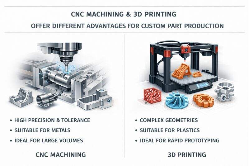
CNC vs 3D Printing Decision Points
The fundamental difference between these processes comes down to "sculpting" versus "building." CNC machining starts with a solid block and removes material to reveal your part. 3D printing builds layer by layer from nothing, adding material only where needed.
This distinction creates dramatically different strengths. According to LS Precision Manufacturing's analysis, rapid CNC prototyping excels when you need high precision, superior strength, and excellent surface finish. CNC prototype machining delivers parts with isotropic material properties - meaning strength is equal in all directions - while 3D-printed parts often exhibit weak interlayer bonding that fails under impact.
But here's where 3D printing wins: complex internal geometries that would be impossible or prohibitively expensive to machine. Think conformal cooling channels, lightweight lattice structures, or integrated assemblies that eliminate fasteners entirely. When your design includes features a cutting tool simply cannot reach, additive manufacturing becomes the only viable option.
The cost crossover point matters too. For fewer than 10 plastic parts, 3D printing typically costs less because it eliminates the programming and fixture setup expenses that burden low-volume CNC work. As quantities climb above 50-100 units, CNC machining's per-unit economics improve dramatically while 3D printing costs remain relatively flat.
Consider cnc prototyping when you need:
- Functional testing: Parts that must withstand real-world loads, temperatures, and wear
- Precision fits: Assemblies requiring tolerances tighter than ±0.005"
- Production-representative materials: Actual aluminum, steel, or engineering-grade plastics
- Smooth surface finishes: Components visible to end users or requiring sealing surfaces
Choose 3D printing when your project demands:
- Speed over precision: First articles needed in hours, not days
- Complex internal features: Channels, lattices, or hollow structures
- Design iteration: Multiple versions for rapid testing and refinement
- Very low quantities: One to five units where setup costs dominate
When Injection Molding Makes More Sense
If you're planning production runs exceeding 500-1,000 identical plastic parts, injection molding deserves serious consideration. Yes, tooling costs run $5,000 to $50,000+ depending on complexity. But once that mold exists, per-unit costs plummet to levels CNC machining simply cannot match.
According to Protolabs' manufacturing comparison data, injection molding delivers unmatched consistency and repeatability for high-volume production. Every part emerges virtually identical - critical for consumer products, medical devices, and automotive components where variation causes problems.
The trade-off? Lead time. Traditional injection molding requires weeks or months to design, machine, and validate tooling before production begins. This makes it poorly suited for prototype machining or applications where design changes remain likely.
Die casting follows similar economics for metal parts. High upfront tooling investment pays off through extremely low per-unit costs at scale, but only makes sense when you're confident your design is final and quantities justify the initial expense.
Sheet metal fabrication offers another alternative for enclosures, brackets, and structural components. Laser cutting, bending, and welding operations often produce large, lightweight parts more economically than machining from solid stock - particularly when wall thickness remains consistent.
| Manufacturing Method | Ideal Quantity | Material Options | Typical Tolerance | Lead Time | Cost Structure |
|---|---|---|---|---|---|
| CNC Machining | 1-500 units | Metals, plastics, composites | ±0.001" to ±0.005" | Days to weeks | Moderate setup, linear scaling |
| 3D Printing | 1-50 units | Polymers, some metals | ±0.005" to ±0.015" | Hours to days | Low setup, flat per-unit cost |
| Injection Molding | 500+ units | Thermoplastics | ±0.002" to ±0.005" | Weeks (tooling) | High setup, very low per-unit |
| Die Casting | 1,000+ units | Aluminum, zinc, magnesium | ±0.005" to ±0.015" | Weeks (tooling) | High setup, very low per-unit |
| Sheet Metal | 10-1,000 units | Steel, aluminum, stainless | ±0.010" to ±0.030" | Days to weeks | Low setup, moderate per-unit |
Hybrid Manufacturing Approaches
What if you didn't have to choose just one process? Increasingly, the smartest manufacturing strategies combine technologies to capture the benefits of each while minimizing their limitations.
As Manufacturing Tomorrow reports, hybrid manufacturing integrates 3D printing's design freedom with CNC machining's precision finishing. The workflow typically unfolds in two stages: first, 3D print a near-net-shape part with complex internal features; then, CNC machine critical interfaces, threads, and sealing surfaces to exact specifications.
This approach unlocks several compelling advantages:
- Functional prototypes faster: Parts with optimal performance characteristics ready for real-world testing
- Reduced material waste: Print only what you need, then machine only critical features
- Design freedom without compromise: Internal complexity plus external precision in the same component
Consider carbon fiber prototyping applications where lightweight strength matters. 3D printing can create the core structure while CNC machining finishes mounting interfaces and precision bores. The result combines additive manufacturing's weight savings with subtractive manufacturing's accuracy.
Prototype machining services often recommend a staged approach for product development: 3D print initial concepts for quick evaluation, CNC machine refined prototypes for functional testing, then transition to injection molding or die casting for production volumes. This progression optimizes cost and speed at each development phase.
The honest assessment? CNC prototype work isn't always the answer - but understanding when it is, and when alternatives serve you better, saves money and accelerates timelines. The best manufacturing partners help you navigate these decisions rather than pushing their preferred process regardless of fit.
With manufacturing method selected, the next consideration becomes industry-specific requirements that may constrain your options or demand particular certifications from your supplier.
Industry-Specific Requirements and Certifications
Here's something most machine shops gloss over in their marketing: certifications aren't just fancy logos for a website. They represent fundamentally different ways of running operations, documenting work, and ensuring quality. When your parts end up in aircraft, medical devices, or automotive safety systems, the standards governing their production become non-negotiable requirements rather than nice-to-have credentials.
Understanding what each industry demands helps you evaluate potential suppliers beyond surface-level claims. Let's examine what actually separates certified manufacturers from those simply claiming capability.
Automotive Supply Chain Requirements
The automotive industry operates under some of the most demanding quality frameworks in manufacturing. IATF 16949 certification represents the global standard for automotive quality management, building upon ISO 9001 while adding sector-specific requirements that address the unique pressures of automotive supply chains.
According to IATF research data, automotive OEM data shows that 90% of manufacturing companies certified to IATF 16949 maintain customer satisfaction, compared to only 73% of those certified solely to ISO 9001. That 17-point gap reflects the additional rigor built into automotive-specific requirements.
What makes IATF 16949 different? The standard covers 16 key areas that go beyond generic quality management:
- Customer Specific Requirements (CSR): Each automotive OEM maintains unique specifications that certified suppliers must integrate into their processes
- Product Safety: Mandatory emphasis on safety-critical components with coherent regulatory and industry-driven requirements
- FMEA and Risk Analysis: Specific mandated tools for analyzing and preventing potential failure modes
- Control Plans: Enhanced production controls including Statistical Process Control (SPC) to ensure parts meet specifications throughout production runs
- PPAP (Production Part Approval Process): Thorough product and manufacturing process approval before production begins
The PPAP requirement deserves special attention. Before shipping production parts, certified suppliers must demonstrate their processes consistently produce components meeting all specifications. This includes dimensional reports, material certifications, process flow diagrams, and capability studies proving the manufacturing system performs within acceptable limits.
For example, Shaoyi Metal Technology maintains IATF 16949 certification with strict SPC quality controls, delivering high-tolerance automotive components with lead times as fast as one working day. This combination of certification and operational capability illustrates what production-ready automotive suppliers look like in practice.
Aerospace and Defense Standards
If automotive requirements seem demanding, aerospace cnc machining raises the bar even higher. AS9100 certification builds upon ISO 9001 with additional requirements specific to the aerospace sector, emphasizing risk management, stringent documentation, and product integrity control throughout complex supply chains.
What distinguishes aerospace machining from other precision work?
- Material Traceability: Complete documentation tracking every material lot from mill certification through finished component - essential for investigating any in-service failures
- Configuration Management: Rigorous control of design changes ensuring parts match current approved specifications
- First Article Inspection: Comprehensive dimensional verification of initial production units before full production release
- Special Process Controls: NADCAP accreditation often required for heat treating, chemical processing, and nondestructive testing
CNC machining aerospace components frequently involves exotic materials like titanium alloys, Inconel, and specialty alloys requiring kovar machining services for specific thermal expansion properties. These materials demand specialized cutting strategies, tooling, and process controls that general-purpose machine shops often lack.
The tolerance requirements in aerospace applications often push into the ±0.0005" range or tighter for critical interfaces. Achieving these specifications consistently requires not just capable equipment but validated processes, calibrated measurement systems, and experienced machinists who understand the stakes involved.
Medical Device Machining Considerations
Medical machining operates under a completely different regulatory framework centered on patient safety. ISO 13485 certification specifically addresses quality management systems for medical devices, outlining strict controls over design, manufacturing, traceability, and risk mitigation.
According to PTSMAKE's medical manufacturing analysis, even deviations of a few micrometers can mean the difference between a successful procedure and a medical emergency. This zero-tolerance environment demands exceptional precision and documentation at every step.
Medical device machining requirements include:
- FDA Registration and Compliance: Manufacturers serving the U.S. market must follow 21 CFR Part 820 (Quality System Regulation) with specific requirements for design controls, production controls, and corrective actions
- Biocompatible Materials: Components contacting the human body require materials tested per ISO 10993 for biocompatibility - titanium alloys, specific stainless steel grades, and medical-grade polymers like PEEK
- Cleanroom Manufacturing: Many medical components require controlled environments classified per ISO 14644-1 standards to prevent contamination
- Complete Traceability: Every component must be traceable to specific material lots, machine operations, operators, and inspection results
- Validated Processes: Manufacturing processes must be formally validated to demonstrate consistent capability before production release
Surface finish requirements for medical components often exceed those of other industries. Implantable devices typically require Ra values between 0.1-0.4 μm to prevent bacterial adhesion and tissue irritation. Achieving and verifying these specifications requires specialized finishing operations and precision measurement equipment.
The documentation burden for medical device machining far exceeds general manufacturing. Device History Records (DHRs) must capture every detail of production, from incoming material inspection through final testing. This paperwork isn't bureaucratic overhead - it's the foundation for investigating any field issues and demonstrating regulatory compliance during FDA inspections.
Why Industry Experience Matters
Certifications verify that systems and procedures exist. They don't guarantee that a shop understands the nuances of your specific industry. A newly certified medical device manufacturer lacks the institutional knowledge that comes from years of navigating FDA expectations, handling customer audits, and solving industry-specific manufacturing challenges.
When evaluating potential machining partners, look beyond the certification list to assess actual experience:
- Customer base: Do they currently serve companies in your industry? Can they provide references?
- Audit history: How have they performed during customer and third-party audits?
- Problem-solving capability: Can they describe how they've resolved industry-specific manufacturing challenges?
- Technical knowledge: Do their engineers understand industry terminology, specifications, and common requirements?
The difference between a certified shop and an experienced industry partner often becomes apparent only when problems arise. Shops with deep industry knowledge anticipate issues before they occur, understand the implications of specification deviations, and communicate effectively using industry-specific language.
For general industrial applications without specific certification requirements, these considerations matter less. But when your components must meet aerospace, medical, or automotive standards, choosing a partner with genuine industry expertise - not just certificates on the wall - significantly reduces project risk and accelerates time to production.

How to Prepare for a Custom Machining Project
You've selected your manufacturing process, chosen materials, and understand tolerance requirements. Now comes the moment that separates smooth projects from frustrating ones: preparing your documentation package. Whether you're searching for a cnc machine shop near me or partnering with a specialized manufacturer overseas, the quality of your preparation directly determines quote accuracy, lead time, and final part quality.
Think of your RFQ (Request for Quotation) as more than a price request - it's the foundational document defining what "done right" looks like. According to industry research, a vague or incomplete RFQ can add 20-40% to project costs through miscommunication, rework, and unnecessary back-and-forth. Let's ensure yours doesn't fall into that trap.
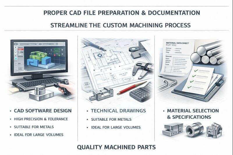
Preparing Your CAD Files
Your 3D model serves as the source of truth for everything that follows. As Randy Altschuler, CEO of Xometry, notes: "An accurate, information-rich 3D CAD model is the single most important element in getting a fast, accurate quote and a high-quality part."
Here's what your file package should include:
- Export your 3D model as a .STEP file. This universal format transfers geometry accurately between different CAD/CAM systems. Most machinist shops near me and global suppliers accept STEP as the standard. IGES works as an alternative but may lose some feature data during translation.
- Create a 2D technical drawing in PDF format. This drawing serves as the master specification, defining tolerances, GD&T callouts, surface finish requirements, and material specifications that the 3D model cannot fully capture.
- Ensure consistency between 3D and 2D files. As Greg Paulsen from Fictiv explains, "We often see a disconnect between the 3D model and the 2D drawing... A successful RFQ package is one where the 2D drawing serves to clarify and add critical information that complements the 3D model, rather than contradicting it."
- Include native CAD files when possible. While not always required, native formats (SolidWorks, Inventor, Fusion 360) preserve design intent and feature history that can help manufacturers understand your part better.
Common file preparation mistakes include submitting mesh files (STL) instead of solid models, providing drawings with outdated revisions that don't match the 3D geometry, and omitting critical dimensions that only appear in your original design but weren't included in exports.
Essential RFQ Information
Beyond technical files, your RFQ should provide context that helps suppliers quote accurately and identify potential issues early. According to Mectalent's RFQ guidelines, including comprehensive details speeds up the quoting process and prevents costly assumptions.
Your RFQ should clearly specify:
- Material requirements: Specify exact alloy grades (6061-T6, not just "aluminum") and whether you'll supply material or expect the shop to source it
- Quantity needed: Include both immediate needs and projected annual volumes if applicable
- Delivery timeline: Distinguish between "need by" dates and actual deadline flexibility
- Industry requirements: Note if parts require specific certifications, traceability documentation, or compliance with standards like AS9100 or ISO 13485
- Surface treatment needs: Specify any post-machining processes like anodizing, plating, or heat treatment
- Inspection requirements: Define what documentation you need - first article inspection reports, material certifications, dimensional reports
Pro tip: Include a simple "Key Dimension Inspection Plan" listing your 3-5 most critical features and their inspection requirements. This demonstrates engineering rigor and helps suppliers price inspection appropriately rather than assuming 100% verification of every dimension.
Design Mistakes That Increase Costs
Even experienced engineers fall into design traps that silently inflate machining costs. According to XTJ Precision Manufacturing's analysis, these common mistakes can increase part costs by 25-40%:
- Unnecessary tight tolerances: Specifying ±0.005mm on non-critical features when standard tolerances would work doubles production time and increases scrap rates
- Deep pockets with small radii: Internal corners requiring long, thin tools that deflect easily demand slower feeds and multiple passes
- Thin walls without support: Features that vibrate during machining require careful feeds and potentially custom fixturing
- Undercuts and inaccessible features: Geometries requiring 4th or 5th axis setups when 3-axis would suffice if slightly redesigned
- Over-specifying surface finish: Requesting Ra 0.8 μm when Ra 3.2 μm meets functional requirements adds grinding or polishing operations
The solution? Request a Design for Manufacturability (DFM) review before finalizing your order. Reputable suppliers will identify cost-saving opportunities and suggest modifications that maintain function while improving manufacturability.
Questions to Ask Potential Suppliers
When evaluating local machine shops or specialized manufacturers, these questions reveal capability and fit:
- What file formats do you prefer, and can you work with my CAD system's native files?
- Do you provide DFM feedback as part of your quoting process?
- What's your typical lead time for projects similar to mine?
- How do you handle engineering changes after production begins?
- What inspection and documentation is included in your standard pricing?
- Can you scale from prototype quantities to production volumes?
Lead time optimization often comes down to communication speed and design choices. Shops can typically expedite projects when customers provide complete documentation upfront, respond quickly to clarification requests, and design parts compatible with standard tooling and fixturing.
With your documentation package prepared and supplier questions ready, the final step involves evaluating potential partners and understanding what separates adequate suppliers from exceptional ones.
Choosing the Right Custom Machining Partner
You've done the homework - understood processes, selected materials, optimized tolerances, and prepared flawless documentation. Now comes the decision that determines whether all that preparation pays off: selecting the right manufacturing partner. The wrong choice here can unravel even the best-prepared projects, while the right partner transforms complex requirements into precision cnc machining parts delivered on time and on spec.
So how do you separate genuinely capable suppliers from those who simply talk a good game? Let's walk through the evaluation criteria that actually matter.
Evaluating Machining Partners
Think of supplier selection like hiring a critical team member. Credentials matter, but so does fit, communication style, and proven track record. According to Modus Advanced's selection framework, the best CNC machining shop partners excel across multiple dimensions beyond just price.
Here's what to evaluate when comparing precision machining companies:
- Technical capabilities: Do they have the specific equipment your parts require? A shop claiming 5-axis capability but outsourcing complex work isn't truly capable - they're a broker
- Quality certifications: Match certifications to your industry needs - IATF 16949 for automotive, AS9100 for aerospace, ISO 13485 for medical
- Communication responsiveness: How quickly do they respond to RFQs? Slow quotes often predict slow problem resolution during production
- DFM feedback quality: The best partners provide meaningful design feedback that saves you money, not just price quotes
- Inspection and documentation: Can they provide the quality records your application requires?
- References and track record: Ask for customers in similar industries and actually call them
One revealing test: send your technical package and wait for questions. Partners who respond with thoughtful clarifications demonstrate engagement and expertise. Those who quote immediately without questions either got lucky - or made assumptions that could become expensive surprises.
From Prototype to Production Scale
Here's a scenario that trips up many engineering teams: you find a great cnc turning services provider for prototypes, but when production quantities ramp up, they can't scale. Suddenly you're qualifying new suppliers mid-project, losing months of schedule and accumulated learning.
According to UPTIVE's prototype-to-production research, selecting the right partner with relevant experience can potentially save thousands of dollars because they're familiar with common pitfalls and the most effective ways to steer clear of them.
When evaluating custom cnc machining services for projects with production potential, consider:
- Capacity headroom: Can they handle 10x your prototype volume without major lead time increases?
- Process consistency: Do they use SPC and documented procedures that ensure part 500 matches part 5?
- Tooling management: How do they handle tool wear and replacement across extended runs?
- Inventory programs: Can they hold safety stock or implement kanban systems for ongoing demand?
For example, Shaoyi Metal Technology demonstrates this scalability approach - offering rapid prototyping with lead times as fast as one working day while maintaining IATF 16949 certification and SPC controls that support seamless transition to mass production volumes. This combination of speed and quality systems represents what production-ready partners look like.
Local vs Specialized Manufacturers
Should you prioritize finding machining shops near me or work with specialized manufacturers regardless of location? According to APCL Group's sourcing analysis, each approach carries distinct trade-offs.
Local partners offer:
- Faster communication with aligned time zones
- Easier on-site visits and quality audits
- Shorter shipping times and lower logistics complexity
- Greater flexibility for urgent orders and design changes
Specialized manufacturers provide:
- Deep expertise in specific industries or processes
- Often lower production costs at scale
- Access to specialized equipment or materials
- Established quality systems for demanding applications
The honest answer? It depends on your priorities. For prototype development with frequent iterations, local shops often win on speed and flexibility. For production volumes with stable designs, specialized manufacturers - whether domestic or international - may deliver better economics and consistency.
Your Next Steps
You now understand what most buyers learn only through expensive trial and error: how machining processes affect costs, why material and tolerance choices matter, what certifications actually mean, and how to prepare documentation that gets accurate quotes.
Here's your action plan:
- Finalize your technical package with complete 3D models, 2D drawings, and clear specifications
- Identify 3-5 potential partners whose capabilities match your requirements
- Request detailed quotes with line-item breakdowns, not just total prices
- Evaluate DFM feedback quality as a predictor of partnership potential
- Start with a small order to validate quality and communication before committing to production volumes
Custom part machining doesn't have to be mysterious or frustrating. With the knowledge from this guide, you're equipped to navigate the process confidently, ask the right questions, and build partnerships that deliver precision components on time and on budget. The shops that seemed intimidating before? They're now potential partners waiting to turn your designs into reality.
Frequently Asked Questions About Custom Part Machining
1. What is custom CNC machining and how does it differ from standard parts?
Custom CNC machining creates components specifically designed and manufactured to meet unique specifications using precision equipment. Unlike mass-produced standard parts with fixed dimensions, custom machined parts are tailored to exact requirements including geometry, tolerances as tight as 0.003-0.005 inches, material selection from metals like aluminum and titanium to engineering plastics like Delrin and nylon, and surface finishes. This process serves industries where standard off-the-shelf components cannot meet specific design requirements, compatibility needs, or performance demands.
2. How much does custom CNC machining cost?
Custom CNC machining costs depend on several factors: machine time (3-axis mills run $70-$125/hour while 5-axis machines cost $150-$250/hour), setup and programming fees ($200-$500 typically), material costs, tolerance requirements, and finishing operations ($10-$70+ per part). A single aluminum prototype might cost $500, but ordering 10 units drops per-piece pricing to around $300, and quantities of 50+ can reduce costs by up to 60%. Design optimization through DFM principles can slash costs by 20-40% without compromising function.
3. What materials can be used for custom machined parts?
Custom machining supports a wide range of materials including aluminum alloys (6061 for versatility, 7075 for high-strength applications), steels (1045 carbon steel, stainless 304/316, tool steels), specialty metals (titanium, bronze, brass), and engineering plastics (Delrin/acetal for dimensional stability, nylon for impact resistance, polycarbonate for optical clarity, PTFE for chemical resistance). Material selection affects machinability, cost, and final part performance, with aluminum machining 3-4x faster than stainless steel.
4. How long does custom CNC machining take?
Lead times for custom CNC machining typically range from days to weeks depending on part complexity, quantity, and supplier capacity. Prototype runs of 1-5 units often have faster turnaround but higher per-unit costs due to setup time. Some certified manufacturers like Shaoyi Metal Technology offer lead times as fast as one working day for high-tolerance components. Factors affecting lead time include design complexity, material availability, tolerance requirements, finishing operations, and how quickly customers respond to clarification requests during the quoting process.
5. What certifications should a custom machining supplier have?
Required certifications depend on your industry. Automotive applications typically require IATF 16949 certification with PPAP compliance and SPC quality controls. Aerospace machining demands AS9100 certification with complete material traceability and NADCAP accreditation for special processes. Medical device machining requires ISO 13485 certification, FDA compliance, and biocompatible material documentation. Beyond certifications, evaluate actual industry experience through customer references, audit history, and demonstrated problem-solving capability in your specific sector.