 Small batches, high standards. Our rapid prototyping service makes validation faster and easier —

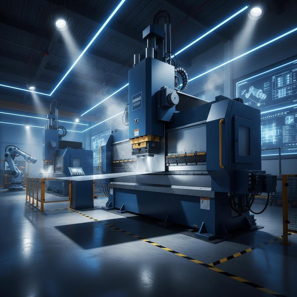
CNC Sheet Metal Forming: 9 Essential Points From Design To Partner Selection
What CNC Sheet Metal Forming Actually Means
Ever wondered how manufacturers transform flat metal sheet into perfectly angled brackets, complex enclosures, or precision automotive components? The answer lies in a process that has revolutionized modern manufacturing: CNC sheet metal forming.
CNC sheet metal forming is a manufacturing process where computer-programmed instructions control machinery that bends, punches, stamps, and shapes flat metal sheets into precise three-dimensional parts with repeatable accuracy.
Understanding the cnc meaning in this context is essential. CNC stands for Computer Numerical Control, a system where digital commands replace manual operation. Instead of a technician manually adjusting machine settings for each bend or cut, pre-programmed software dictates every movement with exacting precision.
From Flat Stock to Precision Parts
The fundamental principle behind this technology is surprisingly straightforward. You start with a flat metal sheet, feed it into CNC-controlled machinery, and the system executes programmed instructions to create your desired shape. These instructions, typically derived from CAD designs and converted into machine-readable G-code, control everything from tool paths to feed rates and bend angles.
Think of it like this: traditional metal fabrication relied heavily on the skill and consistency of individual operators. One experienced worker might produce excellent results, while another could introduce slight variations. CNC forming eliminates this variability by ensuring every single part follows identical digital instructions.
The Digital Revolution in Metal Shaping
What makes cnc sheet metal forming so transformative? It bridges the gap between digital design and physical production. Your engineering team creates a 3D model in CAD software, and that design translates directly into machine movements. According to industry experts, high-end CNC machines can achieve tolerances as close as ±0.0002 inches, a level of precision that manual methods simply cannot match consistently.
This digital integration also means faster revisions. When a client changes specifications, you're just a few clicks away from updating the entire production process. No need to retrain operators or create new physical templates.
Why Automation Changes Everything
The shift from manual to automated sheet metal fabrication delivers benefits that compound over time:
- Repeatability: Once programmed, a CNC forming machine can produce hundreds or thousands of identical parts with minimal variation
- Reduced labor dependency: Operations require less hands-on supervision, freeing skilled workers for quality control and complex problem-solving
- Material efficiency: Precise control means less scrap and wasted material, directly impacting your bottom line
- Documentation: Every job is digitally recorded, making repeat orders and quality tracking straightforward
This technology matters across virtually every manufacturing sector. Automotive companies rely on cnc forming for chassis mounts and structural brackets. Aerospace manufacturers depend on it for lightweight aluminum components where precision equals safety. Electronics firms use it to create server racks and device housings with tight tolerances. Even construction and architecture benefit through uniform metal trims, panels, and decorative elements.
Whether you're evaluating metal fabrication partners or considering equipment investments, understanding these fundamentals positions you to make smarter decisions. The following sections will explore specific techniques, material considerations, and practical guidelines that build on this foundation.
The Complete Guide to CNC Forming Techniques
Now that you understand what CNC sheet metal forming means, let's explore the specific techniques available to you. Choosing the right method can mean the difference between cost-effective production and budget overruns. Each sheet metal forming machine operates on different principles and excels at different applications.
Before diving into individual methods, it's worth clarifying an important distinction. Subtractive processes like laser cutting remove material to create shapes. Formative processes, which we're focusing on here, reshape metal without removing it. While laser cutting cutting operations might prepare blanks for forming, the bending and shaping that follows preserves your material investment.
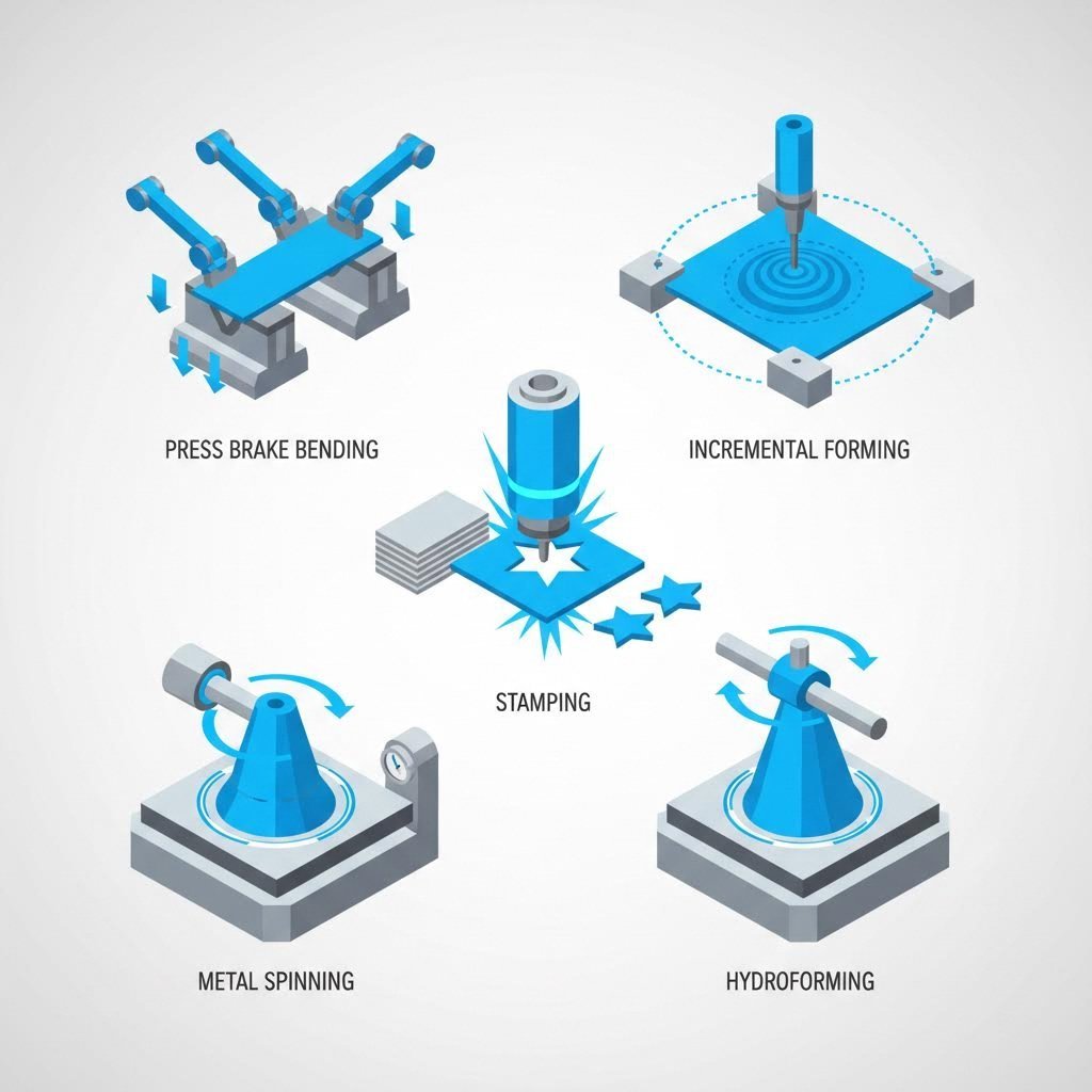
CNC Bending and Panel Forming
When most manufacturers think of CNC forming, they picture a metal bending machine in action. Press brakes and panel benders dominate this category, and for good reason.
CNC Press Brakes use a punch and die system to create precise bends. The flat sheet is positioned between these tools, and the punch descends with controlled force to form angles ranging from shallow bends to sharp 90-degree corners. Modern press brakes feature backgauges that automatically position material for each bend in a sequence, achieving remarkable consistency across production runs.
Panel Benders take a different approach. Instead of moving the entire sheet between bends, a panel bender holds the material stationary while bending blades move around it. This makes them ideal for larger panels and complex parts requiring multiple bends in quick succession. If you're producing HVAC enclosures, electrical cabinets, or architectural panels, a panel bender often proves more efficient than traditional press brake operations.
Both methods excel at producing brackets, enclosures, chassis components, and structural parts. The choice between them typically depends on part size, complexity, and production volume requirements.
Incremental and Spinning Methods
Incremental Sheet Forming (ISF) represents a fundamentally different philosophy. Rather than using matched tooling to create shapes in single operations, ISF uses a simple stylus tool that traces programmed paths across clamped sheet metal. Each pass deforms the material slightly, and accumulated passes gradually create complex three-dimensional geometries.
Single-point incremental forming uses one tool working against a backing plate or die. Two-point incremental forming adds a second tool working from the opposite side, enabling more complex shapes and tighter tolerances. This metal forming machine category shines in prototyping and low-volume production because it eliminates the need for expensive matched dies. Imagine prototyping a new automotive panel without investing in die cut machine tooling that costs tens of thousands of dollars.
CNC Spinning creates rotationally symmetric parts by pressing sheet metal against a rotating mandrel. Think of it like pottery on a wheel, but with metal. As the workpiece spins, rollers or tools progressively shape it against the mandrel form. This technique produces everything from cookware and lighting reflectors to aerospace nose cones and pressure vessel components.
Spinning excels when you need seamless, curved surfaces without welds. The process also work-hardens the material, often improving strength compared to the original sheet stock.
Hydroforming and Stamping Approaches
Hydroforming uses pressurized fluid to push sheet metal into a die cavity. The even pressure distribution creates smooth, complex curves with excellent surface finish and uniform wall thickness. Automotive manufacturers favor hydroforming for structural components like subframes and crossmembers because it produces lightweight, strong parts with fewer welds than traditional fabrication methods.
Sheet hydroforming typically uses a rubber diaphragm backed by hydraulic fluid to press material into a single-sided die. Tube hydroforming, a related process, expands tubular blanks into complex hollow shapes.
CNC Stamping combines speed with precision for high-volume production. Progressive die stamping moves sheet metal through a series of stations, with each station performing a specific operation: punching, bending, coining, or trimming. By the time material exits the final station, complex parts are complete.
While stamping requires significant tooling investment upfront, the per-part cost becomes extremely competitive at high volumes. Automotive brackets, electronic component housings, and appliance parts often justify stamping tooling through sheer production quantity.
| Method | Best Applications | Typical Materials | Production Volume Suitability |
|---|---|---|---|
| CNC Bending (Press Brake/Panel Bender) | Brackets, enclosures, chassis, structural components | Steel, aluminum, stainless steel, copper | Low to high volume |
| Incremental Sheet Forming | Prototypes, custom parts, complex curves | Aluminum, steel, titanium | Prototyping to low volume |
| CNC Spinning | Domes, cones, cylinders, reflectors | Aluminum, copper, stainless steel | Low to medium volume |
| Hydroforming | Automotive structural parts, aerospace components | Aluminum, steel, stainless steel | Medium to high volume |
| CNC Stamping | High-volume brackets, housings, precision parts | Steel, aluminum, copper, brass | High volume only |
Understanding these forming techniques helps you match your project requirements to the right process. A prototype needing five parts has very different economics than a production run of fifty thousand. The next section explores the technical specifications and tolerances each method can achieve, giving you concrete data for your manufacturing decisions.
Technical Specifications and Tolerances Explained
You've explored the forming techniques available. Now comes the question every engineer and purchasing manager asks: what tolerances can I actually achieve? Understanding technical specifications helps you set realistic expectations, communicate effectively with suppliers, and design parts that are both functional and manufacturable.
The specifications below vary between equipment types, manufacturers, and even individual machine condition. Treat these as representative ranges rather than absolute guarantees. Always confirm capabilities with your specific fabrication partner before finalizing designs.
Tolerance Standards You Can Expect
Different CNC forming methods deliver different precision levels. Your choice of process directly impacts what dimensional accuracy you can realistically specify. Here's what you'll typically encounter across the major forming techniques:
- CNC Press Brake Bending: Angular tolerance of ±0.5° to ±1°; dimensional tolerance of ±0.010" to ±0.030" (±0.25mm to ±0.76mm) depending on part length and complexity
- Panel Bending: Often tighter than press brakes at ±0.25° angular tolerance; dimensional accuracy around ±0.008" to ±0.015" (±0.20mm to ±0.38mm)
- Incremental Sheet Forming: Typically ±0.020" to ±0.040" (±0.5mm to ±1.0mm) for complex contours; achievable precision depends heavily on tool path programming
- CNC Spinning: Wall thickness tolerance around ±0.005" to ±0.015" (±0.13mm to ±0.38mm); diameter tolerance typically ±0.010" to ±0.020" (±0.25mm to ±0.50mm)
- Hydroforming: Dimensional tolerance of ±0.010" to ±0.020" (±0.25mm to ±0.50mm) with excellent surface finish consistency
- Progressive Die Stamping: Tightest tolerances at ±0.002" to ±0.005" (±0.05mm to ±0.13mm) for critical features; tooling quality directly impacts results
Keep in mind that tolerance stacking becomes a real concern with multi-bend parts. Each bend introduces potential variation, so a bracket with six bends will have more cumulative variation than one with two bends. Design with this reality in mind, especially when parts must mate with other components.
Material Thickness and Gauge Considerations
If you've worked with sheet metal suppliers, you've likely encountered gauge sizes rather than decimal thickness measurements. Understanding the sheet metal gauge chart system saves confusion and prevents costly ordering mistakes.
Here's where it gets tricky: gauge numbers are material-specific. A 14 gauge steel thickness measures 0.0747" (1.90mm), but 14 gauge aluminum is 0.0641" (1.63mm). That's a significant difference that could throw off your entire design. Similarly, 11 gauge steel thickness comes in at 0.1196" (3.04mm), considerably heavier than equivalent aluminum gauges.
The gauge size chart originates from 19th-century wire manufacturing, where the gauge number indicated how many times wire was drawn through reducing dies. Higher gauge numbers meant more draws and thinner wire. This historical quirk means gauge 20 is thinner than gauge 10, which confuses many newcomers to metal fabrication.
For CNC forming applications, typical material thickness ranges include:
- Thin Gauge (26-22 gauge): Approximately 0.018" to 0.031" (0.46mm to 0.79mm). Common for electronics enclosures, decorative panels, and lightweight applications. Requires careful handling to prevent distortion.
- Medium Gauge (20-14 gauge): Approximately 0.036" to 0.075" (0.91mm to 1.90mm). The sweet spot for most industrial applications including brackets, housings, and structural components.
- Heavy Gauge (12-7 gauge): Approximately 0.105" to 0.179" (2.67mm to 4.55mm). Used for heavy-duty structural parts, equipment frames, and applications requiring significant strength.
- Plate (1/4" and above): Beyond typical sheet metal gauge charts. Requires heavier equipment and often different forming approaches.
When reviewing a drill size chart or drill chart for hole placement in formed parts, remember that material thickness affects minimum hole-to-bend distances. Thicker materials generally require greater clearance between holes and bend lines to prevent distortion.
Size and Geometry Limitations
Maximum part size depends on your fabrication partner's specific equipment. However, general constraints exist across the industry:
Press brake capacity is typically defined by bed length and tonnage. Common configurations handle sheets up to 10-14 feet (3-4.3 meters) in length. Tonnage requirements increase with material thickness and bend length. A 12-foot bend in 10 gauge steel requires substantially more force than the same bend in 22 gauge aluminum.
Bend radii limitations tie directly to material properties and thickness. According to industry guidelines, a general rule suggests minimum inside bend radius should equal or exceed material thickness for most applications. Using a smaller bend radius than thickness increases cracking risk, particularly with harder materials or work-hardened alloys. Most economical designs use a single bend radius throughout, though multiple radii are achievable with appropriate tooling.
Minimum flange dimensions impose practical limits on how short a bent leg can be. Tooling geometry prevents extremely short flanges, and attempting them risks material slippage or tool interference. The minimum distance varies by equipment and tooling configuration, but expect restrictions in the range of 0.25" to 0.50" (6mm to 12mm) plus the bend radius for many standard setups.
Hole placement relative to bends matters significantly. Holes positioned too close to bend lines will distort during forming. Standard practice recommends maintaining a minimum distance equal to at least 2.5 times material thickness plus the bend radius between hole edges and bend lines. Round holes perpendicular to bend lines tolerate closer placement than elongated slots parallel to bends.
These specifications form the foundation for designing manufacturable parts. The next section explores how different sheet metal materials behave during forming, helping you select the right alloy for your specific application requirements.
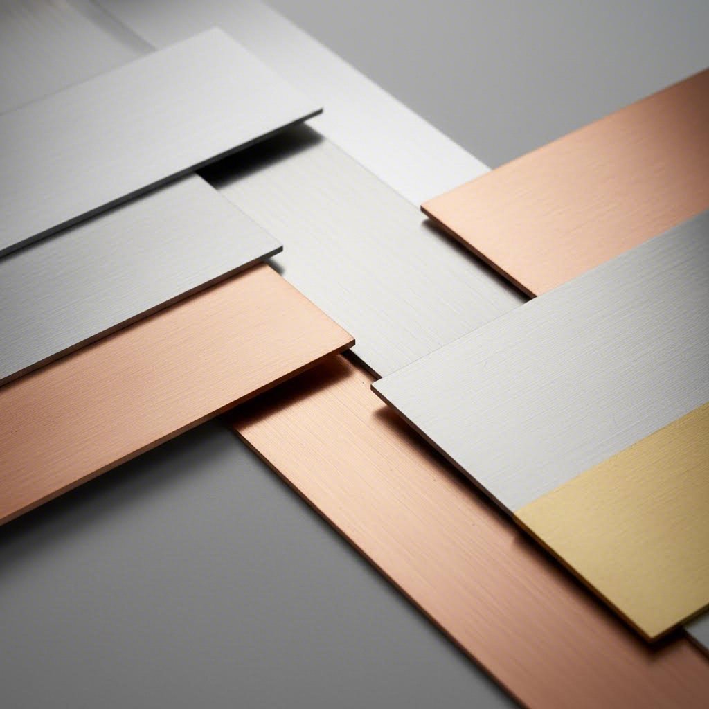
Choosing the Right Sheet Metal Material
You've learned about forming techniques and tolerances. Now comes a decision that affects every aspect of your project: which material should you use? The sheet metal you select determines tooling requirements, forming speeds, springback compensation, and ultimately whether your parts meet functional requirements.
Material selection isn't just about strength or cost. It's about understanding how different metals behave when you bend, stretch, and shape them. Some materials cooperate beautifully. Others fight you at every step. Knowing the difference saves time, money, and frustration.
Aluminum and Its Forming Advantages
When engineers need lightweight parts with excellent formability, aluminum sheet metal often tops the list. Aluminum alloys offer roughly one-third the weight of steel at comparable thicknesses, making them essential for aerospace, automotive, and portable equipment applications.
What makes aluminum sheet so cooperative during forming? Several properties work in your favor:
- High ductility: Aluminum stretches and bends without cracking, accommodating complex geometries that would challenge harder materials
- Lower tensile strength: Requires less force to form, reducing equipment wear and energy consumption
- Excellent thermal conductivity: Dissipates heat quickly during high-speed forming operations
- Natural corrosion resistance: The oxide layer that forms protects parts without additional coatings in many applications
However, aluminum presents one significant challenge: springback. According to research from the Auto/Steel Partnership, aluminum alloys exhibit approximately three times the springback of similar-strength steel due to their lower elastic modulus (around 70 GPa versus steel's 210 GPa). This means your tooling must compensate more aggressively, and achieving tight angular tolerances requires careful process control.
Common forming grades include 5052 (excellent formability for general applications), 6061 (good formability with higher strength after heat treatment), and 3003 (outstanding formability for deep draws and complex bends).
Steel Grades for CNC Forming
Mild Steel (Low Carbon Steel) remains the workhorse of metal fabrication. It's cost-effective, widely available, and forgiving during forming operations. With carbon content below 0.25%, mild steel offers excellent ductility while maintaining adequate strength for structural applications.
The predictable behavior of mild steel makes it ideal for learning new forming processes or establishing baseline parameters. Springback is manageable, work hardening is moderate, and tooling wear stays reasonable even at high production volumes.
Galvanized sheet metal adds corrosion protection through a zinc coating. The coating doesn't significantly affect formability, though you'll notice some differences in surface friction and the potential for coating flaking at tight bend radii. For outdoor applications or humid environments, galvanized steel often proves more economical than stainless alternatives.
Stainless steel sheet metal introduces both benefits and complications. The corrosion resistance, aesthetic appeal, and hygienic properties of stainless steel sheet make it indispensable for food processing, medical equipment, architectural features, and marine applications.
However, stainless steel forms differently than mild steel. Higher tensile strength means greater forming forces and accelerated tool wear. More importantly, stainless exhibits significant work hardening during deformation. Each bend or stretch increases the material's resistance to further forming, which can lead to cracking in complex parts if you don't plan your forming sequence carefully.
316 stainless steel deserves special mention. This marine-grade alloy offers superior corrosion resistance compared to the more common 304 grade, particularly in chloride environments. But 316 stainless steel also presents more forming challenges due to its higher work hardening rate. Expect tighter bend radii limitations and the need for more generous springback compensation when working with this alloy.
Springback in stainless steel can be substantial. The combination of high yield strength and significant work hardening creates elastic stresses that want to return the material toward its original flat state. Successful forming often requires overbending by 2-5 degrees beyond the target angle, though exact compensation depends on grade, thickness, and bend geometry.
Specialty Metals and Their Challenges
Copper offers exceptional electrical and thermal conductivity, making it essential for electrical components, heat exchangers, and decorative applications. Pure copper forms easily thanks to its high ductility, but it's soft enough that handling marks and tool impressions show readily. Work hardening occurs during forming, which actually benefits applications requiring springy contacts or improved mechanical properties.
Brass combines copper with zinc to create an alloy that machines and forms well while offering an attractive gold-like appearance. When comparing brass vs bronze, remember that brass (copper-zinc) generally forms more easily than bronze (copper-tin). Bronze offers better wear resistance and strength but requires more careful forming approaches to avoid cracking.
Both copper and brass find extensive use in electrical connectors, plumbing fittings, musical instruments, and architectural hardware. Their antimicrobial properties also make them increasingly popular for high-touch surfaces in healthcare and public spaces.
For any specialty metal, consult your fabrication partner about their specific experience. Material-specific tooling, adjusted forming speeds, and appropriate lubrication can mean the difference between success and scrap.
| Material | Formability Rating | Key Considerations | Common Applications |
|---|---|---|---|
| Aluminum Alloys (5052, 6061, 3003) | Excellent | High springback (3x steel); lightweight; requires careful tooling compensation | Aerospace panels, automotive components, electronics enclosures, architectural trim |
| Mild Steel (Low Carbon) | Excellent | Predictable behavior; moderate springback; cost-effective; requires corrosion protection | Structural brackets, chassis components, general fabrication, industrial equipment |
| Galvanized Steel | Good to Excellent | Zinc coating may flake at tight radii; good corrosion resistance; similar forming to mild steel | HVAC ductwork, outdoor enclosures, agricultural equipment, construction components |
| Stainless Steel (304, 316) | Moderate | Significant work hardening; high springback; requires greater forming forces; excellent corrosion resistance | Food processing equipment, medical devices, marine hardware, architectural features |
| Copper | Excellent | Very soft; shows handling marks easily; work hardens during forming; high conductivity | Electrical components, heat exchangers, roofing, decorative applications |
| Brass | Good to Excellent | Forms more easily than bronze; attractive appearance; good machinability; moderate work hardening | Electrical connectors, plumbing fittings, musical instruments, decorative hardware |
Understanding these material characteristics helps you make informed decisions before cutting the first blank. The right material choice simplifies forming, reduces scrap, and delivers parts that perform as intended. With material selection covered, the next section walks through the complete CNC forming workflow from initial CAD design to finished, inspected parts.
The CNC Forming Process From Start to Finish
You've selected your forming technique and chosen your material. Now what? How does a digital design file actually become a precision-formed metal part sitting on your shipping dock? This is where many guides fall short, skipping the practical workflow that connects design intent to physical reality.
Understanding this process helps you communicate more effectively with fabrication partners, anticipate potential bottlenecks, and design parts that flow smoothly through production. Whether you're managing a product development timeline or evaluating supplier capabilities, knowing what happens at each stage gives you a significant advantage.
From CAD File to Machine Code
The journey from concept to formed part begins in CAD software. Your engineering team creates a 3D model that defines every dimension, angle, and feature of the finished component. But a CNC machine sheet metal equipment can't read native CAD files directly. The translation process involves several critical steps.
CAD Design and File Preparation establishes the foundation. Modern CAD platforms like SolidWorks, Fusion 360, and Autodesk Inventor include dedicated sheet metal toolsets that understand forming constraints. These tools automatically calculate flat pattern layouts, accounting for bend allowances and material stretching. Clean geometry matters here—open surfaces, overlapping elements, or ambiguous dimensions create problems downstream.
Export formats depend on your workflow. STEP files (.step/.stp) offer universal compatibility for 3D geometry. DXF files work well for 2D profiles, particularly when laser or plasma cutting prepares blanks before forming. According to industry sources, STEP remains the most reliable format for CNC machining and forming applications due to its broad software support.
CAM Programming and Toolpath Generation transforms your design into machine-readable instructions. CAM (Computer-Aided Manufacturing) software imports your geometry and generates the G-code that controls machine movements. For a sheet metal bending machine, this includes defining bend sequences, calculating ram stroke depths, setting backgauge positions, and specifying tonnage requirements.
This is where experienced programmers earn their value. The software determines optimal bend sequencing to avoid tool collisions—situations where an already-formed flange would interfere with subsequent operations. It calculates springback compensation based on material properties and specifies which tooling to install at each station.
Simulation software plays an increasingly important role here. Before any metal moves, virtual simulations predict how the part will form, flagging potential collisions, excessive thinning, or cracking risks. Catching these issues digitally costs nothing compared to scrapping physical parts or damaging expensive tooling.
The Forming Operation Step by Step
With programming complete, production moves to the shop floor. Here's the complete workflow from raw material to formed part:
- Material Preparation and Loading: Operators verify incoming sheet metal against specifications, checking thickness, grade, and surface condition. Blanks are cut to size if not already prepared, often using laser or shear cutting. The kerf—material removed during cutting—must be accounted for in blank dimensions. Clean, properly sized blanks load into the sheet metal machine for forming.
- Machine Setup and Calibration: Following the CAM-generated setup sheet, operators mount specified punches and dies. Modern press brakes feature hydraulic quick-clamping systems that reduce changeover time from minutes to seconds. Critical alignment checks verify that punch tips center precisely over die grooves. Backgauge positions are calibrated, and ram stroke depths are confirmed against programmed values.
- Test Bends and First Article Inspection: Before committing to production quantities, operators run test pieces. These first articles undergo thorough dimensional inspection, verifying bend angles, flange lengths, and overall geometry against specifications. Any deviations trigger program adjustments before full production proceeds.
- Production Forming: With setup verified, the metal forming machines execute programmed sequences automatically. The operator positions each blank against the backgauge, initiates the cycle, and the machine performs each bend precisely as programmed. For multi-bend parts, the backgauge repositions automatically between operations, maintaining consistent part-to-part accuracy.
- In-Process Quality Monitoring: Quality control extends beyond final inspection. Operators perform periodic dimensional checks throughout production runs, catching drift before it produces scrap. Advanced systems include real-time angle measurement that automatically compensates for material variations, adjusting ram depth on the fly to maintain target angles.
Quality Control and Finishing
Forming metal sheet is only part of the equation. What happens after parts leave the press brake determines whether they're truly ready for assembly or shipment.
Quality Inspection and Verification confirms that finished parts meet specifications. Dimensional checks use calibrated instruments—calipers, micrometers, coordinate measuring machines, and optical comparators—to verify critical features. First article inspection reports document compliance for quality records and customer approval. Statistical process control tracks trends across production runs, identifying drift before it creates nonconforming parts.
Visual inspection catches surface defects that dimensional tools miss: scratches, tool marks, coating damage, or inconsistent finishes. For aesthetic applications, surface quality standards define acceptable appearance criteria.
Secondary Operations prepare parts for their intended use:
- Deburring: Forming and cutting operations often leave sharp edges or burrs that pose safety hazards and assembly problems. Manual deburring, tumbling, or specialized deburring equipment removes these imperfections.
- Hardware Installation: Many formed parts require threaded inserts, clinch nuts, or self-clinching standoffs installed after forming. Press operations insert this hardware without damaging formed features.
- Surface Finishing: Depending on application requirements, parts may proceed to powder coating, painting, plating, or other finishing processes. Some parts require masking to protect threaded holes or mating surfaces during finishing.
- Assembly: Complex assemblies may combine multiple formed components with fasteners, welding, or adhesive bonding before final inspection and packaging.
Throughout this workflow, documentation tracks each part's journey. Lot numbers, inspection records, and process parameters create traceability that proves invaluable when questions arise about specific shipments or production runs.
Understanding this end-to-end process reveals why experienced fabrication partners deliver better results than shops simply operating equipment. The difference lies in process discipline, quality systems, and the accumulated knowledge that prevents problems before they occur. With the complete workflow mapped out, the next section compares CNC forming directly against traditional manual methods, helping you understand where automation delivers clear advantages.
CNC Forming Versus Traditional Manual Methods
You've seen how the CNC forming process works from start to finish. But here's a question worth asking: does every project actually need CNC automation? The honest answer might surprise you. While cnc metal bending delivers undeniable advantages for many applications, traditional manual methods haven't disappeared for good reasons.
Understanding where each approach excels helps you make smarter decisions about equipment investments, partner selection, and project routing. Let's cut through the marketing hype and examine what really separates these two approaches.
Where CNC Outperforms Manual Methods
The case for automated metal forming becomes compelling once you examine production realities. According to industry analysis, CNC-controlled bending machines offer precision and consistency that manual operations simply cannot match over extended production runs.
Repeatability stands as perhaps the most significant advantage. An automatic bending machine executes identical movements for every single part, whether it's the first piece or the ten-thousandth. Manual operators, regardless of skill level, introduce variation through fatigue, distraction, or simple human inconsistency. As manufacturing experts note, this becomes especially critical when multiple identical bends are required, where manual operation may lead to cumulative errors.
Precision ties directly to repeatability. Metal bending machines with CNC control achieve angular tolerances of ±0.5° or better consistently, while manual methods depend heavily on operator experience and the accuracy of manual controls. For parts requiring tight dimensional specifications or those that must mate with other components, this precision difference becomes non-negotiable.
Reduced labor costs compound over time. While a skilled operator must focus entirely on each manual bend, automated sheet metal bending allows one technician to oversee multiple machines simultaneously. The operator handles programming, quality checks, and material handling rather than performing repetitive physical operations. This shift transforms labor from a variable cost tied directly to output into a fixed overhead that scales efficiently with volume.
Production speed accelerates dramatically for medium-to-high volumes. Once programmed, CNC equipment cycles faster than manual operations and eliminates setup time between identical parts. The productivity gains become substantial when you're producing hundreds or thousands of components.
Complex geometry capabilities expand what's possible. Multi-bend parts requiring precise sequential operations that would challenge even expert manual operators become routine for programmed automated forming. The machine never forgets the correct sequence or mispositions material between bends.
Digital documentation provides traceability that manual processes lack. Every program, parameter, and production run creates records that support quality systems, repeat orders, and continuous improvement efforts.
| Factor | CNC Forming | Manual Forming |
|---|---|---|
| Precision | ±0.5° angular tolerance typical; highly consistent | Varies with operator skill; ±1-2° typical |
| Speed (per part) | Fast after setup; consistent cycle times | Moderate; slows with operator fatigue |
| Cost per Part (high volume) | Low; labor costs distributed across output | Higher; labor tied directly to each part |
| Cost per Part (low volume) | Higher due to programming time | Lower; no programming overhead |
| Setup Time | Longer initial programming; fast changeovers after | Minimal initial setup; repetitive adjustments |
| Flexibility | Excellent for programmed variations | Maximum flexibility for one-off work |
| Operator Skill Required | Programming expertise; machine operation | High manual dexterity; material experience |
| Complex Geometries | Handles multi-bend sequences reliably | Limited by operator capability and fatigue |
When Traditional Forming Still Makes Sense
Despite automation's advantages, manual metal bending machines remain valuable tools in many fabrication shops. Certain situations favor the flexibility and lower overhead of traditional methods.
Very low volumes often don't justify programming time. If you need three custom brackets that will never be produced again, the time spent creating and verifying a CNC program may exceed the time a skilled operator needs to simply make the parts. The crossover point varies by part complexity, but manual methods frequently win for quantities under ten pieces.
Extremely large parts sometimes exceed CNC equipment capacity. While industrial press brakes handle impressive sheet sizes, truly oversized components may require manual forming on specialized equipment or field fabrication where CNC machinery isn't practical.
Highly specialized one-off work benefits from human judgment. When an experienced fabricator encounters unexpected material behavior or needs to make real-time adjustments based on visual feedback, manual control provides flexibility that programmed operations lack. Artistic metalwork, restoration projects, and prototype exploration often fall into this category.
Budget constraints make manual equipment attractive for startup operations or shops with intermittent forming needs. A quality manual press brake costs a fraction of comparable CNC equipment, making it accessible for smaller businesses or as backup capacity.
The key insight? Skilled manual operators haven't become obsolete. They've shifted toward work where human judgment adds value that automation cannot replicate.
Making the Transition to Automation
For shops considering the move from manual to CNC operations, the transition involves more than purchasing equipment. Several factors deserve careful consideration.
Higher initial investment represents the most obvious hurdle. CNC press brakes and panel benders cost significantly more than manual equivalents. Beyond the machinery itself, you'll invest in training, programming software, and potentially facility modifications. As industry sources confirm, while maintenance costs may be higher for CNC equipment, efficient operation can bring significant economic benefits over the long run through labor savings and increased production rates.
Programming time requirements add lead time to new jobs. Every new part design requires program creation, simulation, and verification before production begins. Shops accustomed to immediately forming whatever comes through the door must adjust workflows to accommodate this programming phase.
Maintenance complexity increases with automation. CNC systems include electronics, sensors, servo drives, and software that manual machines lack. Keeping this technology running requires different skills than mechanical maintenance alone. Planned maintenance programs become essential rather than optional.
Workforce transition deserves thoughtful planning. Your best manual operators possess deep material knowledge and problem-solving skills that remain valuable. Transitioning them to programmer or quality roles preserves this expertise while developing new capabilities. According to manufacturing technology experts, the future of CNC machining involves human operators and machines working in harmony, with skilled personnel overseeing and optimizing automated processes rather than being replaced by them.
The shops that transition most successfully treat automation as an evolution rather than a revolution. They start with high-volume, repeatable work that clearly benefits from CNC precision, build expertise gradually, and maintain manual capabilities for work that doesn't justify programming overhead.
With a clear understanding of when CNC forming outperforms manual methods—and when it doesn't—you're better positioned to evaluate equipment needs and fabrication partners. The next section shifts focus to practical design guidelines that help you create parts optimized for successful CNC forming from the start.
Design Guidelines for Successful CNC Forming
You've learned about techniques, tolerances, materials, and workflows. Now comes the part that separates smooth production runs from frustrating failures: designing parts that actually work with cnc sheet metal bending processes rather than against them. These aren't arbitrary rules—they're lessons learned from countless formed parts, some successful and some scrapped.
Think of these guidelines as your insurance policy against manufacturing headaches. Apply them during the design phase, and you'll spend less time troubleshooting problems on the shop floor.
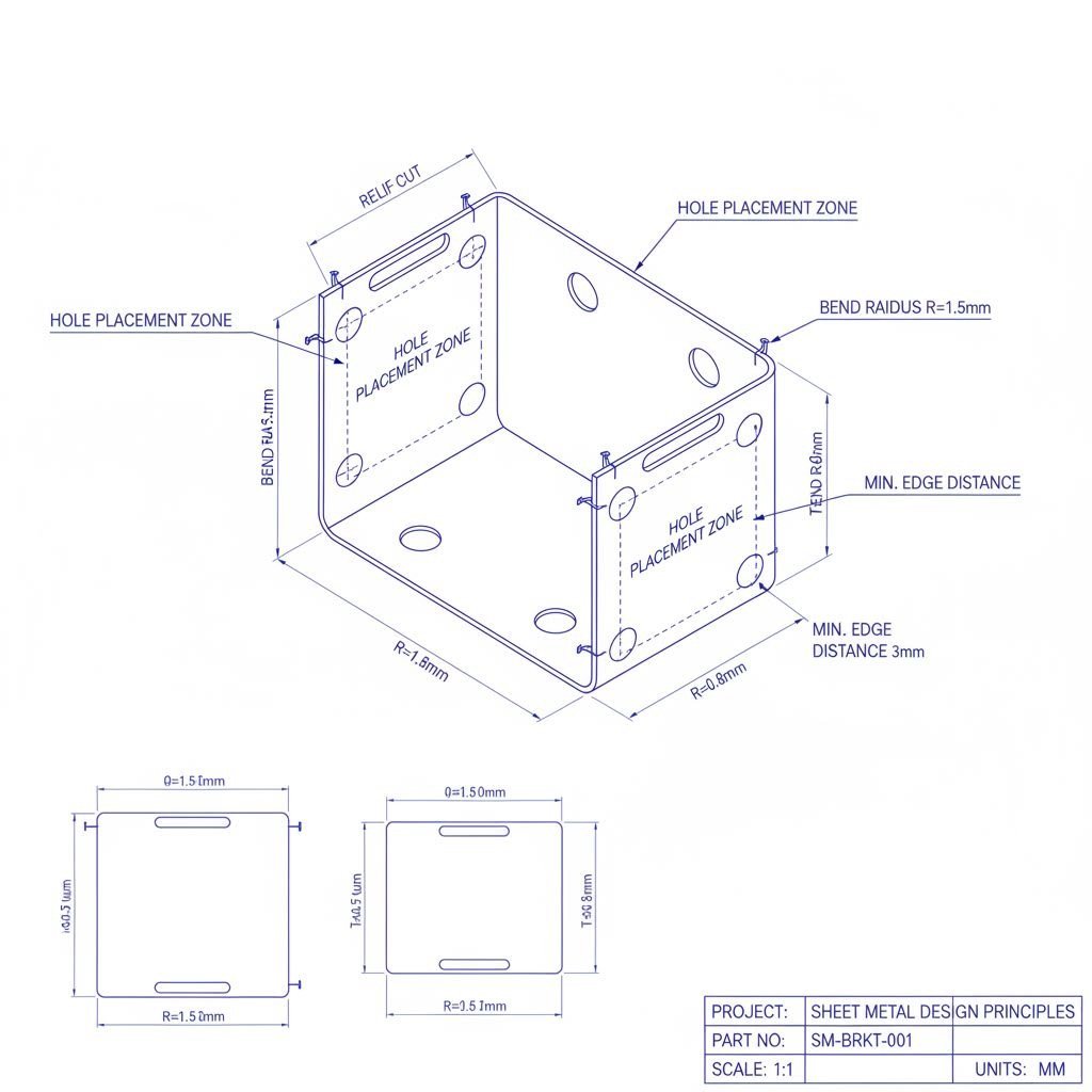
Bend Radius and Thickness Rules
The relationship between material thickness and minimum bend radius forms the foundation of sheet metal bending equipment compatibility. Ignore this relationship, and you'll encounter cracking, distortion, or outright forming failures.
Here's the core principle: the minimum inside bend radius should equal or exceed your material thickness. Designing a part from 2mm steel plate? Your inside bend radius should be at least 2mm. This 1:1 ratio gives the material room to stretch on the outside of the bend without exceeding its ductility limits.
But material matters. According to fabrication experts, aluminum requires more generous treatment—an inside bend radius no smaller than 2x the material thickness. That's double the standard ratio. Aluminum's tendency toward brittleness during forming makes this extra allowance essential.
What about those sharp corners your CAD software automatically creates? They're impossible to achieve. As industry professionals point out, your 3D modeling software might show perfectly sharp 90-degree angles, but the final part will always include a radius at least the size of your material's thickness. Design with this reality in mind from the start.
One more tip that saves significant tooling costs: use a uniform bend radius throughout your part. Every time the radius changes, metal forming machinery may require different tooling or additional setups. Three different radii means potentially three different dies and three separate operations. Standardizing on a single radius simplifies production and reduces per-part costs.
Hole Placement and Relief Cut Guidelines
Holes and bends don't mix well when positioned too close together. Understanding proper spacing prevents the distortion that ruins otherwise well-designed parts.
The critical rule: maintain a minimum distance of at least three times the material thickness plus the bend radius between hole edges and bend lines. Working with 2mm metal plate and a 2mm bend radius? Your holes should be at least 8mm away from any bend line. Position them closer, and the bending operation will stretch the material around the hole, turning round holes into elongated teardrops.
Relief cuts solve a different problem. When a bend terminates at a flat section of material, something has to give during forming. Without a relief cut, the material tears or deforms unpredictably. According to DFM guidelines, a bend relief is a small cut—either a slot or round hole—made at the end of the bend line that allows material to stretch without tearing.
Proper relief cut dimensions follow straightforward rules:
- Depth: Equal to or greater than the inside bend radius
- Width: At least equal to the material thickness
For hole spacing between features, the standard guideline recommends that the distance between two holes, or between a hole and the part's edge, should be at least two times the material thickness. This prevents stress zones from overlapping and causing warping or bulging.
And those u-channels you're designing? Remember this rule of thumb from metal sheet bending tools experts: a u-channel's throat must be as wide as or wider than its legs. Wide and short works. Tall and skinny creates problems that most press brakes simply cannot solve.
Avoiding Common Design Mistakes
Experience teaches hard lessons. Here are the design errors that cause the most forming failures—and how to prevent them:
- Ignoring grain direction: Sheet metal has a grain direction from the rolling process. Bends perpendicular to the grain are stronger and less prone to cracking than bends parallel to it. For brushed stainless steel plate, always call out grain direction on your drawings. According to fabrication specialists, failing to specify this creates ambiguity that leads to parts with brush marks running the wrong direction.
- Designing impossible flange lengths: Flanges need minimum length for tooling to grip properly. A safe rule: minimum flange length should be at least four times the material thickness. A 2mm thick part needs flanges at least 8mm long. Shorter flanges risk slippage and inconsistent bend angles.
- Creating too-tight u-channels: Most cnc sheet metal bending operations can achieve approximately 6-inch legs on u-channels. Need longer legs? You're likely looking at welding operations, which add cost and complexity.
- Forgetting tolerance stack-up: Each bend introduces potential variation. A bracket with six bends accumulates more dimensional uncertainty than one with two bends. When multiple formed parts must mate with each other, account for this cumulative variation in your tolerance allocations.
- Specifying too-small holes: The punch creating your holes needs sufficient strength to pierce the material without breaking. Standard recommendation: minimum hole diameter equals material thickness. For aluminum, increase that to 1.5x thickness because aluminum's heat absorption can cause deformation when small features are cut too closely together.
- Designing overly deep notches: Notches should be no deeper than 20 times the material thickness. Exceed this ratio and you risk tool breakage or material deformation during cutting operations.
Want to minimize tooling costs and setup time? Design with your fabricator's capabilities in mind. Standard tooling covers the vast majority of forming needs. Custom dies for unusual radii or specialty operations add significant expense. Ask your manufacturing partner about their standard tooling library before finalizing designs—a small radius adjustment might save thousands in tooling costs.
These guidelines bridge the gap between theoretical knowledge and successful production. Apply them consistently, and you'll create parts that flow through fabrication smoothly. The next section explores how emerging forming technologies compare to these established CNC methods, helping you evaluate which approaches best fit your specific production needs.
Emerging Technologies Versus Established Methods
You've mastered design guidelines for traditional CNC forming. But what if you could skip the tooling entirely? That's the promise of emerging digital sheet metal forming technologies that are reshaping prototyping and low-volume production. Understanding where these innovations excel—and where they fall short—helps you choose the right approach for each project.
The manufacturing landscape now includes options that didn't exist a decade ago. Some offer remarkable flexibility for custom work. Others remain better suited to high-volume efficiency. Let's examine what's actually available and where each technology delivers real value.
Digital and Incremental Forming Innovations
Digital Sheet Metal Forming (DSMF) represents one of the most significant departures from traditional methods. Also called incremental sheet forming or toolless stamping, this process uses a single-point tool that traces programmed paths across clamped sheet metal. Each pass deforms the material slightly, and accumulated passes gradually create complex three-dimensional geometries.
What makes digital sheet forming revolutionary? According to industry specialists, DSMF offers advantages including shorter lead times, faster production, elimination of expensive tooling and die manufacturing, and lower overall cost versus traditional parts stamping. Additionally, digital sheet forming has virtually no minimum order quantity, making it perfect for unique projects and rapid sheet metal prototyping.
The technology behind figur metal forming machines exemplifies this approach. These systems can form parts up to 57 inches by 39 inches in materials including cold rolled steel up to 2mm thick and 6061 aluminum up to 3.175mm thick. The accuracy typically falls between 0.5% to 2% of the largest dimension—acceptable for prototypes and many production applications, though less precise than traditional press brake operations.
Robo forming takes incremental forming in a different direction. Rather than dedicated machines, robo forming uses six-axis industrial robots fitted with hardened steel spherical tools. As engineering experts explain, the robot applies force incrementally against sheet material, creating plastic deformation millimeter by millimeter until the sheet stock is coaxed into the final shape.
The advantages of robotic incremental sheet forming include:
- Mass customization: The robot can form 100 different part geometries for the same cost and in the same time as 100 identical parts
- No springback: Because geometry is produced incrementally, there's no elastic recovery like you find with other sheet metal forming processes
- Low barrier to entry: With the right robot and programming expertise, this process can be set up relatively quickly
- Large working area: Unlike CNC machines limited by bed size, robots offer expansive working envelopes
What about 3d forming capabilities? Both DSMF and robo forming excel at creating complex curved surfaces that would require expensive matched dies with traditional methods. Think automotive body panels, aircraft skins, architectural features, or custom enclosures with smooth contours. The dieless nature of these processes means your CAD file translates directly to formed metal without weeks of die design and fabrication.
However, these technologies have limitations. Ideal parts for digital sheet forming are smooth, have less than 60 degrees of draft, and have no large flat areas. Steeper wall angles, convex geometry within the part, and large flat sections all increase forming difficulty. According to industry sources, parts with 70-90 degree walls or complex internal features push these technologies to their limits.
Established Methods for Production Volume
While emerging technologies capture attention, established CNC methods haven't stood still. Sheet metal forming machines using press brakes and panel benders continue to dominate production environments for good reasons.
Speed matters at scale. Robo forming and incremental processes move incrementally—by definition. A robot tracing paths millimeter by millimeter simply cannot match a press brake that forms each bend in seconds. For high-volume production, this speed difference translates directly to cost per part.
Precision remains superior. CNC press brakes routinely achieve angular tolerances of ±0.5° or better. While incremental forming typically delivers 0.5% to 2% accuracy based on part dimensions, traditional cnc metal forming provides tighter absolute tolerances that matter for precision assemblies.
Material thickness range extends further. Incremental forming technologies currently max out around 3mm for most materials. Traditional press brakes handle significantly thicker stock—heavy gauge steel plate that incremental tools simply cannot deform effectively.
Surface finish consistency improves. The incremental nature of digital forming can leave visible tool marks on surfaces. Parts requiring smooth, unmarked finishes often benefit from traditional forming where material contacts polished tooling rather than tracing spherical tools.
The economics flip at higher volumes. While digital forming eliminates die costs, the per-part time investment becomes prohibitive as quantities increase. A stamping die costing $50,000 might seem expensive until you're producing 100,000 parts—at which point the die cost per part becomes negligible while incremental forming time costs remain constant.
Choosing Technology Based on Your Needs
So which approach fits your project? The decision comes down to volume, complexity, timeline, and budget priorities.
| Factor | Digital/Incremental Forming | CNC Press Brake/Panel Bender | Progressive Die Stamping |
|---|---|---|---|
| Tooling Cost | Virtually none—only consumable end effectors | Moderate—standard dies with occasional custom tooling | High—custom progressive dies required |
| Production Speed (per part) | Slow—minutes to hours per part | Fast—seconds to minutes per bend | Fastest—multiple operations per press stroke |
| Part Complexity | Excellent for smooth 3D contours | Best for angular bends and flanges | Good for complex flat features with moderate forming |
| Ideal Volume Range | 1 to 100 parts | 10 to 10,000 parts | 10,000+ parts |
| Lead Time (first part) | Days—programming only | Days to weeks—setup and programming | Weeks to months—die design and fabrication |
| Dimensional Accuracy | ±0.5% to 2% of part dimensions | ±0.010" to ±0.030" typical | ±0.002" to ±0.005" achievable |
| Material Thickness Range | Up to ~3mm typically | Thin gauge to heavy plate | Thin to medium gauge |
Consider digital or incremental forming when:
- You need prototypes or very low quantities (under 100 parts)
- Part geometry includes smooth 3D contours rather than sharp bends
- Lead time matters more than per-part cost
- Design changes are likely and tooling investment would be risky
Stick with established CNC methods when:
- Production volumes justify programming and setup time
- Parts require angular bends rather than sculpted surfaces
- Tight dimensional tolerances are critical
- Material thickness exceeds incremental forming capabilities
The smartest manufacturers don't choose sides—they match technology to application. Prototype with digital forming to validate designs quickly, then transition to press brakes or stamping for production. This hybrid approach captures the benefits of both worlds while minimizing tooling risk during development.
With technology options clarified, your final decision involves selecting the right manufacturing partner. The next section covers evaluation criteria that help you identify fabrication partners with the capabilities, certifications, and support services your projects require.
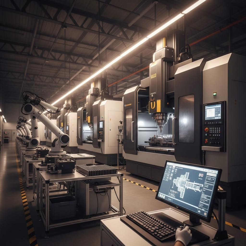
Selecting the Right CNC Forming Partner
You've learned the techniques, understood the tolerances, and designed parts optimized for manufacturing. Now comes the decision that determines whether all that knowledge translates into successful production: choosing the right fabrication partner. This isn't simply a purchasing decision—it's a strategic choice that affects quality, timeline, cost, and your ability to respond to market demands.
Whether you're searching for metal fabrication near me or evaluating steel fabricators across the country, the evaluation criteria remain consistent. The best fabrication shops near me aren't necessarily the closest ones—they're the ones whose capabilities align precisely with your requirements.
Certification and Quality Standards to Verify
Certifications provide baseline validation that a manufacturer operates documented, repeatable processes. But different industries demand different standards, and understanding which certifications matter for your application prevents costly misalignments.
- ISO 9001: The foundation of quality management systems. This certification demonstrates that a fabricator maintains documented processes, conducts regular audits, and commits to continuous improvement. Consider it the minimum requirement for any serious metal fabricators near me.
- IATF 16949: The automotive industry's enhanced quality standard. If you're producing chassis components, suspension parts, or structural assemblies for vehicles, this certification is non-negotiable. It adds automotive-specific requirements including production part approval processes, failure mode analysis, and stringent traceability.
- AS9100: The aerospace and defense standard that builds on ISO 9001 with additional requirements for safety, reliability, and configuration management. Aerospace brackets, enclosures, and structural components demand partners holding this certification.
- ITAR Registration: For defense-related work involving controlled technologies, ITAR (International Traffic in Arms Regulations) registration ensures your fabricator can legally handle sensitive designs and materials.
Beyond certifications, examine how potential partners approach quality internally. According to manufacturing experts, a partner with a strong quality focus will demonstrate continuous improvement goals beyond certification requirements, formal root cause analysis processes, investment in advanced inspection equipment, and transparent quality metrics they're willing to share.
Ask about specific quality goals and how they measure success. Request examples of how they've addressed quality issues in the past. Their answers reveal whether certifications represent genuine operational excellence or simply paperwork compliance.
Evaluating Prototyping and Production Capabilities
The ideal steel fabrication partner supports your product throughout its entire lifecycle—from initial concept through volume production. This requires evaluating capabilities across multiple dimensions.
Equipment capabilities should match your typical part requirements. Ask potential partners to map their capabilities against your most common parts. Do they have press brakes with sufficient tonnage for your material thicknesses? Can their equipment handle your maximum part sizes? Do they offer the forming techniques your designs require?
Material expertise matters more than equipment lists suggest. A shop may own capable machinery but lack experience with your specific alloys. If you're working with 316 stainless steel for marine applications or titanium for aerospace components, ask for examples of similar work. Material-specific knowledge about springback compensation, tooling selection, and surface protection prevents expensive learning curves on your projects.
Prototyping speed accelerates your entire product development cycle. When you can validate designs in days rather than weeks, you iterate faster and reach market sooner. Look for partners offering rapid turnaround—capabilities like 5-day prototyping from design file to finished parts compress development timelines dramatically.
For automotive applications requiring IATF 16949 certification, Shaoyi (Ningbo) Metal Technology exemplifies this approach, combining 5-day rapid prototyping with automated mass production capabilities for chassis, suspension, and structural components. Their comprehensive DFM support helps optimize designs before production begins.
Production capacity determines whether a partner can scale with your needs. A shop perfect for prototypes may struggle when you transition to thousands of parts monthly. Conversely, high-volume specialists may not prioritize your small initial orders. Evaluate partners on their flexibility to handle your current volumes while having capacity for growth.
Vertical integration simplifies your supply chain. Partners offering laser cutting, forming, welding, hardware installation, and finishing under one roof reduce coordination complexity and lead times. When evaluating metal fabricators near me, consider whether they handle secondary operations like powder coating services or anodizing in-house or through trusted partners. Integrated capabilities mean fewer handoffs and faster delivery.
The Value of DFM Support Services
Design for Manufacturing (DFM) support separates transactional suppliers from true manufacturing partners. According to industry specialists, designing for manufacturability means accounting for factors like bend relief, hole spacing, and material flow. Partners who engage during the design phase identify potential production issues early and adjust designs for cost-effective fabrication.
Strong DFM support delivers tangible benefits:
- Cost reduction: Identifying opportunities to simplify tooling, reduce setups, or eliminate unnecessary features before production begins
- Quality improvement: Flagging design elements that risk forming failures, surface defects, or dimensional instability
- Timeline acceleration: Preventing redesign cycles that delay production when manufacturability issues surface late
- Knowledge transfer: Building your team's understanding of forming constraints for future designs
When evaluating potential partners, ask how their engineering team interfaces with customers. Request examples of how they've improved designs or solved technical problems for similar projects. The best partners have engineers making up a significant portion of their workforce—demonstrating commitment to technical excellence rather than just production capability.
Quote turnaround expectations reveal operational efficiency and customer prioritization. If you're waiting weeks for a simple quote, imagine the delays during actual production. Fast response times—such as 12-hour quote turnaround—indicate streamlined processes and genuine interest in your business. When searching for sheet metal bending services near me, responsiveness during the quoting phase often predicts responsiveness throughout your project.
Ask about their typical quote-to-production timeline. Understand what information they need upfront to provide accurate quotes. Partners who ask detailed questions about tolerances, finishes, and quantities demonstrate thoroughness that carries through to production.
The right CNC forming partner becomes an extension of your engineering team. They catch design issues before they become production problems, suggest improvements you hadn't considered, and deliver parts that meet specifications consistently. Whether you're producing prototypes for validation or ramping to full production, that partnership makes the difference between manufacturing headaches and manufacturing success.
Frequently Asked Questions About CNC Sheet Metal Forming
1. What is digital sheet metal forming and how does it differ from traditional CNC methods?
Digital Sheet Metal Forming (DSMF) uses a single-point tool that traces programmed paths across clamped sheet metal, gradually creating complex 3D shapes without matched dies. Unlike traditional CNC press brakes that form bends in single operations, DSMF eliminates expensive tooling costs and has virtually no minimum order quantity. However, traditional methods remain faster for high volumes and achieve tighter tolerances of ±0.5° compared to DSMF's 0.5-2% accuracy. DSMF excels at prototyping and low-volume production under 100 parts, while press brakes and stamping dominate medium-to-high volume manufacturing.
2. How much does a CNC sheet metal forming machine cost?
CNC sheet metal forming machine prices vary significantly based on type and capability. Entry-level CNC press brakes start around $30,000-$50,000, while high-end panel benders and advanced press brakes with automatic tool changers can exceed $500,000. Digital sheet forming machines like the Figur G15 represent premium investments. Beyond equipment costs, factor in programming software, training, installation, and maintenance. The ROI depends on production volume—higher initial investment in CNC equipment delivers lower per-part costs at scale compared to manual methods.
3. What tolerances can CNC sheet metal forming achieve?
Tolerance capabilities vary by forming method. CNC press brakes typically achieve ±0.5° to ±1° angular tolerance and ±0.010" to ±0.030" dimensional accuracy. Panel benders often deliver tighter results at ±0.25° angular tolerance. Progressive die stamping achieves the tightest tolerances at ±0.002" to ±0.005" for critical features. Incremental forming methods deliver ±0.020" to ±0.040" for complex contours. Material properties, part complexity, and equipment quality all influence achievable precision. For IATF 16949-certified automotive components, manufacturers like Shaoyi Metal Technology maintain these tight tolerances through automated production systems.
4. What materials work best for CNC sheet metal forming?
Aluminum alloys (5052, 6061, 3003) offer excellent formability and lightweight properties but exhibit three times the springback of steel. Mild steel provides cost-effective, predictable forming behavior ideal for structural applications. Stainless steel delivers corrosion resistance but requires greater forming forces and exhibits significant work hardening—316 stainless is particularly challenging. Copper forms easily with high ductility, while brass offers good formability with attractive appearance. Material thickness typically ranges from 26-gauge (0.018") for electronics enclosures to heavy plate (1/4"+) for structural components.
5. How do I choose the right CNC forming partner for automotive applications?
For automotive applications, prioritize IATF 16949 certification—this automotive-specific quality standard ensures documented processes, production part approval, and stringent traceability. Evaluate prototyping speed (5-day turnaround accelerates development), DFM support capabilities, and quote responsiveness (12-hour turnaround indicates operational efficiency). Assess equipment capacity matching your material thicknesses and part sizes. Shaoyi (Ningbo) Metal Technology exemplifies these criteria, offering rapid prototyping to automated mass production for chassis, suspension, and structural components with comprehensive DFM support at shao-yi.com/auto-stamping-parts/.