 Small batches, high standards. Our rapid prototyping service makes validation faster and easier —

Automotive Prototype Stamping Methods: Soft vs. Hard Tooling Guide
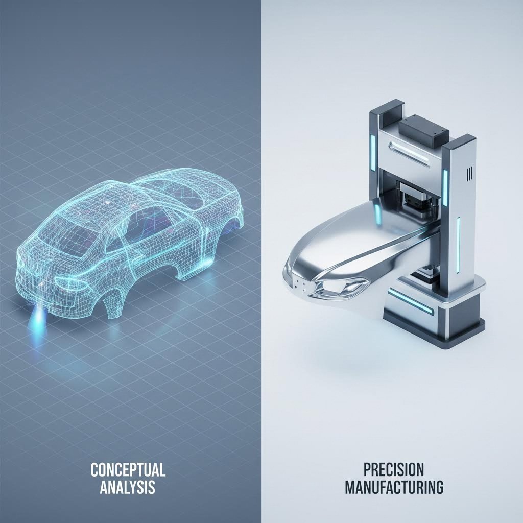
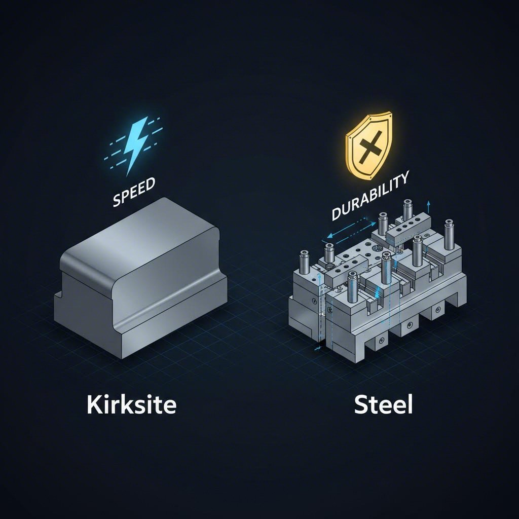
<h2>TL;DR</h2><p>Automotive prototype stamping methods bridge the critical gap between digital CAD designs and mass production. Engineers primarily use <strong>Soft Tooling</strong> (utilizing Kirksite or aluminum dies) to validate complex geometries like deep-drawn fenders or hoods at a fraction of the cost of hardened production steel. for simpler structural components like brackets, <strong>Hybrid Fabrication</strong> combines laser cutting or wire EDM with press brake forming to eliminate tooling costs entirely. While Soft Tooling offers the highest fidelity to production variables (springback, thinning), Hybrid methods provide the fastest turnaround (1–3 days). Choosing the right method depends on your validation goals: functional crash testing requires the material properties of stamped parts, whereas fit-checks may only need dimensional accuracy.</p><h2>Method 1: Soft Tooling (The Industry Standard)</h2><p>Soft tooling remains the dominant method for validating automotive body-in-white (BIW) structures and complex chassis components. Unlike production dies made from hardened tool steels (like D2 or carbide), soft tools are machined from softer, easier-to-cut materials such as <strong>Kirksite</strong> (a zinc-aluminum alloy), mild steel, or aluminum. This approach allows manufacturers to produce functional metal parts that exhibit nearly identical physical characteristics to mass-produced versions, including flow lines, thinning, and work hardening.</p><p>The primary advantage of soft tooling is speed and cost efficiency. Because these materials are softer, they can be machined 30% to 50% faster than hardened steel, reducing lead times from months to weeks. This allows engineers to physically test the <em>drawability</em> of a design—identifying potential splitting or wrinkling issues—long before committing to expensive Class A progressive dies. However, the trade-off is durability. A Kirksite die may only last for 50 to 500 shots before degrading, making it strictly a validation or bridge-production solution.</p><p>Soft tooling is particularly indispensable for <strong>deep draw stamping</strong>. Simple forming methods cannot replicate the complex material flow required for parts like oil pans or door inners. Soft tooling mimics the binder pressure and draw bead functionality of a production die, providing data that is critical for finalizing the production tool design.</p><h2>Method 2: Laser Cutting & Press Brake (The No-Tooling Hybrid)</h2><p>For brackets, reinforcements, and structural members that do not require complex 3D contouring, the hybrid approach of laser cutting (or Wire EDM) followed by press brake forming is the most efficient path. This method effectively removes the "blanking die" from the equation. Instead of building a tool to cut the flat pattern, the blank is cut directly from the coil or sheet using a high-precision laser or waterjet.</p><p>Once the blank is cut, CNC press brakes form the bends. This process is ideal for "2.5D" parts where the deformation occurs along linear axes. Because there is zero investment in custom tooling, the initial cost is significantly lower, and the first article can often be delivered within 24 to 48 hours. Advanced providers integrate <strong>Wire EDM</strong> for extremely tight tolerances on internal features that lasers might distort thermally.</p><p>However, this method has limitations. It cannot produce the "wiped" flanges or complex curvatures found in exterior skin panels. It also treats bending as a separate operation from cutting, which differs from the continuous process of a progressive die. Engineers must account for these process differences when evaluating springback results, as the stress distribution in a brake-formed part differs from one formed in a stamp-through die.</p><h2>Method 3: Rapid Tooling & Innovative Technologies</h2><p>The frontier of automotive prototype stamping is moving toward <strong>Rapid Tooling</strong> technologies that further compress lead times. This includes 3D-printed dies (using high-strength polymers or sintered metal composites) and Incremental Sheet Forming (ISF).</p><ul><li><strong>3D Printed Dies:</strong> For extremely low volumes (e.g., 10–50 parts), composite dies can withstand the tonnage required to form light-gauge aluminum or steel. This eliminates CNC machining entirely, allowing a die to be printed overnight. While surface finish and tool life are lower, it is often sufficient for fit-up testing.</li><li><strong>Hot Stamping Prototypes:</strong> As automotive safety standards demand higher tensile strengths, prototyping <strong>boron-based steels</strong> becomes critical. Specialized prototype shops now offer hot stamping capabilities, heating blanks to over 900°C before quenching them in a water-cooled die. This process creates lightweight, ultra-high-strength parts (like A-pillars) that cold forming cannot achieve.</li></ul><h2>Critical Analysis: Soft Tooling vs. Hard Tooling</h2><p>The decision between investing in soft tooling or moving straight to hard tooling is a major procurement milestone. Soft tooling acts as a risk mitigation step, whereas hard tooling is a capital commitment to volume production. The table below outlines the strategic differences:</p><table><thead><tr><th>Feature</th><th>Soft Tooling (Kirksite/Alum)</th><th>Hard Tooling (D2/Carbide)</th><th>Hybrid (Laser + Brake)</th></tr></thead><tbody><tr><td><strong>Primary Use</strong></td><td>Validation, Deep Draw, Complex Surfaces</td><td>Mass Production (>50k parts)</td><td>Simple Brackets, Linear Bends</td></tr><tr><td><strong>Cost Factor</strong></td><td>Low (10-20% of Hard Tool)</td><td>High (Capital Expenditure)</td><td>Lowest (Zero Tooling)</td></tr><tr><td><strong>Lead Time</strong></td><td>2–6 Weeks</td><td>12–24 Weeks</td><td>1–3 Days</td></tr><tr><td><strong>Tool Life</strong></td><td>50 – 1,000 Shots</td><td>Millions of Shots</td><td>N/A (Process Dependent)</td></tr><tr><td><strong>Fidelity</strong></td><td>High (Production intent)</td><td>Exact (Production standard)</td><td>Medium (Different stress profile)</td></tr></tbody></table><p>Most automotive programs utilize soft tooling for the "Beta" build phase, allowing engineers to freeze the design before cutting hard steel. Skipping this step often leads to costly engineering change orders (ECOs) if the hard tool requires modification later.</p><h2>Validation & Simulation: The "Step Zero"</h2><p>Before any metal is cut, <strong>digital stamping simulation</strong> (using software like AutoForm or Siemens NX) serves as the virtual prototype. This step is non-negotiable in modern automotive engineering. Simulation predicts critical failure modes such as splitting, excessive thinning, and wrinkling by analyzing the material flow virtually.</p><p>Digital validation allows engineers to optimize the blank shape and binder pressure settings <em>in silico</em>. By solving these issues digitally, the physical soft tool works correctly on the first or second try, rather than the tenth. This integration of virtual simulation with physical prototyping significantly accelerates the development cycle.</p><h2>Transitioning to Mass Production</h2><p>The ultimate goal of any prototype method is to pave the way for successful volume manufacturing. Data gathered during the soft tooling phase—such as springback compensation values and blank development—is directly fed into the design of the progressive die.</p><p>For programs requiring a seamless scale-up, partnering with a manufacturer capable of handling the entire lifecycle is advantageous. <a href="https://www.shao-yi.com/auto-stamping-parts/">Shaoyi Metal Technology</a> specializes in this transition, offering IATF 16949-certified stamping solutions that bridge the gap from rapid prototyping to high-volume production. Their capabilities, including presses up to 600 tons, allow for the validation of critical components like control arms and subframes under production-grade conditions, ensuring that the 50th prototype performs identically to the millionth production part.</p><section><h2>Strategic Prototyping Decisions</h2><p>Selecting the correct automotive prototype stamping method is a balance of engineering fidelity, budget, and timeline. While laser cutting and hybrid methods offer speed for simple parts, soft tooling remains the engineering standard for validating complex, safety-critical geometries. By leveraging simulation and choosing the appropriate tooling strategy early in the design phase, automotive engineers can de-risk their programs and ensure a smooth transition to the assembly line.</p></section><section><h2>Frequently Asked Questions</h2><h3>1. What is the difference between prototype stamping and progressive die stamping?</h3><p>Prototype stamping typically uses single-stage soft tooling or laser cutting to produce parts one at a time, focusing on low cost and design validation. Progressive die stamping is a mass-production method where a single coil of metal moves through multiple stations in a hardened steel die, producing finished parts at high speed with every stroke of the press.</p><h3>2. Can prototype stamped parts be used for crash testing?</h3><p>Yes, provided they are made using <strong>soft tooling</strong> and the correct production-intent material. Soft tooling allows the metal to flow and work-harden similarly to production tools, giving the part the structural integrity required for valid crash test data. Parts made via simple bending (hybrid methods) may not have the same work-hardening characteristics in complex areas.</p><h3>3. How long does it take to make a soft tool for stamping?</h3><p>Soft tooling lead times typically range from <strong>2 to 6 weeks</strong>, depending on part complexity. This is significantly faster than hardened production tooling, which often requires 12 to 20 weeks. Simple laser-cut and press brake parts can often be completed in just a few days.</p></section>