 Small batches, high standards. Our rapid prototyping service makes validation faster and easier —

7 Steps To Master The Upset Forging Process For Axles That Last
Why Upset Forging Delivers Superior Axle Performance
When you're manufacturing axles that must endure thousands of miles under heavy loads, choosing the right metal forming process isn't just a preference—it's a necessity. Axles represent some of the most demanding load-bearing components in automotive, agricultural, and heavy equipment applications. They experience constant torsional stress, bending forces, and impact loads that would cause lesser components to fail catastrophically. So, what makes certain axles outlast others by decades? The answer often lies in how they're forged.
Why Axles Demand Upset Forging Excellence
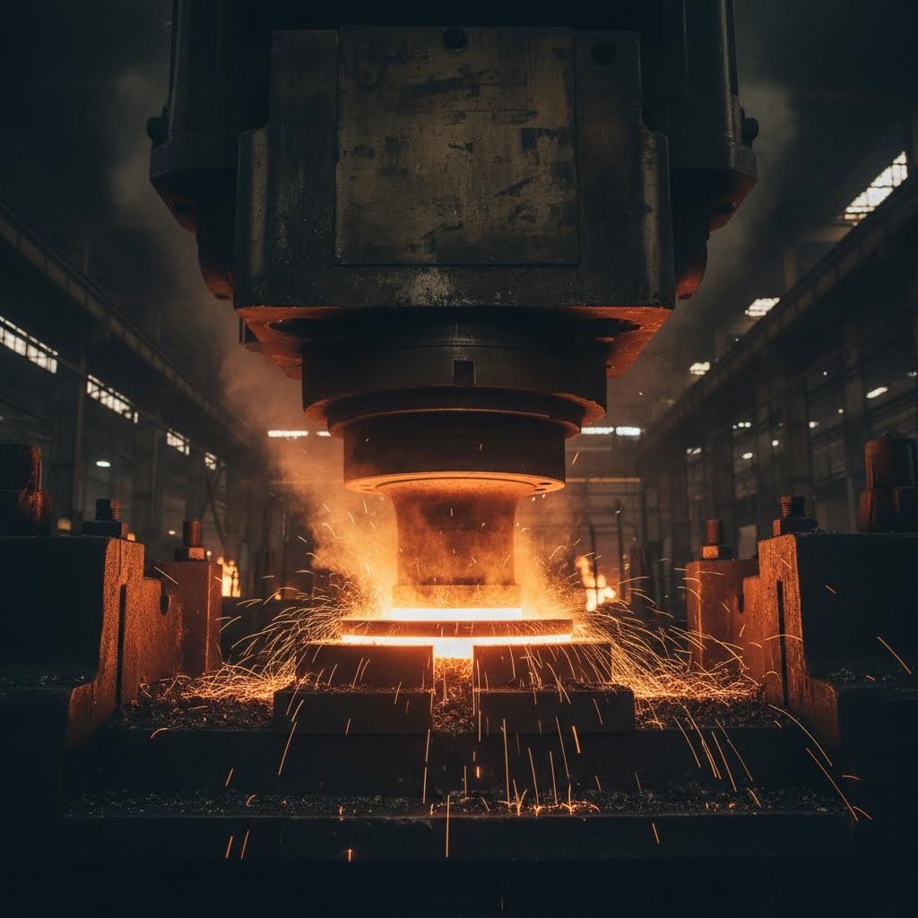
Imagine squishing a piece of clay between your palms, making it wider but shorter. The upset forging process works on a similar principle—but with intense heat and precisely controlled pressure applied to metal. In this specialized technique, compressive force is applied to the heated end of a metal bar, increasing its diameter while reducing its length. This controlled deformation is exactly what axle ends require to form robust flanges, mounting surfaces, and connection points.
Axle shafts undergo extreme stress during operation. According to industry analysis, properly upset-forged parts can increase the lifespan of such components by up to 30% compared to alternative manufacturing methods. For axle applications specifically, this longevity advantage translates directly into reduced maintenance costs, improved safety, and enhanced vehicle reliability.
The Strength Advantage of Upset Formed Axles
What makes this process so effective for axles? When metal is upset forged, something remarkable happens at the microstructural level. The grain flow—the internal fiber-like structure of the metal—realigns to follow the contour of the finished part. For axles, this means the grain structure flows continuously through high-stress areas like flanges and end fittings, creating natural reinforcement exactly where it's needed most.
This guide walks you through the complete axle upset forging workflow, from raw material selection to finished component inspection. Whether you're a manufacturing engineer evaluating process options or a production manager seeking to optimize existing operations, you'll find practical, step-by-step guidance for each phase of production.
Understanding the Upset Forging Fundamentals
How does this method compare to alternatives? Let's break it down. Open die forging shapes metal between flat dies without fully enclosing it—excellent for large, simple shapes but lacking the precision axle ends demand. Closed die forging uses shaped cavities to form parts but can be less material-efficient and more costly for the specific geometry of axle flanges. Roll forging efficiently creates elongated sections but struggles with the varying cross-sections that axle applications require.
Upset forging stands apart because it's specifically designed to increase diameter at targeted locations—precisely what axle manufacturing demands. The key benefits that make it uniquely suited for axle production include:
- Enhanced grain flow alignment: The compression process forces metal grains to flow parallel to the part contours, dramatically improving fatigue resistance and impact strength in critical stress zones
- Superior material efficiency: With minimal waste during the forming process, material savings can reach up to 15% compared to other forging methods, reducing both costs and environmental impact
- Optimized mechanical properties: The controlled deformation refines the metal's grain structure, delivering higher tensile strength and toughness specifically in the load-bearing sections of the axle
- Dimensional accuracy: Tight tolerances are achievable even in complex axle end geometries, reducing secondary machining requirements
- Customization flexibility: The process readily accommodates varying flange sizes, mounting configurations, and end-fitting designs across different axle types
Ready to master each step of this essential manufacturing process? The following sections provide detailed guidance through material selection, heating protocols, die setup, the forging operation itself, post-processing, quality control, and supplier partnership—everything you need to produce axles built to last.
Step 1 Selecting and Preparing Your Axle Stock Material
Before any heat is applied or dies are positioned, success in the upset forging process begins with one fundamental decision: what material will you use? Choosing the wrong steel grade—or failing to properly prepare your stock—can undermine even the most precisely controlled forging operation. Think of material selection as laying the foundation for a building. No matter how skilled the construction crew, a weak foundation guarantees problems down the road.
Selecting the Right Steel Grade for Your Axle Application
Different axle types face dramatically different operating conditions, and your material choice must reflect these demands. Drive axles transmit torque from the drivetrain to the wheels, enduring constant rotational stress and occasional impact loads. Steering axles must combine strength with precise dimensional stability. Trailer axles carry heavy static loads while resisting fatigue from road vibrations over millions of cycles.
So, which steel grades deliver the performance each application demands? The answer depends on balancing strength, toughness, fatigue resistance, and cost. Here's how common materials align with specific axle requirements:
| Steel Grade | Key Properties | Best Suited For | Typical Applications |
|---|---|---|---|
| AISI 4340 | High tensile strength, excellent fatigue resistance, good toughness | Drive axles, high-performance applications | Automotive powertrains, heavy-duty trucks, off-road vehicles |
| AISI 4140 | Good strength-to-cost ratio, versatile heat treatment response | General-purpose drive and steering axles | Commercial vehicles, agricultural equipment |
| AISI 1045 | Moderate strength, good machinability, economical | Trailer axles, lighter-duty applications | Utility trailers, light industrial equipment |
| AISI 4130 | Excellent weldability, good strength, lightweight potential | Steering axles, specialty applications | Aerospace ground support, racing applications |
According to industry specifications, 4340 alloy steel remains a preferred choice for demanding drive shaft and axle applications, featuring chemical composition ranges of 0.38-0.43% carbon, 1.65-2.0% nickel, and 0.70-0.90% chromium. These alloying elements work together to deliver the exceptional mechanical properties that high-stress axle components require.
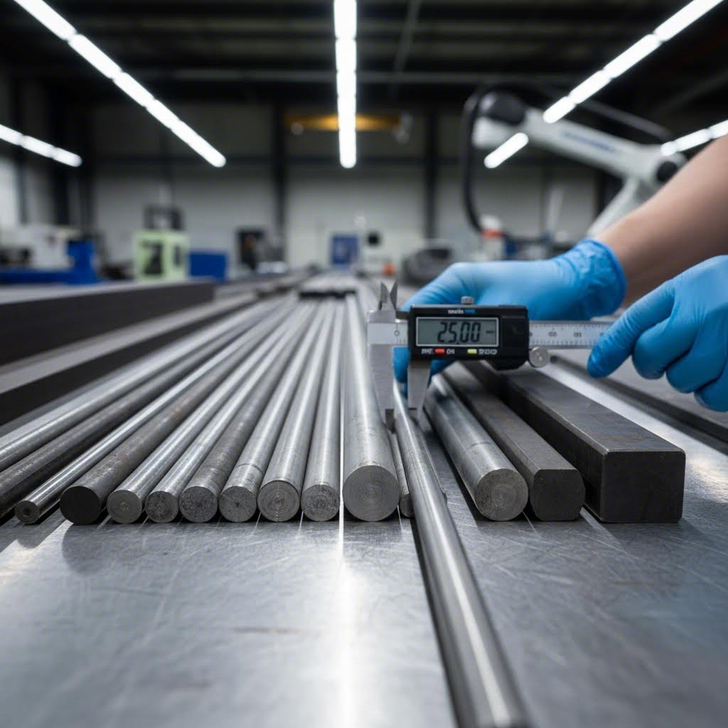
Stock Preparation Checklist Before Forging
Once you've selected your steel grade, proper stock preparation becomes critical. The benefits of forging can only be realized when you start with quality raw material that's been correctly sized and inspected. What does thorough preparation look like in practice?
- Cutting to precise length: Calculate the exact billet weight required for your final axle component, accounting for flash and trim allowances—typically 5-10% beyond net weight
- Surface inspection: Examine the stock for surface defects including cracks, seams, laps, or scale that could propagate during the upsetting in forging operations
- Dimensional verification: Confirm diameter and length measurements fall within specified tolerances, as even small variations affect material flow during upset
- Material traceability: Document heat numbers and mill certifications to maintain quality records throughout production
- End preparation: Ensure cut ends are square and free of burrs that could cause uneven heating or material flow
Any imperfections in the raw material can propagate during the forging process, potentially compromising the structural integrity of your finished axle. Taking time for thorough inspection now prevents costly rejections and safety concerns later.
Material Properties That Impact Axle Performance
Understanding what's forging at the metallurgical level helps explain why material selection matters so much. When you heat steel to forging temperature and apply compressive force, you're not just reshaping metal—you're refining its internal grain structure. The steel grade you choose determines how effectively this refinement occurs.
Several material properties directly influence both the upset forging process parameters and the finished axle's performance:
- Carbon content: Higher carbon levels increase hardness and strength but reduce ductility during forging, requiring more careful temperature control
- Alloying elements: Nickel improves toughness, chromium enhances hardenability, and molybdenum increases high-temperature strength—each affecting both forging behavior and final properties
- Grain size: Finer grain structures deliver better fatigue resistance, and proper forging promotes grain refinement when executed correctly
- Inclusion content: Non-metallic inclusions can act as stress concentrators, making material cleanliness essential for load-bearing axle components
For critical applications, material testing should verify mechanical properties before forging begins. Industry standards typically require yield strength, tensile strength, elongation, and impact testing results, along with metallographic examination for grain size and inclusion content. These quality gates ensure your raw material can deliver the performance your axles demand.
With your material selected and stock properly prepared, you're ready to move into the heating phase—where precise temperature control transforms rigid steel into a workable material ready for upsetting.
Step 2 Heating the Axle Blank to Forging Temperature
You've selected your steel grade and prepared your stock—now comes a step that can make or break your entire upset forging process. Heating the axle blank might seem straightforward, but achieving the precise temperature window while maintaining uniform heat distribution throughout the workpiece requires both technical knowledge and careful monitoring. Get this phase wrong, and you'll struggle with incomplete material flow, increased die wear, or compromised grain structure in your finished axle.
Achieving Optimal Forging Temperature for Axle Steel
What temperature should you target? The answer depends directly on your material grade. According to carbon steel forging specifications, the forging temperature typically ranges from 1,000°C to 1,200°C (1,800°F to 2,200°F), with specific targets varying by carbon content and alloying elements.
Here's how common axle materials differ in their temperature requirements:
- Low and medium carbon steels (1045, 1040): These grades forge optimally between 1,100°C and 1,200°C (2,000°F to 2,200°F), offering a relatively wide working range
- High carbon steels: Require slightly lower temperatures, typically 1,000°C to 1,200°C (1,800°F to 2,200°F), to prevent grain coarsening and decarburization
- Alloy steels (4140, 4340): Generally forge within the 1,100°C to 1,200°C range, though specific alloying elements may require adjustments to the upper or lower limits
Why does staying within this window matter so much? Underheating leaves the steel too rigid for proper material flow during the upset operation—you'll see incomplete die fill and potential cracking. Overheating weakens the metal's grain boundaries, causes excessive scale formation, and can lead to a condition called "burning" where grain boundary oxidation permanently damages the steel's integrity.
Heating Methods and Their Impact on Grain Structure
Two primary heating methods dominate axle forging operations: induction heating and gas-fired furnaces. Each offers distinct advantages depending on your production requirements.
Induction Heating
Imagine generating heat directly within the metal itself rather than transferring it from an external source. That's exactly how induction heating works—an alternating current flowing through a surrounding coil creates a magnetic field that induces electric currents within the steel billet, causing rapid internal heating. According to induction forging research, this method typically heats metal to forging temperature between 1,100°C and 1,200°C (2,010°F to 2,190°F) with several key advantages:
- Faster heating cycles that significantly boost productivity
- Precise temperature control preventing overheating damage
- Uniform heating throughout the workpiece for consistent forgings
- Reduced scale formation compared to furnace methods
- Improved surface finish on forged parts
- Greater energy efficiency since heat generates directly within the metal
For upset forging examples where only the axle end requires heating, induction systems excel at localizing heat precisely where deformation will occur—saving energy and reducing scale on portions that won't be forged.
Gas-Fired Furnaces
Traditional gas furnaces remain widely used for batch heating of axle blanks, particularly when entire billets require uniform heating or when production volumes justify continuous furnace operations. These systems heat metal through convection and radiation from burner flames and hot furnace walls. While heating rates are slower than induction, gas furnaces offer lower capital costs and work effectively for larger workpieces where induction coil sizing becomes impractical.
Electric forging furnaces provide another alternative, offering cleaner operation and precise temperature control, though operating costs may be higher depending on local energy prices.
Temperature Monitoring and Control Best Practices
How do you know when your axle blank has reached the proper forging temperature? Experienced operators can assess approximate temperature by the steel's color—bright cherry red indicates roughly 850°C, while yellow-orange suggests temperatures approaching 1,100°C. However, visual assessment alone isn't sufficient for consistent quality.
Modern upset forging operations rely on instrumentation for precise control:
- Optical pyrometers: Non-contact temperature measurement ideal for monitoring workpiece temperature as it exits the furnace or during induction heating
- Thermocouples: Direct contact measurement used in furnace control systems and for calibration verification
- Infrared cameras: Provide thermal mapping across the workpiece surface, identifying cold spots or overheated areas before forging begins
Heating time considerations vary based on stock diameter. Larger diameter billets require longer soak times to ensure the core reaches forging temperature—a 100mm diameter bar needs substantially more time than a 50mm bar to achieve uniform through-thickness heating. Rushing this phase creates a temperature gradient where the surface is properly heated but the core remains too cold for optimal upset forging operation.
Uniform heat distribution directly affects your final axle quality. Temperature variations across the heated section cause uneven material flow during upsetting, resulting in asymmetric flanges, internal voids, or laps where metal folds over itself. The goal is heating the entire deformation zone to within ±20°C of your target temperature before transferring to the forging press.
With your axle blank heated uniformly to the optimal forging temperature, the next critical step involves positioning this workpiece precisely within properly prepared dies—a setup phase that determines whether your upset operation will produce the exact flange geometry your application demands.

Step 3 Setting Up Dies and Positioning the Workpiece
Your axle blank is heated to the perfect temperature, glowing with that characteristic orange-yellow hue. But before any metal flows, you face a step that separates professional-grade axle production from inconsistent results: die setup and workpiece positioning. Think of this phase as setting the stage before a performance—every element must be precisely arranged, or the entire production suffers. Even experienced operators recognize that proper forging die setup directly determines whether the upset operation produces dimensionally accurate flanges or scrap material.
Die Design Considerations for Axle Flanges and Ends
What makes axle forging dies different from general-purpose upset tooling? The answer lies in the unique geometry these components demand. Axle ends require specific flange profiles, mounting surfaces, and connection features that must form completely during a single upset stroke—or at most, a carefully controlled sequence of strokes. Dies must be engineered to guide material flow precisely where it's needed while preventing defects like cold shuts or incomplete fill.
According to forging process research, precision in die design is paramount, as it directly influences the shape, dimensions, and properties of the forged part. Engineers use advanced CAD software to create precise 3D models of the die, ensuring that every contour and surface is optimized for the forging operation.
Die geometry varies significantly across axle types:
- Drive axle dies: Feature deeper cavities to accommodate larger flange diameters and thicker cross-sections required for torque transmission
- Steering axle dies: Prioritize dimensional precision with tighter tolerances for proper suspension geometry alignment
- Trailer axle dies: Often incorporate simpler flange profiles but must handle the consistent high-volume production these applications demand
Die material selection proves equally critical. Tool steels such as H13 and D2 are commonly used because they offer excellent hardness, toughness, and heat resistance. These materials must withstand the extreme pressures and temperatures of repeated forging cycles without losing dimensional accuracy. The die cavity surface finish also matters—smoother surfaces promote better material flow and reduce friction, while also producing forged parts with superior surface quality.
Proper Workpiece Gripping and Alignment Techniques
Sounds complex? Here's the essential concept: during upset forging, only a portion of the axle blank gets deformed while the remainder must be held absolutely stationary. The gripping mechanism—typically integrated into the die assembly—clamps the unheated section of the workpiece firmly in place while the heated end undergoes compression.
When you position the axle blank, alignment becomes everything. Even slight misalignment between the workpiece axis and the die cavity centerline causes asymmetric material flow. The result? Flanges that are thicker on one side, off-center mounting holes, or internal stress concentrations that compromise fatigue life. You'll notice that experienced operators spend considerable time verifying alignment before initiating the upset stroke.
Critical positioning factors include:
- Axial alignment: The workpiece centerline must coincide precisely with the die cavity centerline to ensure symmetric material flow during upsetting
- Insertion depth: The heated section must extend the correct distance beyond the gripping dies—too little material and the flange won't form completely; too much and buckling can occur
- Rotational orientation: For axles with non-symmetric features, proper rotational positioning ensures mounting holes and keyways align with final machining requirements
- Grip pressure: Sufficient clamping force prevents workpiece movement during forging while avoiding marks or deformation in the gripped section
Die preheating deserves special attention for axle upset forging operations. Cold dies rapidly extract heat from the workpiece surface, causing temperature gradients that lead to uneven deformation and potential surface cracking. Preheating dies to 150-300°C (300-570°F) before production begins reduces thermal shock and promotes consistent material flow throughout each forging cycle.
Die Maintenance for Consistent Axle Quality
Imagine running hundreds of axle blanks through your upset forging operation. Each cycle subjects the dies to tremendous mechanical and thermal stress. Without proper maintenance protocols, die wear gradually degrades your part quality—tolerances drift, surface finish deteriorates, and eventually, defects become unacceptable.
According to manufacturing research, proper material selection and treatment ensure that dies can withstand the rigors of the forging process while maintaining dimensional accuracy and surface finish over extended production runs. Surface treatments and coatings can be applied to enhance die life and improve the quality of forged parts.
What does an effective die maintenance program include? Regular inspection between production runs catches wear patterns before they affect part quality. Look for erosion in high-contact areas, heat checking (fine surface cracks from thermal cycling), and any buildup of scale or oxide that could transfer to forged surfaces. Polishing worn surfaces and applying fresh lubricant before each shift maintains consistent friction conditions.
Before beginning any upset operation on axle components, complete this setup verification checklist:
- Visual die inspection: Check for cracks, erosion, or damage that could affect part geometry or cause catastrophic failure
- Die temperature verification: Confirm preheating has brought dies to the specified temperature range using surface thermometers or thermal imaging
- Alignment confirmation: Verify die halves close concentrically and that gripping surfaces align properly with the forging cavity
- Lubrication application: Apply appropriate die lubricant to reduce friction and promote material flow while preventing workpiece adhesion
- Stroke adjustment: Set press stroke length to achieve the required upset ratio without over-compressing the workpiece
- Safety interlocks: Verify all guards are in place and emergency stops function correctly before production begins
- Test piece evaluation: Run a sample forging to verify setup before committing to full production—inspect dimensions and surface quality against specifications
With dies properly installed, preheated, and verified—and your heated axle blank precisely positioned—you're ready for the core of the entire process: executing the upset forging operation that transforms your cylindrical stock into a robust axle end with the exact flange geometry your application demands.
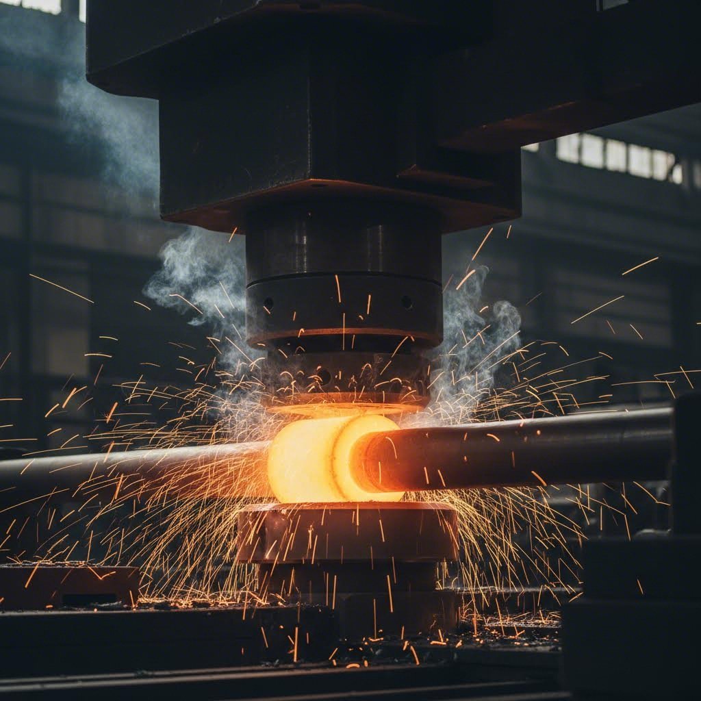
Step 4 Executing the Upset Forging Operation
This is the moment everything has been building toward. Your material is selected and prepared, your axle blank is heated to the precise temperature, and your dies are positioned and verified. Now comes the heart of the axle forging process—the actual metal upsetting technique that transforms a simple cylindrical bar into a robust axle end with the exact flange geometry your application demands. Get this step right, and you'll produce axles that outlast the competition. Miss the mark, and you're looking at scrapped parts and wasted resources.
Executing the Upset Stroke for Optimal Material Flow
What actually happens when that heading tool contacts your heated axle blank? According to The Open University's manufacturing research, a heading tool or ram is positioned perpendicular to the cross-sectioned end face of the rod gripped in a die. On application of pressure, the length of the rod is reduced and the diameter is increased—this is the essence of upsetting.
Imagine squeezing a tube of toothpaste from the end while blocking the opening. The material has nowhere to go but outward. In upset forging operation, that "outward" movement is precisely controlled by the die cavity, forcing the heated metal to flow into the exact shape of your axle flange or mounting surface.
The mechanics work like this: compressive force applied axially causes the heated metal to plastically deform. Because the material is constrained by the gripping dies on one side and the heading tool on the other, it expands radially into the die cavity. The result is a significant increase in cross-sectional area at the upset location—exactly what axle ends require for proper flange formation.
Here's the sequential breakdown of executing a successful upset stroke:
- Initial contact: The heading tool advances until it makes full contact with the heated end face of the axle blank—ensure contact is uniform across the entire surface
- Compression initiation: Apply forging pressure gradually to begin material displacement, monitoring for any signs of buckling or misalignment
- Material flow phase: As pressure increases, the heated metal begins flowing radially outward, filling the die cavity progressively from center to periphery
- Cavity fill completion: Continue the stroke until material completely fills the die cavity, including any flange details, mounting surfaces, or connection features
- Dwell period: Maintain pressure briefly at full stroke to ensure complete die fill and allow any residual material movement to stabilize
- Retraction: Withdraw the heading tool smoothly to prevent surface tearing or distortion of the freshly formed axle end
For complex axle geometries, this sequence may need to repeat through multiple dies. As noted in forging process documentation, it's not uncommon to have several upsetting operations on one die set, gradually forming the bar to its required shape.
Controlling Pressure and Speed During Deformation
How much force does your upset forging operation actually require? The answer depends on several interrelated factors: material grade, workpiece temperature, cross-sectional area being formed, and the upset ratio you're targeting. Machine sizes range dramatically—according to manufacturing specifications, from 75 tons for 25mm diameter bar to 1,250 tons for 125mm diameter bar.
Forging pressure control becomes particularly critical for axle applications where dimensional consistency matters. Too little pressure and you'll see incomplete die fill—flanges that don't reach full diameter or mounting surfaces with voids. Too much pressure risks excessive flash formation, die damage, or forcing material into areas where it shouldn't flow.
Speed considerations break down into two categories:
- Approach speed: How quickly the heading tool advances before contacting the workpiece—typically faster to minimize heat loss, but slow enough for proper alignment verification
- Forging speed: The rate of compression during actual material deformation—this must be controlled to allow proper metal flow without creating turbulent material movement that causes internal defects
Production rates for upset forging typically range from 80-150 pieces per hour according to industry data. After each forging, the component is hot cropped off the end of the bar and replaced in the heating system to reheat the next section. Several bars might be reheating simultaneously to maintain production flow.
Forming Axle Flanges and End Features
The upset ratio—the relationship between the original bar diameter and the final upset diameter—directly determines what axle end geometries you can achieve. Here's where understanding the physics becomes essential for producing quality axle flanges.
According to upset forging design principles, the length of unsupported metal that can be upset at one stroke without risk of serious buckling must not be more than three times the diameter of the bar. In practice, this is usually kept below 2.5 times the diameter. Where this unsupported length doesn't exceed three times the bar diameter, the maximum increase in cross-section obtainable at a single stroke is 1.5 times the bar diameter—though a more conservative 1.4 times diameter is generally used in production.
What does this mean for your axle production? If you're working with 50mm diameter stock and need to form a flange that's 80mm in diameter, you're looking at an upset ratio of 1.6:1—achievable in a single stroke if your unsupported length stays within the 2.5d guideline. Need a larger flange? You'll require either multiple upset operations or specialized techniques.
For axle flanges requiring greater upset ratios, longer lengths of upset than 3d can be formed, but this requires a recess in the heading tool. The recess must be tapered to allow ejection of the heading tool after the upset stroke completes.
Critical parameters for successful axle flange formation include:
- Upset ratio calculation: Determine required ratio based on final flange diameter versus starting stock diameter—plan for multiple operations if exceeding single-stroke limits
- Unsupported length control: Measure and verify the heated section extending beyond grip dies stays within 2.5d to prevent buckling
- Die cavity design: Ensure cavity geometry accommodates the volume of displaced material with appropriate draft angles for part ejection
- Flash allowance: Plan for controlled flash formation at parting lines rather than attempting zero-flash forgings that risk incomplete fill
- Temperature maintenance: Work quickly to complete the upset operation while material remains at optimal forging temperature—heat loss during extended cycles causes incomplete fill and surface defects
Electro-upsetting offers an alternative approach for axles requiring exceptionally large gathered sections. In this process, the workpiece is clamped between electrodes and pressed against an anvil electrode. Electric current passes through the bar end, heating it by resistance heating while the hydraulic cylinder pushes the bar through the electrodes, causing it to upset. This method is more efficient in heating only the required length of bar and can produce increased upset cross-sections beyond what conventional methods achieve.
The critical success factor in upset forging operation is maintaining the relationship between unsupported length and bar diameter—exceed 2.5 times the diameter without proper die support, and buckling becomes inevitable regardless of how precisely you control everything else.
With your axle end now formed into the required flange geometry, the forged blank requires careful post-processing to achieve final mechanical properties and dimensional specifications. The next phase covers heat treatment sequences and machining operations that transform your rough-forged axle into a finished component ready for service.
Step 5 Heat Treatment and Finish Machining Operations
Your upset forging operation is complete, and you're holding a rough-forged axle blank with the flange geometry you designed. But here's the reality—that blank isn't ready for service. The forging heat treatment process and subsequent post forging machining operations transform your shaped metal into a finished component with the precise mechanical properties and dimensional accuracy your application demands. Skip or shortcut these steps, and even a perfectly forged axle will underperform or fail prematurely.
Heat Treatment Sequences for Axle Strength Optimization
Why does a forged axle need heat treatment at all? During the upset forging operation, your steel experienced extreme temperatures and significant plastic deformation. While this refines grain structure in beneficial ways, it also introduces residual stresses and may leave the microstructure in a non-optimal state for load-bearing service. The axle heat treatment process essentially "resets" and optimizes the metal's internal structure.
Three primary heat treatment operations apply to most forged axle applications:
- Normalizing: The axle is heated above its critical temperature (typically 850-900°C for medium carbon steels) and then air-cooled. This process relieves internal stresses from forging, refines grain size, and creates a uniform microstructure throughout the component. For axles, normalizing often serves as a preparatory step before further heat treatment.
- Quenching: Rapid cooling from elevated temperature—usually by immersion in oil or water—transforms the steel's microstructure to martensite, dramatically increasing hardness and strength. However, quenched steel is often too brittle for axle applications without subsequent tempering.
- Tempering: Following quenching, the axle is reheated to an intermediate temperature (typically 400-650°C depending on target properties) and held for a specified time. This reduces brittleness while maintaining much of the hardness gained during quenching. The tempering temperature directly controls the final balance between strength and toughness.
The specific axle heat treatment process sequence depends on your steel grade and performance requirements. High-performance drive axles using 4340 steel typically undergo a full quench-and-temper cycle to achieve maximum fatigue resistance. Trailer axles in 1045 steel might only require normalizing to meet their less demanding specifications. Your material supplier's recommendations and industry standards like ASTM A29 provide guidance for specific grade requirements.
Machining Allowances and Surface Finish Requirements
Here's where precision manufacturing truly begins. Your forged axle blank intentionally contains extra material—the machining allowance—that gets removed during finishing operations to achieve final dimensions. But how much extra material is appropriate?
According to machining accuracy research, if the machining allowance is too small, it becomes challenging to eliminate residual shape and position errors, as well as surface defects from the previous processing steps. Conversely, if the allowance is too large, it not only increases the workload for mechanical processing but also leads to higher consumption of materials, tools, and energy.
For forged axle finishing, typical machining allowances follow these guidelines:
| Operation | Typical Allowance | Purpose |
|---|---|---|
| Rough turning | 3-6 mm per side | Remove forging scale, correct major dimensional variations |
| Semi-finish turning | 1-3 mm per side | Achieve near-final dimensions, improve surface quality |
| Finish turning | 0.5-1 mm per side | Final dimensional accuracy, prepare for grinding |
| Grinding | 0.2-0.5 mm per side | Achieve tight tolerances and surface finish requirements |
The research further emphasizes that heat generated from removing large amounts of machining allowance can cause parts to deform, complicating the processing and negatively affecting product quality. This is particularly relevant for axles where concentricity and straightness are critical—excessive material removal generates heat that can introduce dimensional errors you'll struggle to correct.
CNC machining has become essential for post forging machining of axle components. According to CNC axle machining research, the global CNC machining market is expected to reach USD 100 billion by 2025, driven by the increasing demand for accuracy and efficiency in automotive and aerospace industries. For axles specifically, CNC turning and grinding operations deliver the dimensional precision that manual methods simply cannot match consistently.
Connecting Upset Forging to Downstream Operations
What does the complete workflow look like from forged blank to finished axle? Understanding this progression helps you plan production scheduling, quality checkpoints, and resource allocation effectively.
Typical post-forging operations proceed in this sequence:
- Flash trimming: Remove excess material from parting lines immediately after forging while the blank is still warm
- Controlled cooling: Allow the forging to cool at a controlled rate to prevent thermal shock and minimize residual stress
- Normalizing (if required): First heat treatment to refine grain structure and relieve forging stresses
- Rough machining: Remove scale and major excess material, establish reference surfaces for subsequent operations
- Quenching and tempering: Primary strengthening heat treatment cycle
- Semi-finish machining: Achieve near-final dimensions after heat treatment distortion
- Finish machining: Final turning operations to achieve specified tolerances
- Grinding: Precision finishing for bearing surfaces, splines, and other critical features
- Surface treatment (if required): Shot peening for fatigue improvement, coating, or plating
- Final inspection: Dimensional verification, surface quality assessment, and mechanical property confirmation
The sequence matters because heat treatment causes dimensional changes—sometimes significant ones. Machining to final dimensions before heat treatment means those dimensions will shift during quenching and tempering. That's why rough machining typically precedes hardening operations, with finish machining following to achieve final specifications.
CNC axle machining capabilities prove particularly valuable for achieving the tight tolerances axle applications demand. Modern CNC lathes and grinding machines maintain dimensional accuracy within microns across production runs, ensuring every axle leaving your facility meets specification. The repeatability of CNC operations also enables consistent quality that manual methods struggle to match in high-volume production.
With heat treatment complete and your axle machined to final dimensions, only one critical phase remains before your component is ready for service—verifying that everything you've done actually produced the quality you intended. The next step covers inspection methods and defect prevention strategies that protect your reputation and your customers' safety.
Step 6 Quality Control and Defect Prevention
Your axle has been forged, heat treated, and machined to specification. But here's the critical question—how do you know it will actually perform under the demanding conditions your application requires? Quality control isn't just a final checkbox before shipping. Effective axle quality control spans the entire upset forging process, catching potential issues before they become costly failures in the field. The forging defects that slip past inspection today become the warranty claims and safety incidents of tomorrow.
Critical Inspection Points During Axle Production
When should you inspect, and what should you look for? According to forging quality research, quality control is vital throughout the forging process, ensuring that each step contributes to producing a reliable and high-quality final product. Rather than relying solely on final inspection, effective programs establish checkpoints at multiple stages.
Think of inspection points as gates that material must pass through before proceeding. Each gate catches specific defect types that would be harder—or impossible—to detect later. Here's how upset forging inspection integrates throughout axle production:
- Incoming material verification: Confirm steel grade certifications, verify dimensional specifications, and inspect stock surfaces for pre-existing defects before any processing begins
- Post-heating check: Verify uniform temperature distribution and proper color indication before transferring to the forging press
- In-process monitoring: Observe material flow during upset operations, watching for signs of buckling, asymmetric deformation, or incomplete die fill
- Post-forging visual inspection: Examine rough forgings for surface defects, flash characteristics, and gross dimensional conformance while still warm
- Post-heat treatment verification: Confirm hardness values meet specification and check for heat treatment distortion
- Final dimensional inspection: Comprehensive measurement of all critical features against drawing tolerances
- Surface quality assessment: Detailed examination for cracks, laps, or other surface discontinuities
According to non-destructive testing research on axle inspection, testing protocols were elaborated for carrying out inspections at critical locations, with the aim to enable rapid detection of cracks and other defects at axles. This approach—targeted inspection at high-risk locations—applies directly to upset forged axle components where stress concentrations occur at flange transitions and mounting surfaces.
Identifying and Preventing Common Upset Forging Defects
What specific forging defects threaten axle quality, and how do they occur? Understanding defect origins helps you prevent them before they happen rather than simply rejecting parts after the damage is done.
| Defect Type | Description | Common Causes | Prevention Methods |
|---|---|---|---|
| Cold Shuts | Surface discontinuities where metal folds over itself without welding | Material too cold during upsetting, excessive oxide scale, improper die lubrication | Maintain proper forging temperature, clean stock surfaces, apply adequate die lubricant |
| Laps | Folded metal that creates a linear surface defect parallel to material flow | Improper material flow direction, excessive upset ratio in single stroke, die design issues | Optimize die geometry, limit upset ratio per stroke, ensure proper unsupported length |
| Incomplete Fill | Die cavity not fully filled, resulting in undersized or missing features | Insufficient forging pressure, material too cold, inadequate stock volume | Verify stock weight calculations, maintain temperature, confirm press capacity |
| Internal Cracks | Subsurface fractures invisible from outside the part | Excessive deformation rate, temperature gradients within workpiece, material inclusions | Control forging speed, ensure uniform heating, verify material cleanliness |
| Surface Cracks | Visible fractures on forged surfaces | Forging below minimum temperature, excessive strain, improper die preheating | Monitor workpiece temperature, preheat dies adequately, optimize stroke parameters |
| Buckling | Uncontrolled lateral deformation during upsetting | Unsupported length exceeding 2.5-3 times bar diameter, misalignment | Limit free length, verify centerline alignment, use progressive upset operations |
According to quality control research, internal defects can compromise the integrity of forged metals, and their prevention requires high-quality materials, precise temperature control, and effective mixing and refining processes. For axle applications specifically, internal cracks pose the greatest safety concern because they're invisible during visual inspection yet can propagate to failure under cyclic loading.
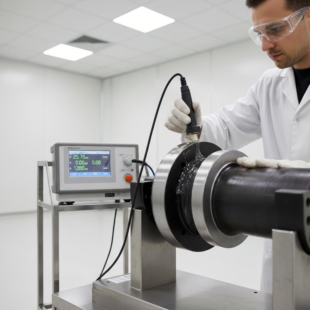
Detection methods for axle upset forging inspection include both non-destructive and destructive approaches:
- Ultrasonic testing: Sound waves penetrate the material to detect internal flaws. Research confirms this method detects cracks at axle locations in depths between 30 and 80 mm, making it essential for verifying internal integrity.
- Magnetic particle testing: Reveals surface and near-surface cracks by magnetizing the part and applying ferrous particles that gather at discontinuities
- Visual inspection: Fundamental first-line assessment using proper lighting and magnification to identify surface defects
- Hardness testing: Confirms heat treatment achieved required mechanical properties throughout the component
- Tensile testing: Destructive test on sample pieces verifying material strength meets specification
Dimensional Tolerances for Axle Applications
Beyond defect detection, dimensional verification confirms your upset forging operation produced the geometry your application requires. Axle components demand tight tolerances—particularly on bearing surfaces, mounting interfaces, and spline features where fit and function depend on precise dimensions.
Forging quality standards for axle applications typically specify tolerances based on feature type and function:
- Flange diameter: Typically ±1.0 mm for as-forged condition, tightened to ±0.1 mm after finish machining
- Flange thickness: ±0.5 mm as-forged, critical for mounting surface flatness
- Shaft diameter: ±0.5 mm as-forged in upset zone, finish machined to bearing fit requirements
- Concentricity: Shaft centerline to flange centerline within 0.5 mm TIR for as-forged parts
- Overall length: ±2.0 mm as-forged, accommodating downstream machining allowances
Measurement methods range from simple gauging for production floor verification to coordinate measuring machines (CMM) for detailed dimensional analysis. Statistical process control (SPC) helps identify trends before tolerances are exceeded, enabling proactive adjustments rather than reactive rejections.
The most effective axle quality control programs prevent defects through process control rather than simply detecting them through inspection. When you understand why forging defects occur, you can adjust parameters to eliminate root causes.
According to industry documentation, if the criteria of acceptability are not specified, relevant industry standards should be referenced to establish acceptance limits. For automotive axles, IATF 16949 quality management requirements establish systematic approaches to defect prevention and continuous improvement that extend far beyond simple inspection protocols.
With robust quality control verifying that your upset forged axles meet all specifications, one final consideration determines your long-term success—choosing the right manufacturing partner who can consistently deliver the quality, capability, and capacity your production demands.
Step 7 Partnering with a Qualified Axle Forging Supplier
You've mastered the technical fundamentals of upset forging for axles—from material selection through quality control. But here's the reality many manufacturers face: executing this process consistently at scale requires either significant capital investment or the right axle forging supplier partnership. Choosing the wrong automotive forging manufacturer leads to quality inconsistencies, missed deadlines, and components that fail when your customers need them most. So how do you evaluate potential partners effectively?
Certification Requirements for Automotive Axle Suppliers
When evaluating any forging company selection, certifications serve as your first filter. They verify that a supplier has implemented systematic quality management practices—not just claimed them. For automotive axle applications specifically, one certification stands above the rest.
According to IATF 16949 certification research, this globally recognized quality management standard is designed especially for the automotive industry, outlining requirements for a quality management system that helps organizations improve the overall efficiency of their manufacturing processes and enhance customer satisfaction.
Why does IATF 16949 forging certification matter so much? The standard builds on ISO 9001:2015 foundations but adds automotive-specific requirements that directly impact axle quality:
- Quality Management System (QMS): Suppliers must establish and maintain robust systems adhering to core principles including customer focus, continuous improvement, and evidence-based decision-making
- Planning and Risk Analysis: Organizations must identify and assess potential risks at different manufacturing stages and implement actions to mitigate them—critical for safety-critical axle components
- Process Management: A process-oriented approach with documented procedures, regular monitoring, and measured effectiveness ensures consistent forging results
- Product Design and Development: Robust development processes that account for customer requirements, safety regulations, and legal obligations
- Monitoring and Measurement: Continual operations monitoring including audits, inspections, and performance evaluations
Beyond IATF 16949, according to die forging supplier evaluation research, reputable suppliers should possess industry-specific accreditations relevant to their target markets. Environmental certifications like ISO 14001 and safety standards like ISO 45001 reflect responsible business practices that also mitigate potential compliance risks.
Evaluating Engineering and Prototyping Capabilities
Certifications confirm minimum standards—but what about actual capability? The best automotive forging manufacturers bring engineering expertise that adds value beyond simple production capacity. When you're developing new axle designs or optimizing existing ones, in-house engineering support accelerates your development cycle.
According to rapid prototyping research, traditional forging processes required lengthy tooling setups, repetitive testing cycles, and excessive material wastage. Tooling preparation for complex components could span 12-20 weeks, with validation cycles adding months.
Look for suppliers who have invested in capabilities that accelerate your timeline:
- Hybrid tooling approaches: Combining additive manufacturing for rapid die creation with CNC machining for precise finishing can reduce tooling lead times by up to 60%
- Digital simulation: Advanced finite element analysis (FEA) tools simulate material flow, predicting potential issues before physical trials—reducing iterations and costs
- Production-grade prototyping: Prototypes forged using the same alloys as final production ensure mechanical properties match, eliminating surprises during scale-up
The research indicates that modern rapid prototyping can accelerate development cycles from 4-6 months to just 6-8 weeks. For axle applications where time-to-market matters, this capability difference translates directly to competitive advantage.
Shaoyi (Ningbo) Metal Technology exemplifies these capabilities in practice—their in-house engineering team supports component development for drive shafts and similar automotive applications, with rapid prototyping timelines as short as 10 days for qualified projects. Their IATF 16949 certification confirms the systematic quality approach that automotive applications demand.
Production Flexibility from Prototype to Mass Volume
Your axle needs today might be 500 prototype units—but what about next year when production ramps to 50,000? Forging company selection must account for scalability. A supplier perfect for low-volume development work may lack capacity for production demands, while high-volume specialists might ignore small prototype orders entirely.
According to supplier evaluation research, evaluating production capabilities requires understanding forging press capacity, heat treatment facilities, and machining integration. The variety in equipment allows suppliers to cater to diverse customer needs and handle a wide spectrum of forging applications.
When assessing axle forging supplier flexibility, consider these evaluation criteria:
- Press range and capacity: Does the supplier have equipment appropriate for your axle dimensions? Tonnage requirements vary significantly from small steering components to heavy-duty drive axles
- Heat treatment integration: In-house capabilities for normalizing, quenching, and tempering reduce lead times and improve quality control versus outsourced treatment
- Machining capabilities: CNC turning, grinding, and finishing operations under one roof streamline the complete workflow from forged blank to finished component
- Volume scalability: Can the supplier ramp from prototype quantities to full production without quality degradation or delivery delays?
- Logistics positioning: Geographic location affects shipping costs and lead times—suppliers near major ports offer advantages for global supply chains
Shaoyi's location near Ningbo Port provides exactly this logistics advantage for customers requiring global delivery. Their production flexibility spans from rapid prototyping through high-volume mass production, with integrated capabilities including hot forging and precision machining for automotive components like suspension arms and drive shafts.
The research emphasizes that high-quality suppliers maintain comprehensive documentation and traceability systems—detailed records of material certifications, process parameters, and inspection results that prove essential when quality questions arise or regulatory compliance requires demonstration.
The right manufacturing partner doesn't just execute your specifications—they bring engineering expertise, quality systems, and production flexibility that make your axle development faster, more reliable, and more cost-effective.
With a qualified supplier partnership in place, you've completed the essential framework for producing upset forged axles that deliver the performance and longevity your applications demand. The final section consolidates key takeaways and positions you for successful implementation.
Mastering Upset Forging for High-Performance Axle Production
You've now walked through every phase of the axle manufacturing process—from selecting the right steel grade to partnering with a qualified supplier. But mastering upset forging isn't about memorizing steps. It's about understanding how each phase connects to create axles that outlast the competition. Whether you're producing drive axles for heavy-duty trucks, steering components for agricultural equipment, or trailer axles for commercial transport, the fundamentals remain consistent: precise material selection, controlled heating, proper die setup, executed upset operations, optimized heat treatment, rigorous quality control, and reliable manufacturing partnerships.
Key Takeaways for Successful Axle Upset Forging
What separates consistently excellent axle production from hit-or-miss results? The forging best practices that matter most come down to process control at every stage:
- Material integrity starts everything: Verify steel grade certifications, inspect stock surfaces, and confirm dimensional specifications before any heating begins
- Temperature uniformity drives quality: Whether using induction or furnace heating, ensure the entire deformation zone reaches target temperature within ±20°C
- Respect the upset ratio limits: Keep unsupported length below 2.5 times bar diameter to prevent buckling—exceed this, and you're asking for defects
- Heat treatment transforms properties: Properly executed quenching and tempering cycles deliver the strength-toughness balance axle applications demand
- Inspection prevents failures: Implement checkpoints throughout production rather than relying solely on final inspection
The single most critical success factor in automotive axle production is maintaining consistent process parameters across every forging cycle—temperature, pressure, timing, and material handling must remain controlled and documented.
Industry Applications Across Automotive and Heavy Equipment
The upset forging techniques you've learned apply across remarkably diverse sectors. In the automotive industry, according to forging industry research, upset forging creates parts such as axles, bolts, and large screws that require high strength and precision. Heavy equipment axle forging follows the same principles but often at larger scales—mining trucks, construction equipment, and agricultural machinery all depend on upset-forged components to handle extreme loads in harsh conditions.
Agricultural applications present unique demands: axles must resist corrosive environments while handling variable loads from field operations. The grain flow alignment achieved through proper upsetting delivers exactly the fatigue resistance these conditions require. Similarly, heavy equipment axle forging for construction and mining equipment prioritizes impact resistance and durability under punishing operational cycles.
Moving Forward with Your Axle Production Project
Ready to implement what you've learned? Start by evaluating your current process against these fundamentals. Are you maintaining proper temperature control throughout heating? Does your die maintenance program prevent wear-related quality drift? Have you established inspection checkpoints that catch defects before they become expensive problems?
For organizations without in-house forging capabilities, supplier selection becomes your most important decision. Look for IATF 16949 certification, demonstrated engineering expertise, and production flexibility that can grow with your requirements. The right partner brings more than manufacturing capacity—they contribute process knowledge that continuously improves your axle performance.
The axle manufacturing process you've mastered here represents decades of metallurgical understanding and manufacturing refinement. Apply these principles consistently, and you'll produce axles that don't just meet specifications—they exceed expectations in the demanding real-world conditions where performance truly matters.
Frequently Asked Questions About Upset Forging for Axles
1. What is the upsetting forging process?
Upset forging involves locally heating a metal bar, gripping it firmly with specialized tooling, and applying compressive pressure along its axis to increase the diameter while reducing length. For axles, this process creates robust flanges, mounting surfaces, and connection points by forcing heated metal to flow into precisely shaped die cavities. The technique aligns grain structure parallel to part contours, dramatically improving fatigue resistance and mechanical properties in high-stress areas.
2. What is the process of forging axle shafts?
Axle shaft forging follows seven key steps: selecting appropriate steel grades like AISI 4340 or 4140, heating blanks to 1,100-1,200°C using induction or gas furnaces, setting up dies and positioning workpieces with precise alignment, executing the upset stroke to form flange geometry, applying heat treatment sequences including quenching and tempering, performing finish machining operations, and conducting quality inspections throughout production. This systematic approach ensures axles meet demanding load-bearing requirements.
3. What are the rules for upset forging?
Three fundamental rules govern defect-free upset forging: the maximum unsupported stock length in a single pass cannot exceed three times the stock diameter (practically kept below 2.5d), if longer stock is used the die cavity width must not exceed 1.5 times stock diameter, and for even longer stock, the punch must feature a conical recess. Following these guidelines prevents buckling during compression and ensures proper material flow into die cavities.
4. Why is upset forging preferred for axle manufacturing?
Upset forging delivers superior axle performance through enhanced grain flow alignment that follows part contours, providing natural reinforcement in high-stress zones. The process offers up to 15% material savings compared to alternatives, achieves tight tolerances reducing secondary machining, and increases component lifespan by up to 30%. Unlike open-die or roll forging, upset forging specifically increases diameter at targeted locations—exactly what axle flanges and mounting surfaces require.
5. What certifications should an axle forging supplier have?
IATF 16949 certification is essential for automotive axle suppliers, as it establishes systematic quality management specifically designed for automotive manufacturing. This certification ensures suppliers maintain robust quality systems, implement risk analysis at each production stage, and follow documented procedures with regular monitoring. Additional certifications like ISO 14001 for environmental management and ISO 45001 for safety standards indicate responsible business practices. Suppliers like Shaoyi (Ningbo) Metal Technology combine IATF 16949 certification with rapid prototyping capabilities and integrated CNC machining for complete axle production solutions.