 Small batches, high standards. Our rapid prototyping service makes validation faster and easier —

CNC Sheet Metal Fabrication: Key Decisions That Make Or Break Your Project
What CNC Sheet Metal Fabrication Actually Means
Ever wondered how manufacturers transform flat metal sheets into the precisely shaped components inside your car, smartphone, or kitchen appliances? The answer lies in a process that combines digital precision with versatile metal forming techniques. Understanding this distinction is crucial before you commit to any manufacturing project.
CNC sheet metal fabrication is a sophisticated manufacturing technique that uses computer-controlled machines to cut, bend, and shape thin metal sheets into precision components. Unlike CNC machining that removes material from solid blocks, this process works with flat sheets—typically ranging from 0.5mm to 6mm thick—transforming them through cutting, bending, and forming operations.
From Flat Sheet to Finished Part
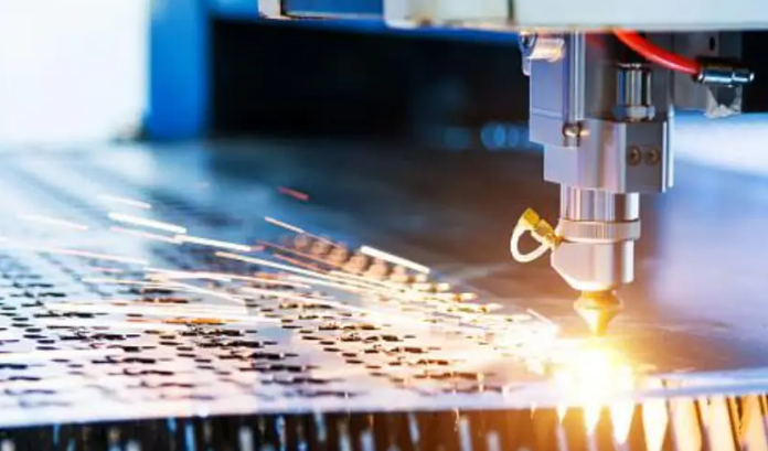
Think of cnc sheet metal as a digital sculptor working with flexible canvases instead of solid blocks. The process begins with a flat metal sheet and uses software-driven tools to execute precise cuts and bends. Laser cutters trace intricate patterns, bending machines fold precise angles, and punching equipment creates holes and features—all guided by computer programs that ensure consistency across hundreds or thousands of parts.
This differs significantly from traditional manual methods where skilled workers relied on hand tools and experience. While craftsmanship still matters, the CNC meaning in this context refers to the computer numerical control that eliminates human error and enables repeatability. Your first part looks identical to your thousandth part.
The Digital Revolution in Metal Forming
Here's where many people get confused. Pure CNC machining starts with solid material blocks and carves away everything that isn't the final part. Sheet metal fabrication takes a fundamentally different approach—it shapes thin sheets through cutting, bending, and forming rather than subtractive removal.
Why does this matter for your project? The distinction affects everything from cost to lead time to design possibilities. Metal fabrication using sheet materials typically proves more economical for enclosures, brackets, chassis, and structural components. You're not paying to machine away 80% of your raw material.
The machining metalworking landscape has evolved dramatically as these technologies merged. Modern facilities combine multiple CNC processes—laser cutting for precision profiles, CNC bending for accurate angles, and punching for repetitive features—into streamlined production workflows. This integration is precisely why industries from aerospace to electronics now depend on this manufacturing method for components requiring both precision and production efficiency.
Throughout this guide, you'll discover the eight critical decisions that determine whether your project succeeds or struggles. Each choice—from process selection to material matching to partner evaluation—builds on this foundational understanding of what CNC sheet metal fabrication actually delivers.
Core Processes in CNC Sheet Metal Manufacturing
Now that you understand what distinguishes sheet metal fabrication from traditional machining, the next critical decision involves selecting the right processes for your specific project. Here's the challenge: most manufacturers specialize in just two or three techniques, which limits your options. Understanding the full spectrum of available methods puts you in control of the conversation and helps you match your requirements to the optimal production approach.
Cutting Technologies Compared
Your cutting method choice affects everything—from achievable tolerances to edge quality to per-part costs. Each technology excels in specific scenarios, and selecting the wrong one can derail your project before forming even begins.
Laser cutting has become the workhorse of modern cnc sheet metal fabrication. A focused laser beam melts through material with surgical precision, delivering excellent edge quality on thin to medium-thickness materials. According to IWM Waterjet's comparative analysis, a 6kW laser cutter can slice through steel up to 25mm (1 inch) thick, though optimal performance occurs with non-reflective mild steel under 6.35mm (0.25 inch). The speed advantage makes laser cutting steel particularly attractive for high-volume production runs where cycle time directly impacts your bottom line.
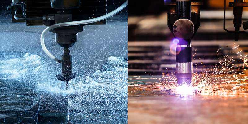
Plasma cutting offers a cost-effective alternative for thicker conductive metals. The process generates temperatures between 20,000 and 50,000 degrees Fahrenheit, essentially melting through material at impressive speeds. However, this thermal intensity creates a wider kerf—the material removed during cutting—and produces rougher edges that may require secondary finishing. Plasma systems typically handle aluminum up to 6 inches thick, making them ideal for structural components where precision takes a back seat to material capacity.
Waterjet cutting solves problems that thermal methods simply cannot address. By propelling abrasive garnet particles through a supersonic water stream, this cold-cutting process eliminates heat-affected zones entirely. Waterjet excels at cutting thick materials—steel up to 100mm (4 inches)—and handles virtually any material, including glass, ceramic, and composites. When you're working with heat-sensitive alloys or materials that would distort under thermal stress, waterjet becomes your only viable option.
CNC punching takes a fundamentally different approach. Rather than cutting continuous profiles, a metal cutter using punch tooling creates holes, slots, and features through high-speed die impacts. This method proves exceptionally efficient for parts requiring numerous repetitive features—think ventilation panels or electrical enclosures with dozens of mounting holes. While a die cut machine limits you to available tooling shapes, the speed advantage for batch production often outweighs the flexibility of profile cutting.
| Cutting Method | Material Thickness Range | Tolerance Capability | Edge Quality | Speed | Ideal Applications |
|---|---|---|---|---|---|
| Laser Cutting | 0.5mm - 25mm steel | ±0.001" (±0.025mm) | Excellent | Very fast (thin materials) | Precision parts, intricate profiles, non-reflective metals |
| Plasma Cutting | Up to 6" aluminum | ±0.030" to ±0.060" | Fair | Fast | Thick conductive metals, structural components |
| Waterjet | Up to 4" steel (100mm) | ±0.003" (±0.1mm) | Good | 5-10x slower than EDM | Heat-sensitive materials, thick sections, non-metals |
| CNC Punching | Thin sheets (typically under 6mm) | Fair | Fair | Fast batch production | Repetitive features, holes, short-run prototypes |
Forming and Bending Operations
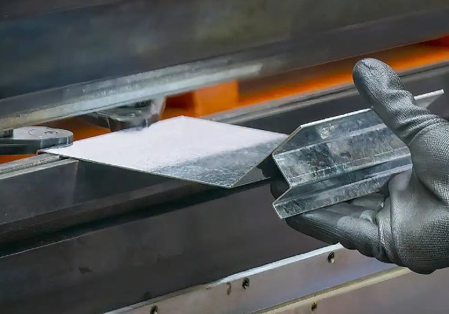
Cutting produces flat profiles—bending transforms them into three-dimensional components. CNC press brakes use precision-controlled tooling to fold sheet metal along programmed bend lines, achieving consistent angles across entire production runs.
Modern bending equipment calculates springback compensation automatically. Different materials and thicknesses behave differently when force is released, and advanced controllers adjust bend angles to compensate. This means your 90-degree corner actually ends up at 90 degrees, not 87 or 93.
Beyond simple bends, forming operations create complex geometries through techniques like hemming, seaming, and deep drawing. These secondary processes expand what's achievable from flat sheet stock, enabling features like rolled edges, stiffening ribs, and curved surfaces. When combined with cnc steel cutting for initial blank creation, these forming operations deliver components that would otherwise require expensive casting or machining operations.
Finishing Processes That Complete the Part
Raw fabricated parts rarely ship directly to customers. Finishing operations address edge quality, surface appearance, and functional requirements that cutting and forming alone cannot achieve.
Deburring removes sharp edges and micro-burrs left by cutting operations. While waterjet produces minimal burr and laser cutting generates little to none on thin materials, most parts benefit from some edge treatment before assembly or handling.
Welding integration joins multiple fabricated components into larger assemblies. CNC-fabricated parts offer consistent fit-up dimensions that simplify welding operations and improve joint quality. Whether you're using MIG, TIG, or spot welding, parts that arrive with precise dimensions reduce rework and assembly time.
Surface treatments like powder coating, plating, or anodizing often follow fabrication. The edge quality from your cutting process directly affects how well these coatings adhere and appear. Laser-cut edges typically accept finishes without additional preparation, while plasma-cut parts may require grinding or sanding before coating.
Understanding how these processes interconnect helps you specify requirements that optimize the entire production chain—not just individual operations. Your next critical decision involves matching these capabilities to specific tolerance requirements.
Precision and Tolerance Capabilities Explained
You've selected your cutting method and understand the forming operations available. Now comes a decision that separates successful projects from costly failures: defining your tolerance requirements. Here's the reality—most manufacturers never discuss specific tolerance capabilities, leaving you guessing whether your precision needs are even achievable. Let's change that.
Tolerance in sheet metal cnc operations refers to the acceptable deviation from your specified dimensions. According to Yijin Hardware's tolerance guide, typical sheet metal manufacturing tolerances range from ±0.005" to ±0.060"—a twelve-fold difference that dramatically affects both part functionality and production costs.
Tolerance Ranges by Process Type
Each cnc machine sheet metal process delivers different precision capabilities. Understanding these ranges before you finalize designs prevents expensive surprises during production.
Laser cutting achieves the tightest tolerances among thermal cutting methods. For standard production, expect linear tolerances of ±0.45mm, with high-precision operations reaching ±0.20mm. Hole diameter tolerances prove even tighter—±0.12mm for standard work and ±0.08mm for precision applications, according to Komacut's process tolerance specifications. Material thickness directly affects these numbers: thinner sheets (0.5mm to 2.0mm) hold tolerances of ±0.05mm, while thicker materials (10mm to 20mm) expand to ±0.50mm.
CNC bending introduces additional variables. Standard angular tolerances run ±1.0 degree, tightening to ±0.5 degree for high-precision work. Linear XYZ tolerances after bending typically match laser cutting at ±0.45mm standard or ±0.20mm for precision applications. The challenge? Each bend compounds potential deviation, making multi-bend parts inherently less precise than single-bend components.
Welding operations allow the widest tolerance bands—typically ±0.5mm to ±2mm for linear dimensions and ±2 degrees for angular measurements. When your assembly requires welded joints, design your tolerance stack-up accordingly.
Stamping delivers exceptional repeatability once tooling is set. Expect tolerances from ±0.1mm to ±0.5mm for most dimensions, with critical features achieving ±0.05mm. High-volume production justifies the tooling investment for parts requiring consistent precision.
When Precision Matters Most
Not every dimension on your part requires tight tolerance control. Identifying critical features versus general dimensions directly impacts both manufacturability and cost. Just as you might reference a drill bit size chart or drill size chart to select the right tool for specific hole requirements, understanding which dimensions demand precision helps you communicate effectively with fabricators.
Several factors influence the dimensional accuracy your fabricator can actually achieve:
- Material type and properties: Stainless steel permits tighter tolerances (±0.005") than aluminum (±0.010") due to lower malleability and higher strength. A sheet metal gauge chart helps you understand how material thickness affects achievable precision across different alloys.
- Thickness consistency: Raw material varies between sheets and even within the same sheet. Cold-rolled steel offers tighter thickness tolerances than hot-rolled, making it preferable for precision applications.
- Machine calibration: Even a 0.1-degree press brake misalignment causes measurable deviation in bent parts. Advanced CNC machines achieve tolerances up to ±0.001" when properly maintained.
- Tooling condition: Precision-ground dies maintain tolerances up to five times longer than standard steel tooling. Worn tools produce inconsistent results regardless of machine capability.
- Part complexity: Simple, symmetrical parts typically hold ±0.010" tolerances, while complex geometries with multiple features may require ±0.030" or looser.
- Thermal effects: Cutting methods like laser and plasma generate heat that causes expansion and contraction, impacting final dimensions on heat-sensitive materials.
Industries where tight tolerances prove non-negotiable include aerospace components requiring weight optimization through minimal material variance, medical devices demanding exact fit for patient safety, and electronics enclosures where thermal management depends on precise contact surfaces. Automotive applications often specify gauge sizes precisely because chassis and structural components must align consistently across thousands of assemblies.
Understanding your tolerance requirements connects directly to material selection—the next decision that shapes your project's success. Different metals respond to fabrication processes differently, and matching materials to methods determines whether your precision targets remain achievable.
Material Selection for CNC Sheet Metal Projects
You've defined your tolerance requirements and understand the processes available. Now comes a decision that influences every subsequent step: choosing the right material. Here's the problem—most fabricators assume you already know which metal sheet works best for your application. That assumption leads to mismatched materials, production headaches, and parts that underperform in the field.
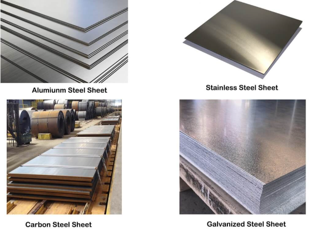
Each material behaves differently under CNC processes. Aluminum sheet metal cuts faster but scratches easily during handling. Stainless steel sheet delivers exceptional durability but demands more powerful equipment. Galvanized sheet metal resists corrosion but releases harmful fumes during thermal cutting. Understanding these trade-offs before you specify materials prevents costly mid-project changes.
Matching Materials to Methods
The relationship between material properties and process selection determines both quality and cost. According to Zintilon's sheet metal materials guide, factors like hardness, thermal conductivity, and formability directly influence which CNC method delivers optimal results.
Aluminum sheet offers the lightest weight among common fabrication materials while providing excellent corrosion resistance even without additional coatings. Its high thermal conductivity makes laser cutting highly effective—heat dissipates quickly, producing clean edges with minimal distortion. However, aluminum's reflective surface can challenge lower-power laser systems. For cutting operations, expect maximum thicknesses around 40mm with 10,000-watt fiber lasers, though quality cutting typically stays under 8mm for most equipment.
Stainless steel sheet metal combines strength with corrosion resistance, making it the preferred choice for food processing, medical equipment, and architectural applications. The material contains at least 13% chromium plus nickel and molybdenum, creating a self-healing oxide layer that resists rust. Stainless steel requires more laser power than carbon steel—a 3000W laser cuts stainless up to 10mm, while carbon steel of the same thickness requires only 2000W according to HGTECH's cutting thickness guide.
Galvanized sheet metal provides cost-effective corrosion protection through its zinc coating. Two main types exist: electro-galvanized sheets (zinc coating without spangle) and hot-dipped sheets (iron-zinc alloy with pure zinc coating). The hot-dipped variety offers superior corrosion resistance at lower cost. However, cutting galvanized material requires proper ventilation—the zinc coating vaporizes during laser and plasma cutting, creating potentially hazardous fumes.
Carbon steel remains the workhorse material for structural applications. Available in low, medium, and high carbon content levels, each variant serves different purposes. Low carbon steel offers excellent formability for everyday items like enclosures and brackets. Medium carbon steel provides the strength needed for automotive and appliance components. High carbon steel, while more brittle, delivers the hardness required for cutting tools and precision components.
| Material Type | Recommended CNC Processes | Optimal Thickness Range | Key Properties | Application Notes |
|---|---|---|---|---|
| Aluminum Sheet | Laser cutting, CNC punching, waterjet | 0.5mm - 8mm (quality cut) | Lightweight, high thermal conductivity, corrosion resistant | Aerospace, electronics, heat sinks; avoid low-power lasers on reflective alloys |
| Stainless Steel Sheet | Laser cutting, waterjet, plasma (thick sections) | 0.5mm - 12mm (laser); up to 50mm (10kW+) | Excellent corrosion resistance, high strength, hygienic | Food processing, medical devices, architectural; requires higher laser power |
| Galvanized Steel | Laser cutting, CNC punching, plasma | 0.5mm - 6mm typical | Corrosion resistant coating, cost-effective | HVAC, construction, outdoor enclosures; ensure proper ventilation during cutting |
| Carbon Steel | Laser cutting, plasma, waterjet, punching | 0.5mm - 20mm (laser); up to 100mm (waterjet) | High strength, excellent formability, weldable | Structural components, automotive chassis, general fabrication |
| Copper | Waterjet, specialized laser | 0.5mm - 5mm | Excellent conductivity, antimicrobial, highly reflective | Electrical components, heat exchangers; challenging for standard lasers |
| Tool Steel | Waterjet, EDM, specialized laser | 1mm - 25mm | Extreme hardness, abrasion resistant, heat tolerant | Dies, punches, cutting tools; requires post-processing for hardness |
Thickness Guidelines for Optimal Results
Selecting the right gauge goes beyond simply choosing a number from a sheet metal gauge chart. According to Sinoway Industry's thickness selection guide, the gauge number inversely relates to thickness—a 14 gauge steel thickness measures approximately 1.9mm (0.0747 inches), while 11 gauge steel thickness reaches about 3.0mm (0.1196 inches).
Different CNC methods perform optimally within specific thickness ranges:
- Thin gauge materials (under 3mm): Laser cutting excels here, delivering fast speeds and excellent edge quality. CNC punching also performs well for parts with repetitive features. Avoid plasma cutting—the heat input overwhelms thin materials, causing warping and poor edge definition.
- Medium gauge (3mm - 10mm): Laser cutting remains effective, though speeds decrease as thickness increases. A 6000W laser cuts 8mm stainless steel at speeds 400% faster than a 3kW system. Plasma becomes viable for less critical tolerance requirements.
- Thick plate materials (over 10mm): Waterjet cutting handles thick sections without heat distortion—up to 100mm steel. High-power lasers (10kW+) cut carbon steel up to 20mm with bright surface finish, while plasma offers speed advantages for structural applications where edge quality matters less.
Consider these material properties when matching thickness to process:
- Hardness: Harder materials like tool steel require more powerful equipment and slower cutting speeds. Softer materials like aluminum cut faster but may produce more burr.
- Thermal conductivity: Aluminum's high thermal conductivity actually helps laser cutting by quickly dissipating heat. Stainless steel's lower conductivity concentrates heat, requiring adjusted parameters.
- Formability: If your part requires bending after cutting, material ductility matters. Aluminum and low-carbon steel bend easily, while high-carbon steel and hardened alloys may crack during forming operations.
- Weldability: Some materials weld easily while others demand specialized techniques. Carbon steel welds readily; stainless steel requires specific filler materials; aluminum demands specialized equipment and expertise.
The interplay between material selection and achievable results extends beyond the fabrication floor. Your design file preparation and DFM considerations—covered in the next section—must account for how your chosen material behaves during each production step.
Design Preparation and DFM Essentials
You've selected your material and understand tolerance capabilities. Now comes a decision that many engineers overlook until problems emerge on the production floor: preparing design files that actually manufacture cleanly. Here's the reality—most fabrication delays trace back to design issues, not equipment failures or material problems. Understanding sheet metal fabrication techniques from a design perspective saves weeks of revision cycles and thousands in rework costs.
Design File Requirements for Production
Your CAD software creates beautiful 3D models, but CNC equipment reads specific file formats. This translation step causes more production headaches than most engineers realize.
For cnc sheet metal cutting operations, most fabricators accept DXF or DWG files representing the flat pattern. These 2D formats communicate cutting paths directly to laser, waterjet, or plasma equipment. However, file preparation matters—nested geometry, overlapping lines, or open contours cause machine errors that halt production.
Bent parts require additional consideration. STEP files preserve 3D geometry that allows fabricators to verify bend sequences and check for tooling interference. According to SendCutSend's CAD to Cut guide, proper sheet metal modeling in software like Fusion 360 or SolidWorks includes K-factor settings and bend allowance calculations that match your fabricator's equipment. When these parameters align, flat patterns export correctly the first time.
Software compatibility considerations extend beyond file formats:
- Gauge tables: Your CAD software needs accurate material thickness and bend parameters. Many fabricators provide downloadable gauge tables that configure your modeling environment to match their press brake settings.
- K-factor values: This ratio describes how material stretches during bending. According to The Fabricator's bend radius guide, using the fab shop's calculation values ensures flat layouts are ready for manufacturing without revision.
- Units and scale: Metric versus imperial mismatches create parts that arrive at wrong dimensions. Always verify units before exporting production files.
DFM Principles That Save Time and Money
Design for Manufacturability transforms good designs into great parts. When you're machining sheet metal or planning cnc sheet metal forming operations, certain principles prevent common failure modes before they occur.
According to Incodema's sheet metal design guide, the following DFM considerations directly impact production success:
- Minimum bend radii: The 1x thickness rule works for steel and stainless steel—specify an inside bend radius at least equal to material thickness. Aluminum alloys like 6061-T6 require larger radii (minimum 3x to 6x thickness) to prevent cracking. Setting radii close to thickness gives fabricators flexibility in tooling selection, potentially reducing scrap and production time.
- Hole-to-edge distances: Features placed too close to bend lines distort during forming. Maintain minimum spacing of 2 to 2.5 times material thickness from hole edges to bend radius tangency. Lesser spacing requires secondary operations after bending, adding manufacturing costs.
- Relief cuts: Where edge flanges intersect or features approach bend lines, relief cuts prevent tearing and cracking. Design cut and bend reliefs with minimum width of 2.5 times material thickness. Relief depth should equal bend radius plus material thickness plus 0.020 inches according to SendCutSend's guidelines.
- Grain direction: Raw material grain impacts forming characteristics in all materials, particularly mill-hardened alloys. Bends perpendicular to grain direction reduce cracking risk. Small-radius bends parallel to grain may fracture in harder tempers.
- Minimum flange length: During bending, material must bridge fully across the V-die. For air bending on press brakes, 3x material thickness represents the minimum safe flange size. Folding machines accommodate shorter flanges since they lack V-die tooling constraints.
- U-channel access: Closely spaced bends require tooling clearance for the second bend operation. When the first flange swings into position during forming, it may interfere with the brake frame or tooling. Complex U-channels may require welded assembly from separate L and I sections.
Flat parts from lasers or CNC punching equipment typically achieve consistency within ±0.004 inches. Precision brakes repeat within ±0.004 inches as well. However, variation in raw material thickness increases recommended precision to ±0.010 inches per bend. Setting tolerances with these manufacturing realities in mind prevents rejected parts and costly disputes.
Proper fabrication and machining preparation extends beyond individual features. Consider how tolerance stacking affects assemblies—small variations in multiple features compound, potentially causing alignment issues when parts come together. Dimensioning from common origins rather than daisy-chaining measurements helps avoid compounding errors.
Understanding these design principles connects directly to your next critical decision: selecting the right CNC process for your specific project characteristics, volume requirements, and timeline constraints.
Choosing the Right CNC Sheet Metal Process
You've prepared your design files and understand DFM principles. Now comes the decision that directly impacts your project budget and timeline: matching your specific requirements to the optimal manufacturing process. Here's what most guides miss—the best cnc machine for metal work isn't universally "best." It's the one that aligns with your volume, complexity, material, and deadline requirements.
This decision separates projects that run smoothly from those plagued by delays and budget overruns. Let's build a framework that guides you toward the right choice every time.
Project Characteristics That Drive Method Selection
Think of process selection as solving a puzzle where four pieces must fit together: part complexity, material requirements, tolerance demands, and production quantity. When these factors align with process capabilities, you've found your answer.
Part geometry complexity immediately narrows your options. Simple brackets with straight cuts and basic bends? Laser cutting combined with CNC bending handles these efficiently. Intricate profiles with tight interior features? Laser cutting excels here too. Parts requiring dozens of identical holes? CNC punching delivers faster cycle times. Complex contours in thick, heat-sensitive materials? Waterjet becomes your only practical choice.
Material selection further constrains the decision. According to Komaspec's fabrication process guide, plasma cutting only works with electrically conductive materials, eliminating plastics and composites from consideration. Reflective materials like copper challenge standard laser systems. Meanwhile, cnc machine metal operations using waterjet handle virtually any material—but at slower speeds and higher costs.
Tolerance requirements establish capability thresholds. When your design demands ±0.05mm precision, stamping or precision laser cutting become mandatory. For structural components with ±0.5mm tolerances, faster and cheaper options like shearing or plasma cutting may suffice. Understanding fabrication vs machining distinctions helps here—sheet metal fabrication typically achieves looser tolerances than CNC machining from solid blocks, but at significantly lower cost for appropriate geometries.
The decision matrix below maps these characteristics to recommended processes:
| Project Characteristic | Laser Cutting + Bending | CNC Punching | Manual Stamping | Progressive Stamping | Waterjet |
|---|---|---|---|---|---|
| Part Complexity | High (intricate profiles) | Medium (repetitive features) | Medium (restricted geometry) | Medium-High (complex forms) | Very High (any contour) |
| Tolerance Capability | ±0.10mm linear | ±0.10mm | ±0.05mm to 0.10mm | ±0.05mm to 0.10mm | ±0.1mm (0.003") |
| Material Thickness | 0.5mm - 20mm | 0.5mm - 4mm | 0.5mm - 4mm | 0.5mm - 4mm | Up to 100mm |
| Ideal Volume | 1 - 1,000s | 100s - 1,000s | 3,000 - 10,000+ | 10,000 - 100,000+ | 1 - 100s |
| Heat-Sensitive Materials | Limited | Yes (no heat) | Yes (no heat) | Yes (no heat) | Excellent (cold cutting) |
| Tooling Required | None | Standard available | Custom ($250 - $50k+) | Custom ($10k - $100k+) | None |
Volume and Lead Time Considerations
Production quantity fundamentally reshapes the economics of metal machining and metal fabrication and machining decisions. What works brilliantly for ten prototypes becomes financially disastrous at ten thousand units—and vice versa.
According to Sigma Design's production volume analysis, the transition between manufacturing methods follows predictable cost curves. Their model demonstrates that a sheet metal part with $200 laser and press brake setup costs $3.73 per unit at the cost floor. The same part using progressive die tooling costs $35,000 upfront but drops to just $0.50 per unit at scale. The crossover point determines which approach saves money.
Low volume (1 - 1,000 units): Laser cutting and CNC bending dominate this range. No custom tooling means production starts within days. According to Komaspec's data, sampling takes 5 days or less, with mass production runs completing in approximately 10 days. These methods suit prototyping, design validation, and small-batch production where speed trumps per-unit cost.
Mid volume (1,000 - 10,000 units): This transitional range requires careful analysis. Manual stamping becomes viable for parts requiring tight tolerances—tooling costs from $250 to $50,000 amortize across larger runs. However, EABEL's analysis notes the crossover typically occurs between a few dozen to a few hundred parts depending on complexity. Bridge tooling or soft tooling can test designs before committing to hardened production dies.
High volume (10,000+ units): Progressive stamping delivers the lowest per-unit costs, but demands commitment. Tooling requires 45-55 days before production starts, with costs ranging from $10,000 to over $100,000. Once running, however, production speeds and consistency make other methods uncompetitive. This explains why automotive and consumer electronics industries rely almost exclusively on progressive stamping for cnc metal components.
Lead time considerations extend beyond tooling creation:
- Design iteration needs: If your design hasn't completed prototyping and field testing, avoid long lead time processes. Laser cutting allows design changes as simple as updating the drawing and recutting. Stamping die modifications cost thousands and delay production weeks.
- Production scheduling: Large orders require manufacturers to allocate equipment and labor. Expect longer lead times for substantial runs—your fabricator needs to plan capacity.
- Secondary operations: Welding, finishing, and assembly add time. Complex assemblies with extensive welding can extend takt times to 30 minutes per part or more, according to Komaspec's process analysis.
The table below summarizes cost and timing relationships:
| Process | Tooling Cost | Part Cost | Sampling Lead Time | Production Lead Time | Best Volume Range |
|---|---|---|---|---|---|
| Laser Cutting + Bending | None | Medium | ≤5 days | 10 days | 1 - 1,000s |
| CNC Punching | Low | Low-Medium | 5 days | 10 days | 100s - 1,000s |
| Manual Stamping | Medium ($250 - $50k+) | Low | 30-40 days (tooling) | 15 days | 3,000 - 10,000+ |
| Progressive Stamping | High ($10k - $100k+) | Very Low | 45-55 days (tooling) | 15 days | 10,000 - 100,000+ |
| Waterjet | None | Medium-High | ≤5 days | Variable | 1 - 100s |
Making the right process decision requires honest assessment of where your project falls on these spectrums. A prototype run of 50 brackets using progressive stamping wastes tens of thousands on tooling that won't amortize. Conversely, producing 100,000 units via laser cutting sacrifices the cost advantages that make your product competitive.
Understanding these trade-offs prepares you for the next critical consideration: how different industries apply these processes to solve specific manufacturing challenges.
Industry Applications and Real-World Uses
You've learned how to select processes, materials, and tolerance specifications. Now comes the perspective shift that transforms theoretical knowledge into practical decision-making: understanding how different industries actually apply CNC sheet metal fabrication to solve their unique manufacturing challenges. Here's what separates successful projects—industry context shapes every decision you've made so far.
According to FACTUREE's industry analysis, professional sheet metal work forms the structural foundation of thousands of applications across key sectors. What do a state-of-the-art control cabinet in mechanical engineering, a precision-manufactured front panel in medical technology, and the robust housing of an electric car charging station have in common? They would all be unthinkable without professional steel fabrication processes. Let's examine how each industry prioritizes different factors—and what that means for your project decisions.
Automotive Chassis and Structural Components
In the automotive industry, especially in e-mobility applications, every gram matters. CNC sheet metal fabrication enables the production of lightweight yet highly stable components that balance strength with weight reduction.
Typical automotive applications include:
- Battery housings and protective enclosures for electric vehicles
- Chassis components and structural reinforcements
- Body panels and exterior trim pieces
- Bracket assemblies and mounting hardware
- Heat shields and thermal management components
Automotive metal fab prioritizes volume production and consistency above all else. When you're manufacturing thousands of identical brackets or enclosures, process repeatability determines success. This explains why progressive stamping dominates high-volume automotive production—once tooling is validated, each part matches the last within tight specifications.
Material selection in automotive applications typically centers on high-strength steels and aluminum alloys. Production is often characterized by complex bend sequences and the creation of complete welded assemblies. Aluminum welding expertise becomes critical when joining lightweight structural components that must withstand crash loads while minimizing vehicle weight.
Precision Requirements Across Industries
Beyond automotive, each sector brings distinct priorities that reshape how steel fabricators approach projects. Understanding these differences helps you communicate requirements effectively and select partners with relevant experience.
Aerospace Applications
In aerospace, compromises on safety are simply not an option. Sheet metal processing supplies essential components that must withstand extreme loads while maintaining minimal weight. Typical applications include:
- Skin panels for aircraft fuselages and control surfaces
- Internal brackets and support structures
- Engine component housings and heat shields
- Interior panels and storage systems
Aerospace emphasizes weight reduction and tight tolerances simultaneously—a challenging combination. High-performance materials like titanium and special aluminum alloys require maximum precision through processes such as 5-axis laser cutting or waterjet cutting to minimize thermal influences. Complex forming processes and certified welding procedures are standard requirements. When you're searching for metal fabricators near me with aerospace capabilities, certification and traceability documentation become non-negotiable evaluation criteria.
Electronics and IT Applications
Where electrical components need protection, organization, and cooling, sheet metal parts prove indispensable. Functionality and exact dimensions drive every decision. Typical electronics applications include:
- Control cabinet housings and enclosures
- Server rack components and chassis
- EMI shielding enclosures
- Heat sink assemblies and thermal management brackets
- Front panels with precisely cut display apertures
Electronics requires intricate features and clean edges that won't damage sensitive components during assembly. The material of choice is often lightweight aluminum alloys—raw or with anodized aluminum finishes for corrosion resistance and aesthetic appeal. Precise laser cutting produces burr-free edges, while pressing in fastening elements simplifies subsequent assembly operations.
Architecture and Construction
In modern construction, sheet metal parts combine function with design. They characterize the appearance of buildings while providing extreme durability. Typical architectural applications include:
- Facade cladding panels and decorative elements
- Roofing components and drainage systems
- Interior wall systems and ceiling panels
- Structural brackets and connection hardware
- Custom signage and wayfinding elements
Architectural projects prioritize weather resistance and visual consistency. The range of materials extends from brushed stainless steel and Corten steel to powder-coated or painted aluminum. Powder coating services deliver the wide variety of colors and textures that architects specify, while providing maximum protection against environmental influences.
Medical Technology
In medical technology, the focus is on human health and the reliability of diagnostic devices. Sheet metal parts must meet the highest standards of hygiene, cleanability, and biocompatibility. Typical applications include:
- Diagnostic device housings and enclosures
- Surgical instrument trays and sterilization containers
- Laboratory equipment frames and brackets
- Patient monitoring device housings
The material of choice is almost exclusively high-quality stainless steel (such as grades 1.4301 or 1.4404) or titanium. Manufacturing processes focus on burr-free cuts through fine laser cutting and non-porous connections through TIG welding. Subsequent surface treatment such as electropolishing often follows to ensure maximum purity and cleanability.
Mechanical and Plant Engineering
In mechanical and plant engineering, sheet metal parts form the stable backbone of countless constructions. They must withstand harsh production environments while guaranteeing maximum precision for perfect fit. Typical applications include:
- Machine cladding and protective covers
- Control cabinet housings
- Conveyor system components
- Guard assemblies and safety enclosures
These requirements are ideally met by powder-coated steel or corrosion-resistant stainless steel. Production typically relies on a combination of precise laser cutting and exact CNC bending to achieve the dimensional accuracy needed for proper assembly.
Understanding how your industry peers approach these decisions provides context for your own project planning. The final critical decision—selecting the right manufacturing partner—builds directly on this industry knowledge.
Partnering with CNC Sheet Metal Fabricators
You've mastered process selection, material choices, and design preparation. Now comes the decision that determines whether all that knowledge translates into successful production: choosing the right manufacturing partner. Here's the uncomfortable truth—even perfect designs fail when fabrication partners lack the capabilities, certifications, or responsiveness your project demands.
Finding cnc metal fabrication expertise isn't difficult. Finding a partner who consistently delivers quality, communicates proactively, and scales with your needs? That requires systematic evaluation. According to TMCO's fabricator selection guide, choosing the right metal fabrication partner is a critical decision that affects cost, performance, quality, and long-term reliability of your project. Let's build an evaluation framework that separates exceptional partners from average suppliers.
Evaluating Manufacturing Capabilities
When you search for fabrication shops near me or metal fabrication near me, dozens of options appear. The challenge isn't finding candidates—it's identifying which ones actually match your requirements. Start with these fundamental capability assessments:
- Equipment technology and condition: Modern, well-maintained machinery delivers consistent results. Look for recognized equipment brands like Trumpf, Amada, or Yaskawa. Ask when machines were last calibrated and what maintenance schedules they follow. A fabricator with dated or poorly maintained equipment struggles to hold tolerances regardless of operator skill.
- In-house versus outsourced operations: According to Huapusheng's partner selection guide, full-service fabricators who handle every step in one facility offer single-point accountability, reduced costs by eliminating extra vendors, faster lead times, and consistent quality under one system. When operations scatter across multiple subcontractors, communication gaps and quality variations multiply.
- Process range: Evaluate whether the fabricator offers laser cutting, plasma cutting, waterjet, CNC punching, precision forming, welding integration, and finishing services. A partner handling your complete process—from cnc steel fabrication through powder coating—eliminates coordination headaches.
- Capacity and scalability: Can they handle prototype quantities this month and production volumes next quarter? A partner with substantial facility space and workforce depth scales with your needs without compromising lead times.
Certification standards provide external validation of quality commitment. Different certifications signal different capability levels:
- ISO 9001:2015: This baseline certification shows the company follows strict quality management protocols. Consider it table stakes for serious fabrication partners.
- IATF 16949: This automotive industry standard represents elite-level process control and traceability. If a supplier holds IATF 16949 certification, they operate at standards that exceed most general manufacturing requirements—even if your application isn't automotive.
- ISO 14001 and ISO 45001: These environmental and safety certifications indicate a stable, responsible business partner committed to sustainable operations.
When searching for sheet metal near me capabilities, prioritize partners whose certifications align with your industry requirements. Medical and aerospace applications demand specific traceability documentation. Automotive projects typically require IATF 16949 compliance throughout the supply chain.
From Quote to Finished Parts
The journey from initial inquiry to delivered components reveals how a fabrication partner actually operates. Evaluate these touchpoints carefully:
Quote turnaround expectations indicate operational efficiency and customer prioritization. Industry-leading fabricators return detailed quotes within 12 to 24 hours for standard requests. Extended quote cycles—especially beyond 48 hours for straightforward projects—often predict similar delays throughout production. For example, manufacturers like Shaoyi (Ningbo) Metal Technology demonstrate this responsiveness with 12-hour quote turnaround commitments, enabling faster project planning and supplier comparison.
Rapid prototyping capabilities accelerate design validation cycles. The best partners transform your CAD files into physical samples within 5 days—sometimes faster for urgent requirements. This speed enables iterative design refinement before committing to production tooling or high-volume runs. Shaoyi exemplifies this approach with 5-day rapid prototyping for automotive components, bridging the gap between design completion and production validation.
DFM support availability separates true partners from order-takers. According to TMCO's analysis, successful fabrication begins with engineering collaboration—reviewing drawings, CAD files, tolerances, and functional requirements before production starts. Partners who provide comprehensive DFM guidance help refine designs for cost-effective production without compromising performance. This proactive approach reduces risk, shortens lead times, and ensures smooth production for complex assemblies.
Use this evaluation checklist when comparing cnc machine for metal fabrication partners:
- Do they have documented experience in your specific industry?
- Is their equipment modern and regularly maintained?
- Do they hold certifications relevant to your requirements (especially IATF 16949 for automotive)?
- Can they demonstrate rapid prototyping capabilities (5 days or less)?
- Do they provide comprehensive DFM review before production?
- What is their typical quote turnaround time?
- Can they handle your complete process in-house, including finishing?
- Do they share quality metrics like on-time delivery rates?
- Can they provide customer references in similar applications?
- Do they have dedicated engineering or R&D support staff?
Communication quality predicts project experience more reliably than almost any other factor. Strong fabrication partners provide clear timelines, regular project updates, and realistic expectations. They answer questions promptly and address problems proactively rather than hiding issues until delivery. Request references from past customers and ask specifically about communication during challenging situations.
Facility verification confirms claimed capabilities. When possible, visit the manufacturing site. Look for cleanliness, organization, and well-maintained equipment. Ask to see quality control processes and inspection equipment. A fabricator confident in their operations welcomes transparency.
The right manufacturing partner doesn't just execute orders—they contribute engineering expertise, advanced technology, certified quality systems, and collaborative problem-solving that adds value beyond the fabricated components themselves. When you've identified a partner meeting these criteria, you've completed the eighth decision that determines project success: transforming your CNC sheet metal fabrication requirements into reliable, high-quality production reality.
CNC Sheet Metal Fabrication FAQs
1. What is the difference between CNC and sheet metal fabrication?
CNC machining removes material from solid blocks using computer-controlled cutting tools, creating parts through subtractive processes. Sheet metal fabrication, in contrast, shapes thin metal sheets (typically 0.5mm to 6mm thick) through cutting, bending, and forming operations. While CNC machining carves away material, sheet metal fabrication transforms flat sheets into three-dimensional components. CNC sheet metal fabrication combines both concepts—using computer numerical control to precisely guide laser cutters, press brakes, and punching equipment for consistent, repeatable sheet metal parts.
2. Is CNC stronger than forged parts?
Forged parts are generally stronger than CNC machined components. During forging, intense pressure collapses the metal's internal grain structure, making parts denser and more resistant to cracking. CNC machined parts retain the original grain structure of the raw material block, which may contain weak points where cracks can form. However, CNC sheet metal fabrication serves different applications than forging—it excels at producing enclosures, brackets, and structural components where forming sheet stock provides the optimal balance of strength, weight, and cost efficiency.
3. How much does CNC sheet metal fabrication cost?
CNC sheet metal fabrication costs vary significantly based on volume, complexity, and process selection. Laser cutting and CNC bending require no tooling investment, making them cost-effective for 1 to 1,000 units. Manual stamping tooling costs $250 to $50,000+ but reduces per-part costs for runs of 3,000 to 10,000 units. Progressive stamping requires $10,000 to $100,000+ in tooling but delivers the lowest per-unit costs at volumes exceeding 10,000 parts. Material selection, tolerance requirements, and finishing operations also impact final pricing.
4. What tolerances can CNC sheet metal fabrication achieve?
Tolerance capabilities depend on the specific process. Laser cutting achieves ±0.20mm for high-precision work and ±0.45mm for standard production. CNC bending holds ±0.5 degree angular tolerance and ±0.20mm linear precision for critical applications. Stamping delivers ±0.05mm to ±0.10mm for most dimensions. Material type affects achievable precision—stainless steel permits tighter tolerances (±0.005") than aluminum (±0.010") due to its higher strength and lower malleability. Thickness consistency, machine calibration, and tooling condition also influence final dimensional accuracy.
5. What materials work best for CNC sheet metal fabrication?
Common materials include aluminum sheet (lightweight, excellent thermal conductivity, corrosion resistant), stainless steel (high strength, hygienic, ideal for medical and food applications), galvanized steel (cost-effective corrosion protection for HVAC and construction), and carbon steel (versatile workhorse for structural components). Material selection depends on your application requirements—aluminum suits aerospace and electronics heat sinks, stainless steel works for medical devices requiring frequent sterilization, and carbon steel provides strength for automotive chassis components. Each material performs optimally with specific cutting and forming processes.