 Small batches, high standards. Our rapid prototyping service makes validation faster and easier —

Custom Metal Plate Cutting: Essential Points Before You Order
Understanding Custom Metal Plate Cutting Fundamentals
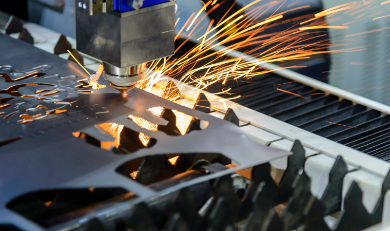
Ever wondered how a flat metal sheet transforms into a precision-engineered bracket for an aircraft or a decorative panel for a storefront? That transformation begins with custom metal plate cutting—a process that sits at the heart of modern metal fabrication.
Custom metal plate cutting is a specialized manufacturing process that shapes metal plates into precise components according to unique specifications, tolerances, and application requirements—delivering tailored solutions that standard off-the-shelf parts simply cannot provide.
Unlike grabbing a pre-made metal piece off the shelf, this process starts with your exact dimensions, your specific material choice, and your precise tolerance requirements. The result? Components that fit your application perfectly, every single time.
What Sets Custom Metal Plate Cutting Apart
Standard metal cutting typically involves producing large quantities of identical parts with general specifications. Custom metal cutting, however, flips this approach entirely. You're not adapting your project to available materials—the material adapts to your project.
Here's what makes this distinction matter:
- Precision-driven specifications: Tolerances are defined by your application needs, not manufacturing convenience
- Material flexibility: Choose from aluminum sheet, stainless steel, brass, copper, or specialty alloys based on performance requirements
- Design freedom: Complex geometries, intricate cutouts, and unique shapes become achievable
- Application-specific outcomes: Every cut considers the final use case, whether structural or aesthetic
This tailored approach serves industries where precision isn't optional—it's essential. Aerospace manufacturers rely on custom-cut components for aircraft frames and engine housings. Automotive companies need precisely dimensioned metal plates for chassis and body panels. Construction firms require structural elements cut to exact specifications. Even businesses ordering custom metal signs depend on accurate cuts for professional results.
From Raw Material to Precision Component
The journey from raw metal plate to finished component involves multiple critical stages. It begins with material selection—choosing the right metal type and thickness for your specific application. Next comes the design phase, where CAD files translate your vision into machine-readable instructions.
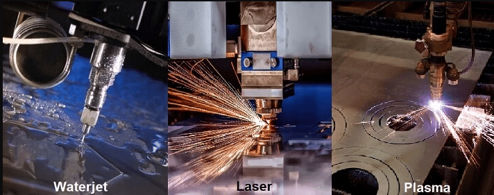
The actual metal cutting process then transforms that flat metal sheet into your specified shape using technologies like laser, waterjet, or plasma cutting. Finally, quality verification ensures the finished piece meets your dimensional and tolerance requirements.
Understanding these fundamentals positions you to make informed decisions throughout your ordering process. The following sections will guide you through cutting methods, material selection, and the practical details that separate successful projects from costly mistakes.
Cutting Methods Compared for Metal Plate Projects
Choosing the wrong cutting technology can cost you thousands in wasted material and delayed timelines. Yet most suppliers simply list their available methods without explaining which one actually fits your project. Let's change that.
Each cutting method brings distinct advantages—and limitations. Understanding these trade-offs helps you match the right technology to your specific requirements, whether you're prioritizing precision, speed, or budget.
| Cutting Method | Material Compatibility | Thickness Range | Precision Level | Edge Quality | Speed | Cost |
|---|---|---|---|---|---|---|
| Laser Cutting | Steel, stainless, aluminum, brass, copper | 0.5–25mm | ±0.1–0.13mm | Excellent (smooth, minimal burr) | Very Fast | Medium-High |
| Waterjet Cutting | All metals, stone, glass, composites | Up to 200mm+ | ±0.1–0.25mm | Good (no heat-affected zone) | Slow-Medium | High |
| Plasma Cutting | Conductive metals only | 3–150mm | ±1–2mm | Rough (requires finishing) | Very Fast | Low-Medium |
| CNC Routing | Softer metals (aluminum, brass, copper) | Up to 25mm | ±0.05–0.1mm | Good (machined finish) | Medium | Medium |
| Saw Cutting | All metals | Virtually unlimited | ±0.5–2mm | Rough (requires facing) | Fast | Low |
| Flame Cutting | Carbon steel primarily | 6mm–300mm+ | ±0.75–1.5mm | Rough (large heat-affected zone) | Medium | Low |
Laser Cutting for Precision and Speed
When your project demands intricate details and tight tolerances, a laser cutter becomes your best ally. The focused beam cuts metal with surgical precision—achieving tolerances around ±0.13mm (±0.005 inches) that few other methods can match.
Laser cutting excels in specific scenarios:
- Thin to medium materials: Optimal performance on sheets up to 12.7mm thick
- Complex geometries: Small holes, sharp corners, and detailed patterns
- Clean edges: Minimal post-processing required—parts often come ready for bending or assembly
- High-volume production: Fast cycle times reduce per-part costs
However, laser cutting has limitations. Efficiency decreases significantly with thicker materials, and highly reflective metals like copper require fiber lasers rather than CO₂ systems. The kerf—the width of material removed during cutting—is typically narrow (0.1–0.3mm), which matters when calculating final dimensions.
Understanding kerf is essential: if your metal cutter removes material during the cut, your final piece will be slightly smaller than the original outline unless compensated in the design file.
Waterjet vs Plasma for Thick Materials
Once material thickness exceeds what laser cutting handles efficiently, two technologies compete for your attention: waterjet and plasma. Each cuts metal through entirely different mechanisms, producing distinct results.
Waterjet cutting uses high-pressure water mixed with abrasive particles to erode material. This "cold" cutting process generates no heat, which means:
- No heat-affected zone (HAZ) that could alter material properties
- No warping or thermal distortion on thin or sensitive parts
- Ability to cut virtually any material—metals, stone, glass, composites
- Preservation of material hardness and temper
The trade-off? Speed and cost. Waterjet cutting runs 3–4 times slower than plasma on comparable materials, and operating costs are roughly double per linear foot.
Plasma cutting dominates when working with thick conductive metals while keeping costs manageable. If you're cutting 1-inch steel plate or thicker, plasma offers the best speed-to-cost ratio. It handles materials up to 150mm thick efficiently.
The downside involves edge quality. Plasma produces a rougher cut with a larger heat-affected zone. To define dross—the solidified molten metal that adheres to the cut edge—it's the slag-like residue that often requires grinding or secondary finishing. This makes plasma better suited for structural applications where ultra-fine edges aren't critical.
Choosing Between Them
- Choose waterjet when: Heat damage is unacceptable, material properties must remain unchanged, or you're cutting non-metals
- Choose plasma when: Speed and cost matter more than edge finish, working with thick steel, or parts will undergo additional processing anyway
CNC Routing, Saw Cutting, and Flame Cutting
These three methods round out your options, each serving specific niches:
CNC routing uses rotating cutting tools to remove material—similar to milling. It achieves excellent precision (±0.05–0.1mm) and produces machined surface finishes. Best for softer metals like aluminum and brass where you need precision without heat distortion. Unlike laser or plasma, CNC routing can also create 3D features, chamfers, and pockets.
Saw cutting remains the fastest and most economical method for straight cuts on stock preparation. Modern CNC band saws achieve ±0.1mm accuracy with automatic feeding. While edge quality is rough and usually requires facing, saw cutting handles virtually unlimited thickness ranges.
Flame cutting (also called oxy-fuel cutting) uses a torch and oxygen to cut through carbon steel. It's the go-to method for very thick steel plates—handling 300mm+ thicknesses that other methods can't touch. The significant heat-affected zone and rough edges limit its use to heavy structural applications where precision tolerances aren't critical.
Many fabrication shops combine multiple technologies. A common pairing: plasma or flame cutting for initial stock separation, followed by laser cutting for precision features. Understanding how these methods complement each other helps when discussing your project with fabricators. Later operations like mig vs tig welding or bending may also influence which cutting method works best—some processes require specific edge preparations or heat conditions.
Now that you understand what each cutting method offers, the next critical decision involves material selection. The metal you choose affects not just cutting method options but also tolerances, edge quality, and final part performance.
Choosing the Right Metal for Your Cutting Project
You've selected your cutting method—but have you considered how your material choice affects everything from edge quality to achievable tolerances? The metal you choose isn't just about final application requirements. It directly influences cutting speed, precision outcomes, and even which technologies work at all.
Each metal behaves differently under cutting forces and heat. Understanding these characteristics helps you avoid costly surprises and select materials that match both your performance needs and your fabrication process.
Aluminum and Steel Cutting Considerations
Aluminum and steel dominate custom metal plate cutting projects, yet they couldn't be more different under the cutter.
Aluminum sheet metal ranks among the easiest materials to cut. Its low hardness (typically 15–120 HB compared to steel's 150–300 HB) means less tool wear and faster processing. According to machining data from DWJ's CNC analysis, aluminum allows cutting speeds of 200–500 m/min—roughly 2–4 times faster than stainless steel.
- Thermal conductivity: Excellent (~200 W/m·K)—heat dissipates quickly, reducing distortion
- Chip formation: Short, brittle chips that clear easily from the cutting zone
- Edge quality: Clean cuts with minimal burring on most thicknesses
- Best cutting methods: Laser (thin sheets), waterjet (no heat distortion), CNC routing (precision features)
- Common grades: 6061-T6 for structural applications, 5052 for forming, 3003 for general purpose
An aluminum sheet typically allows larger depths of cut and higher feed rates, translating to shorter production times and lower per-part costs. Machining time for aluminum can be 2–4 times shorter than comparable stainless steel parts.
Steel plate offers superior strength but requires more aggressive cutting parameters and generates more heat. Carbon steel responds well to plasma and flame cutting, while stainless steel sheet demands more careful heat management.
- Thermal conductivity: Low (~15–50 W/m·K)—heat concentrates at the cut zone
- Work hardening: Stainless grades harden during cutting, affecting subsequent operations
- Edge quality: Varies significantly by cutting method and material grade
- Best cutting methods: Laser (thin to medium), plasma (thick carbon steel), waterjet (heat-sensitive applications)
- Cutting speeds: 50–120 m/min for milling, 80–150 m/min for turning—much slower than aluminum
The practical effect? A steel plate project often takes 2–3 times longer than the same geometry in aluminum, with higher tool wear costs factored in.
Working with Specialty Metals
Beyond the aluminum-steel decision, specialty metals like brass, copper, and bronze each bring unique cutting characteristics.
Brass cuts smoothly and produces excellent surface finishes, making it popular for decorative and precision applications. If you're wondering what is brass made of, it's an alloy of copper and zinc—the zinc content determines machinability. Higher zinc content (like in free-cutting brass C360) improves chip formation and cutting ease.
- Machinability: Excellent—often used as the benchmark for rating other metals
- Edge quality: Very clean cuts with minimal post-processing
- Laser compatibility: Requires fiber lasers due to reflectivity
- Applications: Musical instruments, decorative hardware, electrical components
When comparing brass vs bronze, remember that bronze contains copper and tin (sometimes with aluminum or other elements). Bronze is typically harder and more wear-resistant but less machinable than brass. Choose bronze for applications requiring corrosion resistance in marine environments or higher load-bearing capacity.
Copper sheet presents the most challenging cutting scenario among common metals. Its high reflectivity causes problems with CO₂ lasers, while its excellent thermal conductivity (nearly 400 W/m·K) rapidly dissipates cutting heat.
- Reflectivity: Requires fiber lasers or waterjet cutting—CO₂ lasers reflect dangerously
- Heat dissipation: Requires higher power input to maintain cutting temperatures
- Chip formation: Long, stringy chips that can tangle in machinery
- Best cutting methods: Waterjet (no heat issues), fiber laser (with proper setup), CNC routing
- Applications: Electrical busbars, heat exchangers, decorative elements
Understanding Gauge Thickness
Material thickness profoundly impacts cutting method selection and precision outcomes. Yet thickness specifications can be confusing—especially when gauge measurements enter the picture.
A gauge size chart translates gauge numbers to actual decimal thicknesses, but here's the critical detail: gauge thickness varies by material type. A 10-gauge aluminum sheet measures 0.102 inches, while 10-gauge stainless steel measures 0.135 inches—a difference of over 30%.
This variation traces back to the gauge system's origins in wire manufacturing during the 1800s. The gauge number originally indicated how many times a wire was drawn through reducing dies. Different metals compressed at different rates, creating unique gauge-to-thickness relationships for each material.
Key gauge thickness facts to remember:
- Higher gauge = thinner material (18 gauge is thinner than 14 gauge)
- Each metal has its own gauge chart—never assume cross-material equivalence
- Beyond ¼ inch: Materials are classified as plate rather than sheet and measured in decimals or fractions
- Example comparison: 12 gauge mild steel measures 0.105" while 12 gauge aluminum measures 0.081"
For precision projects, always specify thickness in decimal inches or millimeters rather than gauge numbers. This eliminates conversion errors and ensures you receive exactly what your design requires.
How does thickness affect your cutting options? Thinner materials (under 6mm) work well with laser cutting for maximum precision. Medium thicknesses (6–25mm) open up plasma and waterjet options. Very thick plates (25mm+) typically require waterjet, plasma, or flame cutting—with precision tolerances widening as thickness increases. The next section breaks down these relationships in detail, showing exactly which tolerances you can expect from each combination of material and cutting method.
Thickness Ranges and Precision Tolerances Explained
So you've picked your material and understand the cutting methods available. But here's the question most suppliers never answer clearly: what thickness can each method actually handle, and how precise will your finished parts be?
These two factors—thickness capacity and achievable tolerances—determine whether your project succeeds or fails. Let's break down both in practical terms you can actually use when placing orders.
Thickness Limits by Cutting Method
Each cutting technology has a "sweet spot" where it performs optimally, plus upper limits where cutting becomes impractical or impossible. The following table shows what to expect across common materials and methods, based on industry machining data:
| Cutting Method | Carbon/Mild Steel | Stainless Steel | Aluminum | Typical Tolerance |
|---|---|---|---|---|
| Laser Cutting (Fiber) | Up to 30mm | Up to 25mm | Up to 20mm | ±0.1–0.13mm |
| Laser Cutting (CO₂) | Up to 25mm | Up to 20mm | Up to 15mm | ±0.1–0.15mm |
| Plasma Cutting | Up to 150mm | Up to 38mm | Up to 38mm | ±1–2mm |
| Waterjet Cutting | Up to 150mm+ | Up to 150mm+ | Up to 150mm+ | ±0.1–0.25mm |
| Flame/Oxy-Fuel | 5mm–300mm | Not suitable | Not suitable | ±0.75–1.5mm |
| Mechanical Shearing | Up to 25mm | Up to 20mm | Up to 25mm | ±0.5–1mm |
Notice something important? Laser cutting excels below 10mm where it delivers both speed and precision. But push beyond 20–25mm, and you're forced toward plasma or waterjet regardless of precision requirements.
Wondering how thick is 16 gauge steel in this context? At 1.5mm (0.060"), 16 gauge thickness falls squarely in laser cutting's optimal range. Similarly, 14 gauge steel thickness measures 1.9mm (0.075")—still ideal for laser processing. A sheet metal gauge chart helps translate these gauge sizes into decimal measurements, but the key takeaway is simple: thin sheet metals work beautifully with laser cutting, while thicker plates demand alternative methods.
For reference, 11 gauge steel thickness measures approximately 3mm (0.120"), still well within laser cutting capabilities but approaching the range where plasma becomes cost-competitive for simpler cuts.
Understanding Tolerance Specifications
Tolerances tell you how much your finished part dimensions can vary from the specified size. But what do these numbers actually mean for your project?
Imagine you need a bracket with a 100mm length:
- ±0.1mm tolerance: Final length will measure 99.9–100.1mm (laser/waterjet quality)
- ±1mm tolerance: Final length will measure 99–101mm (plasma cutting quality)
- ±1.5mm tolerance: Final length will measure 98.5–101.5mm (flame cutting quality)
That ±0.1mm laser tolerance means your part could vary by the thickness of a human hair. The ±1.5mm flame cutting tolerance? That's roughly the width of a pencil lead—fine for structural steel, problematic for precision assemblies.
When Tolerance Actually Matters
Here's practical guidance on matching tolerances to applications:
- ±0.1–0.15mm: Required for mating parts, press fits, precision assemblies, aerospace components
- ±0.25–0.5mm: Acceptable for general fabrication, enclosures, brackets with standard fastener holes
- ±1–2mm: Suitable for structural components, parts receiving secondary machining, rough stock preparation
The critical insight? Specifying tighter tolerances than you actually need wastes money. If your steel plate gets welded into a structural frame, paying premium prices for ±0.1mm laser precision makes little sense when ±1mm plasma cuts would perform identically in the final application.
Understanding these thickness and tolerance relationships helps you communicate clearly with fabricators. But translating your design into the files and specifications they need? That requires knowing exactly what information to provide—which brings us to preparing your design files for custom cutting.
Preparing Your Design Files for Custom Cutting
You've selected your cutting method, chosen the right material, and understand what tolerances you need. Now comes the step that trips up more projects than any other: getting your design files right the first time.
Incomplete or incorrectly formatted files cause delays, miscommunication, and costly revisions. Whether you're ordering a custom cut steel sheet for an industrial application or sheet metal cut to size for a prototype, proper file preparation separates smooth orders from frustrating back-and-forth exchanges.
Follow this step-by-step checklist to prepare your custom cutting order:
- Create your design in vector format: Use software like Adobe Illustrator, AutoCAD, CorelDRAW, or Inkscape. Raster images (JPG, PNG) cannot be used directly—they must be traced and converted to vectors first.
- Export to accepted file formats: DXF and DWG files work best for most fabricators. STEP files (.stp) provide comprehensive 3D data when needed. AI files (Adobe Illustrator) are acceptable at some shops.
- Convert all text to outlines or shapes: Editable text boxes cause font substitution errors. In Illustrator, use "Create Outlines." In CAD software, use "Explode" or "Expand."
- Verify dimensions at 1:1 scale: Print your design at 100% scale to confirm measurements match your intent—especially important if you converted from a raster file.
- Remove duplicate cut lines: Overlapping lines cause the laser or cutter to pass multiple times, degrading edge quality and increasing costs. According to Webelektron's laser cutting guidelines, duplicate lines create significantly thicker, lower-quality cutting edges.
- Specify material type, grade, and thickness: Include exact specifications—not just "aluminum" but "6061-T6 aluminum, 3mm thick."
- Add tolerance callouts: Mark critical dimensions with required tolerances (e.g., 50.00 ±0.10mm).
- Include part numbers and revision status: Part names alone cause confusion when shops handle multiple similar projects. Add unique identifiers and document any revisions in both the title block and revision block.
- Specify finish and edge quality requirements: Note if you need deburring, specific surface finishes, or grain direction for cosmetic applications.
- Organize cut lines on separate layers: Place cutting paths on a dedicated layer, clearly labeled. Use different colors or layers for engraving, scoring, or reference annotations.
File Formats and Design Requirements
Not all file formats communicate your design intent equally well. Here's what each format delivers:
- DXF (Drawing Exchange Format): The industry standard for 2D cutting files. Compatible with virtually all laser, plasma, and waterjet systems. Transfers geometric data accurately but doesn't carry material or tolerance specifications—add these separately.
- DWG: AutoCAD's native format, carrying more detail than DXF. Preferred when your design includes layers, annotations, and dimensional data.
- STEP (.stp): Essential for 3D models and complex assemblies. Allows fabricators to verify design intent and check manufacturability before cutting begins.
- AI (Adobe Illustrator): Works well for simpler designs and custom cut sheet metal projects with artistic elements. Ensure you export with "hairline" stroke widths for cut paths.
Wondering how to cut sheet metal accurately from your design? The answer starts with these file fundamentals. Per SendCutSend's laser cutting guidelines, files converted from raster images require careful dimension verification—printing at 100% scale helps confirm your measurements before ordering.
Specifying Dimensions Correctly
Clear dimension notation prevents costly misinterpretations. Follow these practices:
- Use decimal inches or millimeters consistently: Don't mix measurement systems within a single drawing. Specify which system you're using.
- Call out critical dimensions explicitly: Don't rely on fabricators to scale from your drawing. Mark key measurements directly.
- Indicate hole sizes and positions: Specify hole diameters and their center-point locations from reference edges.
- Note grain direction when relevant: For cosmetic finishes or parts requiring specific mechanical properties, mark the required grain orientation. Most shops default to left-to-right across the print.
- Specify hardware by manufacturer name and part number: Internal naming conventions can cause confusion—Approved Sheet Metal recommends providing the exact manufacturer information to ensure correct sourcing.
For finishing requirements, don't leave shops guessing. If you need powder coating, specify the color, manufacturer, and finish type (matte, gloss, textured). If edge quality matters for your application, state whether you need deburred edges, chamfers, or specific surface roughness values.
With properly prepared files, your custom cut order moves smoothly from quote to production. But even experienced buyers make mistakes that delay projects and inflate costs—the next section covers the most common pitfalls and how to avoid them.
Common Ordering Mistakes and How to Avoid Them
You've prepared your files, selected your material, and specified your tolerances. Everything looks ready—until a preventable mistake derails your timeline and budget. The frustrating truth? Most custom metal plate cutting delays stem from errors that buyers make before production even begins.
Understanding these pitfalls before you order saves weeks of back-and-forth communication and prevents costly rework. Here are the most frequent ordering mistakes and exactly how to avoid each one.
- Submitting incompatible file formats: Raster images like JPGs or PNGs don't contain precise dimension data. Fabricators need vector-based files (DXF, DWG, AI, or SVG) to generate accurate cut paths. Consequence: Your order stalls while you recreate files from scratch.
- Ignoring kerf allowances: The laser or plasma beam removes material during cutting—typically 0.1–0.4mm depending on the method and material. Designing parts with zero clearance for slots, tabs, or interlocking features means pieces won't fit together as intended. Consequence: Assembled components bind, gap, or require manual modification.
- Specifying unnecessarily tight tolerances: Requesting ±0.1mm precision when ±0.5mm would work perfectly for your application inflates costs significantly. Consequence: You pay premium prices for precision that provides zero functional benefit.
- Overlooking scale and unit errors: A design that appears as 10mm in your CAD software might be interpreted as 10 inches by the cutting machine if units aren't specified correctly. Consequence: Unusable parts that are dramatically wrong in size.
- Selecting unsuitable materials: Choosing a metal too soft for structural loads or too hard for your intended forming operations leads to premature failure or fabrication problems. Consequence: Parts that warp, crack, or can't be processed as planned.
- Underestimating lead times: Custom cut metals require machine setup, nesting optimization, and quality verification. Additional processing like bending or finishing adds more time. Consequence: Project delays when parts arrive later than expected.
- Leaving duplicate cut lines in files: Overlapping paths cause the cutter to pass multiple times over the same location. According to 1CutFab's ordering guide, this degrades edge quality and increases processing time. Consequence: Poor edge finish requiring additional cleanup, plus higher costs.
- Ordering single pieces when bulk makes sense: Per-unit costs drop significantly with quantity. Shops optimize nesting to reduce material waste on larger orders. Consequence: Paying more per piece of metal than necessary when you'll need additional parts later.
Specification Errors That Delay Projects
Tolerance and dimension errors cause the longest delays because they often aren't discovered until fabrication begins—or worse, after parts arrive.
The most damaging specification mistakes include:
- Missing tolerance callouts on critical dimensions: Without explicit tolerances, fabricators apply standard shop tolerances that may not meet your requirements. Always mark critical features with specific tolerance values.
- Failing to specify material grade: "Aluminum" isn't a complete specification. 6061-T6 machines differently than 5052-H32, and the wrong grade affects both fabrication success and end-use performance.
- Omitting finish requirements: If edge quality matters for your application, state it explicitly. Otherwise, you receive whatever finish the cutting process naturally produces—which may include burrs, dross, or heat discoloration.
- Not communicating assembly relationships: When custom metal shapes must mate with other components, sharing assembly context helps fabricators understand which dimensions are truly critical versus which have flexibility.
According to Kirmell's analysis of laser cutting errors, even professional laser cutting machines have typical tolerances around ±0.1mm. If your design has critical dimensions tighter than this, communicate them clearly and confirm the fabricator can achieve them before ordering.
Material Selection Pitfalls to Avoid
Choosing the wrong material for your application causes problems that no amount of precision cutting can fix.
Watch for these common material selection errors:
- Ignoring environmental exposure: A cut metal sheet destined for outdoor use requires different material considerations than indoor components. Carbon steel rusts without protective coatings; aluminum and stainless steel offer inherent corrosion resistance.
- Overlooking downstream processing: If your parts require welding, bending, or forming after cutting, verify your material choice supports these operations. Some alloys work-harden during cutting, making subsequent bending difficult.
- Selecting thickness without considering weight: Thicker material adds strength but also mass. For weight-sensitive applications like automotive or aerospace, balance structural requirements against weight constraints.
- Assuming availability: Specialty alloys and unusual thicknesses may require extended lead times. Benchmark Steel recommends checking material availability before finalizing your design to avoid delays.
The prevention strategy for most ordering mistakes is straightforward: communicate clearly, verify specifications twice, and ask questions before submitting rather than after problems emerge. With common pitfalls identified, the next step is matching the right cutting method to your specific project requirements—a decision framework that balances precision, budget, and timeline considerations.
Selecting the Right Cutting Method for Your Project
You understand the cutting technologies. You know which materials work with each method. You've even learned the tolerance ranges to expect. But here's the real challenge: how do you pull all these factors together into a single, confident decision?
Most fabrication shops simply list their capabilities and leave the selection to you. That approach works fine if you're an experienced engineer—but what if you're ordering custom metal plate cutting for the first time? This section provides the decision framework you need to match your specific project requirements to the right cutting technology.
Matching Methods to Project Requirements
Selecting the optimal cutting method comes down to five key factors working together: material type, thickness, precision requirements, budget constraints, and turnaround time. Each factor narrows your options until the right choice becomes clear.
Consider a practical scenario. You need 50 steel brackets, each 6mm thick, with ±0.15mm tolerance on mounting holes. You have three weeks and a moderate budget. Walking through the decision factors:
- Material: Carbon steel—compatible with laser, plasma, waterjet, and flame cutting
- Thickness: 6mm—well within laser cutting's optimal range
- Precision: ±0.15mm—achievable with laser or waterjet, too tight for plasma
- Volume: 50 pieces—benefits from laser's fast cycle times
- Timeline: Three weeks—comfortable for most sheet metal fabrication shops
The answer? Laser cutting emerges as the clear winner—delivering the required precision at competitive speeds without waterjet's higher operating costs.
Now imagine the same project but with 25mm thickness. Suddenly laser cutting becomes impractical, plasma can't hit your tolerance, and waterjet becomes the only viable option despite its higher cost. Material thickness alone shifted the entire decision.
The following decision matrix maps common project scenarios to recommended cutting methods, helping you navigate these trade-offs systematically:
| Project Scenario | Recommended Method | Why This Choice | Alternative Options |
|---|---|---|---|
| Thin sheet (<6mm), tight tolerances, complex shapes | Laser Cutting | Best precision, fastest processing, clean edges | Waterjet (if heat-sensitive) |
| Medium plate (6-20mm), standard tolerances, high volume | Laser Cutting | Excellent speed-to-precision balance | Plasma (if budget-constrained) |
| Thick steel (20-50mm), structural applications | Plasma Cutting | Fast processing, cost-effective, handles thickness | Waterjet (if precision critical) |
| Very thick plate (50mm+), heavy structural | Flame/Plasma Cutting | Only practical options at this thickness | Waterjet (if tolerances demand it) |
| Heat-sensitive materials or alloys | Waterjet Cutting | No heat-affected zone, preserves material properties | Fiber laser (with careful parameters) |
| Reflective metals (copper, brass) | Fiber Laser or Waterjet | CO₂ lasers reflect dangerously from these surfaces | CNC routing (for thinner gauges) |
| Prototype/one-off parts, quick turnaround | Laser or Waterjet | Minimal setup time, no tooling required | Plasma (for thicker materials) |
| High-volume production, simple shapes | Laser or Plasma Cutting | Maximum throughput, lowest per-part cost | Stamping (if volume justifies tooling) |
Budget vs Precision Trade-offs
Here's the uncomfortable truth about custom fabrication: precision costs money. Every step tighter in tolerance specification increases your per-part expense—sometimes dramatically.
According to Zintilon's fabrication analysis, the selection process must consider complete economic factors beyond per-cut costs. This includes setup time, material waste from kerf, potential secondary operations like deburring, and equipment availability.
Understanding these trade-offs helps you optimize spending:
- Plasma vs. Laser: Plasma cutting costs roughly 30-50% less per linear foot than laser on materials over 10mm. If your steel fabrication project has ±1mm tolerance requirements, plasma delivers acceptable quality at significant savings.
- Waterjet vs. Everything Else: Waterjet cutting runs 2-3x the operating cost of laser or plasma. Reserve it for applications where zero heat distortion is mandatory or when cutting materials other technologies can't handle.
- Setup Fees vs. Volume: Most fabrication shops charge setup fees that get amortized across your order quantity. Ordering 100 pieces versus 10 pieces might only increase your total cost by 40%—not 10x.
For metal fab projects balancing budget constraints against quality requirements, consider this approach: specify your minimum acceptable tolerance rather than your ideal tolerance. If ±0.5mm works for your application, don't request ±0.1mm simply because it sounds more precise.
When searching for metal fabricators near me or exploring local fabrication shops, come prepared with your project specifications organized by priority. Knowing which requirements are firm versus flexible allows fabricators to suggest cost-saving alternatives you might not have considered.
For example, a fabricator might recommend plasma cutting for your outer profiles (where ±1mm tolerance is acceptable) and laser cutting only for your precision mounting holes. This hybrid approach delivers required precision where it matters while controlling costs on less critical features.
The right cutting method isn't always the most precise or the cheapest—it's the one that satisfies your actual requirements at the best value. With your cutting method selected, the next consideration becomes understanding the pricing factors that determine your final project cost.
Understanding Pricing and Cost Optimization
You've selected your cutting method and material. You understand tolerances and have your design files ready. Now comes the question everyone wants answered upfront: how much to get a metal part made?
The honest answer? It depends on multiple interconnected factors. But understanding what drives costs—and which factors you can control—helps you budget accurately and identify legitimate savings opportunities without sacrificing quality.
What Drives Custom Cutting Costs
Not all cost factors carry equal weight. Here's what impacts your final price, listed from most to least significant:
- Material type and grade: Raw material costs vary dramatically. According to 1CutFab's pricing analysis, steel runs $0.50–$1.50 per pound, aluminum $2.00–$3.50, stainless steel $2.50–$5.00, and brass or copper $3.00–$7.00 per pound. Exotic metals like titanium cost even more due to sourcing difficulty.
- Material thickness: Thicker plates require more cutting time, higher energy consumption, and often different (more expensive) cutting technologies. A 25mm steel plate costs significantly more to process than a 3mm sheet.
- Cutting method selected: Laser cutting typically costs less than waterjet for comparable materials. Plasma offers the most economical option for thick conductive metals. Your precision requirements often dictate which method—and cost tier—applies.
- Design complexity: Intricate shapes, small cutouts, and detailed patterns slow cutting speed. More inches of cutting path equals higher cost. Fine details require slower processing to maintain edge quality.
- Order quantity: Setup and programming costs get spread across more units with larger orders. LTJ Industrial's fabrication guide confirms that larger batches significantly reduce per-unit pricing through economies of scale.
- Tolerance requirements: Tighter tolerances demand slower cutting speeds, additional quality checks, and sometimes more expensive cutting methods. Standard tolerances cost less than precision specifications.
- Finishing and post-processing: Services like powder coating, anodizing, or deburring add to your total. Expect $1–$5 per bend for forming operations. Surface treatments like powder coat finishes vary by complexity and part size.
- Turnaround time: Rush orders incur premiums due to overtime labor, expedited scheduling, and faster shipping. Planning ahead saves money.
- Setup fees: Small orders may face minimum charges for programming and machine setup. These fees matter less as quantity increases.
- Shipping and handling: Larger or heavier parts cost more to ship. Geographic distance from your fabricator adds transportation expenses.
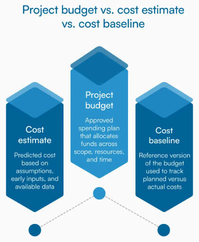
Optimizing Your Project Budget
Understanding cost drivers is one thing—leveraging that knowledge to optimize spending is another. Here's how to get maximum value from your custom metal plate cutting budget.
Simplify designs where possible. Every unnecessary cutout, tight corner, or complex curve adds cutting time. If a simpler shape serves the same function, your quote drops accordingly. Ask yourself: does this feature add functional value, or can it be eliminated?
Specify appropriate tolerances. Don't request ±0.1mm precision when ±0.5mm works for your application. Over-specifying tolerances forces fabricators into slower, more expensive processes without delivering meaningful benefit.
Consider material substitutions. Sometimes switching from stainless steel to aluminum—or from specialty alloys to standard grades—delivers equivalent performance at lower cost. Discuss alternatives with your fabricator before finalizing specifications.
Batch orders strategically. If you'll need additional parts later, ordering everything at once spreads setup costs and unlocks volume discounts. Many steel fabricators offer significant price breaks at quantity thresholds.
Plan finishing requirements upfront. Need anodizing or powder coating services? Specifying these during quoting rather than as afterthoughts often reduces costs through streamlined processing.
Get quotes quickly and compare. When evaluating fabrication shops near me or metal fabrication near me options, fast quote turnaround matters. Manufacturers offering rapid response—like Shaoyi's 12-hour quote turnaround for automotive stamping projects—help you compare options quickly and keep projects moving. Their 5-day rapid prototyping capability also enables faster design validation, reducing overall project timelines and associated costs.
What Fabricators Need for Accurate Quotes
Incomplete quote requests generate incomplete estimates—or delays while fabricators chase missing information. Provide these details upfront:
- Complete design files in vector format (DXF, DWG, or STEP)
- Material type, grade, and thickness specifications
- Quantity required, including any volume tier options you want quoted
- Tolerance requirements for critical dimensions
- Finish specifications (deburring, coating, surface treatment)
- Delivery timeline and location
- Whether you're supplying material or need the fabricator to source it
The more complete your initial request, the more accurate your quote. This prevents the frustrating scenario where your "final" quote increases after the fabricator discovers requirements that weren't in the original specification.
With pricing factors understood and your budget optimized, one critical question remains: how do you verify that finished parts actually meet your specifications? The final section covers quality standards, certifications, and inspection processes that ensure your custom cutting project delivers exactly what you ordered.
Quality Standards and Verification for Custom Parts
Your order ships. Parts arrive at your facility. But here's the question that separates successful projects from costly failures: how do you know what you received actually meets your specifications?
Quality verification isn't just about measuring finished parts—it starts with understanding what quality standards mean, which certifications matter, and how professional fabricators ensure consistency throughout production. This knowledge helps you evaluate suppliers, interpret inspection reports, and verify parts yourself when they arrive.
Industry Quality Certifications Explained
Certifications tell you more than whether a fabricator passed an audit. They indicate systematic approaches to quality management, documented processes, and consistent manufacturing capability. But not all certifications carry equal weight for every application.
ISO 9001 serves as the foundation for quality management systems across manufacturing industries. According to Metal Cutting Corporation's quality control guide, ISO 9001 certification means the fabricator has documented processes, established quality objectives, and maintains systems for continuous improvement. For general custom metal plate cutting projects, ISO 9001 certification provides reasonable assurance of consistent quality.
IATF 16949 takes quality management further—specifically for automotive applications. As Xometry's certification analysis explains, this framework builds on ISO 9001 with automotive-specific requirements for defect prevention, variation reduction, and waste elimination throughout the supply chain. IATF 16949 certification signals a manufacturer's capability to produce precision components for demanding applications like chassis, suspension, and structural parts.
What does IATF 16949 certification actually mean for your project? It indicates:
- Documented manufacturing processes: Every step from material receipt to final inspection follows written procedures
- Statistical process control: Production parameters are monitored continuously, not just at inspection points
- Defect prevention focus: Systems identify and address potential quality issues before they affect parts
- Traceability requirements: Materials and processes can be traced throughout production
- Customer-specific requirements: Capability to meet individual automotive OEM specifications
For precision metal cutting projects involving stainless steel plates, aluminum plate components, or other materials destined for automotive or aerospace applications, working with IATF 16949-certified manufacturers—like Shaoyi (Ningbo) Metal Technology—provides confidence that quality systems match the demands of your application.
Inspection and Verification Processes
Professional fabricators don't wait until production ends to check quality. Effective quality control integrates inspection throughout the manufacturing process, catching variations before they compound into defective parts.
Here are the critical quality checkpoints in a well-managed custom cutting operation:
- Material verification: Incoming steel plates, 316 stainless steel sheets, or aluminum stock gets inspected against purchase specifications. This includes checking material certifications, verifying chemical composition for critical applications, and inspecting for surface defects before cutting begins.
- First article inspection: The initial piece from any production run receives comprehensive dimensional verification. If the first part meets specifications, subsequent parts from the same setup should also conform—assuming consistent process control.
- In-process monitoring: According to OkDor's QC checkpoint analysis, effective process monitoring tracks cutting parameters, tool condition, and dimensional accuracy at regular intervals. This catches drift before it affects part quality.
- Tool condition checks: Cutting tools wear during production, gradually affecting dimensions and edge quality. Scheduled tool inspections and replacements prevent wear from pushing parts out of tolerance.
- Dimensional verification: Critical features get measured using calibrated instruments—micrometers, calipers, coordinate measuring machines (CMMs), or optical comparators depending on tolerance requirements.
- Surface finish assessment: Visual and instrumental inspection confirms edge quality, surface roughness, and absence of defects like burrs or heat discoloration.
- Final inspection: Before shipping, a sampling plan verifies the entire lot meets specifications. Most fabricators use Acceptable Quality Level (AQL) sampling—inspecting a statistically valid portion of parts to confirm lot quality.
- Documentation review: Complete records accompany finished parts, including material certifications, inspection data, and any deviation reports.
Verifying Parts When They Arrive
Even with certified suppliers and documented quality processes, incoming inspection at your facility provides final confirmation that parts meet your requirements.
For stainless steel sheet metal components, custom metal plate parts, or any precision-cut materials, follow these verification steps:
- Compare against drawings: Verify critical dimensions match your specifications. Use calibrated measuring tools appropriate for your tolerance requirements.
- Check material certifications: Review mill test reports or material certificates to confirm you received the specified grade and composition.
- Inspect edge quality: Examine cut edges for burrs, dross, or heat-affected zones that might impact assembly or performance.
- Verify quantity and labeling: Confirm part counts match your order and parts are properly identified with part numbers and revision levels.
- Document any issues immediately: If parts don't conform, photograph discrepancies and contact your supplier before proceeding with assembly or further processing.
Understanding tolerances in practical terms helps during this verification. Remember: a ±0.1mm tolerance on a 100mm dimension means acceptable parts measure between 99.9mm and 100.1mm. Measure several features on multiple parts—not just one dimension on one piece—to get a representative picture of lot quality.
Quality verification ultimately protects your investment in custom metal plate cutting. By understanding certifications, inspection processes, and verification techniques, you ensure that precision components arrive ready for their intended application—whether that's structural steel plates for construction, stainless steel plates for food processing equipment, or precision aluminum components for aerospace assemblies.
Frequently Asked Questions About Custom Metal Plate Cutting
1. How to cut a metal plate at home?
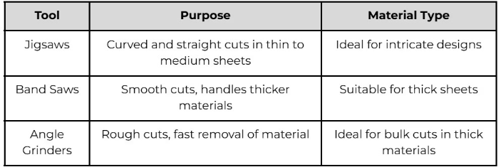
For thin metal plates at home, tin snips work well for straight cuts on materials under 1mm thick. For thicker materials, angle grinders with cutting discs or jigsaws with metal-cutting blades offer more capability. However, home cutting lacks the precision of professional methods—tolerances typically exceed ±2mm versus ±0.1mm from laser cutting. For precision parts or complex shapes, professional custom metal plate cutting services deliver superior results with proper edge quality and dimensional accuracy.
2. How much does metal laser cutting cost?
Laser cutting steel generally costs $13-$20 per hour of machine time. Your actual cost depends on cutting speed (typically 70 inches per minute for thin steel), material thickness, and design complexity. For example, 15,000 inches of cutting at standard speeds equals roughly 3.5 hours of active cutting. Additional factors include material costs ($0.50-$1.50/lb for steel), setup fees, and finishing requirements like deburring or powder coating. Request quotes with complete specifications to get accurate pricing.
3. How much does custom sheet metal fabrication cost?
Custom sheet metal fabrication averages $1,581 per project, ranging from $418 to $3,018 depending on complexity. Per-square-foot costs range from $4 to $48 based on material type and customization level. Key cost drivers include material grade (stainless costs 3-5x more than mild steel), cutting method selection, tolerance requirements, and finishing services. Larger orders reduce per-unit costs through setup fee distribution. Working with manufacturers offering rapid quote turnaround helps you compare options efficiently.
4. What is the most precise metal cutting method?
Laser cutting achieves the highest precision for most applications, with tolerances of ±0.1-0.13mm on materials up to 25mm thick. Waterjet cutting matches this precision (±0.1-0.25mm) while adding the benefit of zero heat-affected zone—critical for heat-sensitive alloys. CNC routing offers ±0.05-0.1mm tolerance on softer metals. Your choice depends on material type, thickness, and whether heat distortion is acceptable. For automotive-grade precision, IATF 16949-certified manufacturers ensure consistent quality.
5. What file formats do metal cutting services accept?
Most custom metal cutting services accept DXF and DWG files as industry standards for 2D cutting paths. STEP files work best for 3D models and complex assemblies. Adobe Illustrator (AI) files suit simpler designs. Critical requirements include vector-based formats (not raster images like JPG), text converted to outlines, no duplicate cut lines, and dimensions at 1:1 scale. Always specify material type, thickness, tolerances, and finish requirements separately from your design file.