 Small batches, high standards. Our rapid prototyping service makes validation faster and easier —

Laser Cutting Sheet Metal: Fiber Vs CO2 And When Each Wins
Understanding Laser Cutting Technology for Sheet Metal
Ever wondered how manufacturers create those perfectly precise metal components you see in everything from smartphones to aircraft? The answer lies in laser cutting sheet metal—a precision thermal process that has revolutionized modern manufacturing. This technology uses focused light beams to cut through metal materials with exceptional accuracy, achieving tolerances as tight as ±0.1 mm to ±0.5 mm.
Whether you're searching for metal fabrication near me or exploring options for your next project, understanding this technology is essential. It has become the industry standard for sheet metal fabrication, steadily replacing older mechanical methods that simply cannot match its capabilities.
The Science Behind Precision Light-Based Metal Cutting
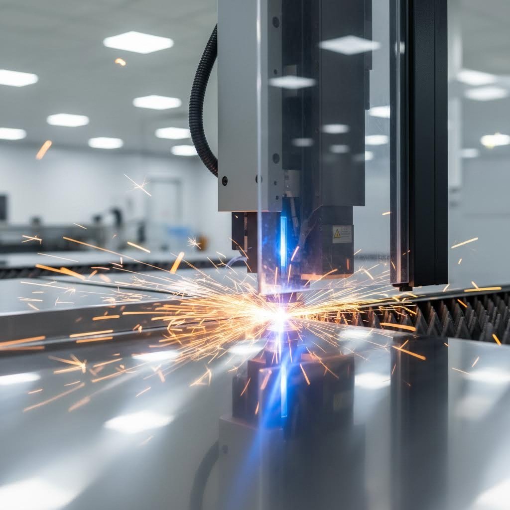
At its core, a laser cutter operates on a straightforward principle. A high-powered laser beam focuses intensely on a metal surface, generating enough energy to melt, burn, or vaporize the material along a programmed path. The process is controlled by CNC (Computer Numerical Control) systems that guide the beam with remarkable precision.
Think of it like using a magnifying glass to focus sunlight—except exponentially more powerful and precisely controlled. The concentrated light energy transforms solid metal into liquid or gas in milliseconds, creating clean cuts without physical contact between the tool and workpiece. This non-contact nature means there's minimal wear on equipment and no mechanical force distorting delicate materials.
Why Manufacturers Choose Laser Over Traditional Methods
Why has this technology become the go-to choice for fabrication shops near me and major manufacturers alike? The advantages are compelling:
- Exceptional precision: Laser cutting handles complex designs and tight tolerances that mechanical methods struggle to achieve
- Versatility: One machine can switch between different metals without changing tools
- Speed and efficiency: Automated operation dramatically reduces production time
- Reduced material waste: Clean, accurate cuts minimize discarded material
- Lower energy consumption: Compared to plasma cutting and other methods, laser cutting uses less energy while delivering greater precision
Laser cutting technology has become an integral part of modern manufacturing due to its high precision and efficiency—transforming how industries from automotive to aerospace approach metal fabrication.
Throughout this guide, you'll discover the key differences between fiber and CO2 lasers, learn which materials work best with each technology, and master design considerations that optimize your results. By the end, you'll understand exactly when each laser type wins—and how to make the smartest choice for your specific metal fabrication needs.
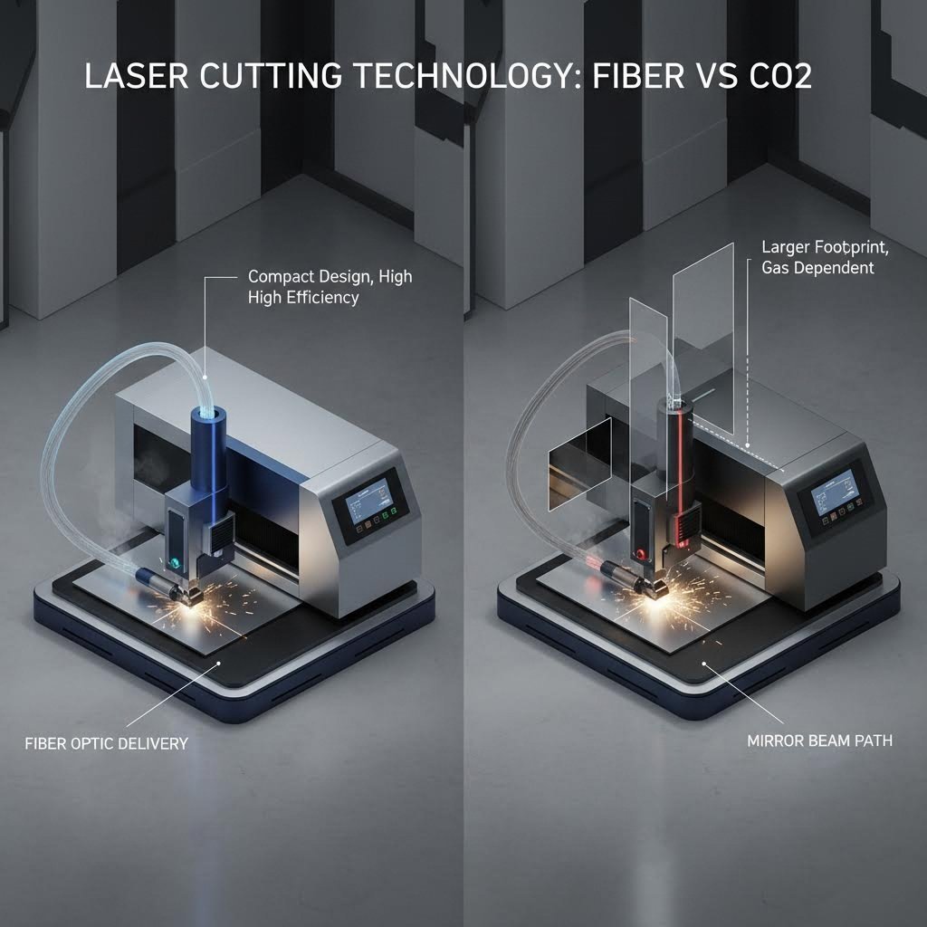
Fiber Lasers vs CO2 Lasers for Metal Cutting
So you understand how laser cutting works—but which laser type should you actually choose? This is where things get interesting. The two dominant technologies in the metal laser cutter market, fiber lasers and CO2 lasers, each bring distinct strengths to the table. Understanding their differences isn't just technical trivia; it directly impacts your cutting speed, operating costs, and the quality of your finished parts.
The fundamental difference starts at the wavelength level. Fiber lasers operate at approximately 1.06 microns, while CO2 lasers work at 10.6 microns. Why does this matter? Because different metals absorb laser energy differently based on wavelength. This single factor influences everything from which materials you can cut efficiently to how much power you'll consume during operation.
| Feature | Fiber Laser | CO2 Laser |
|---|---|---|
| Wavelength | 1.06 μm | 10.6 μm |
| Power Efficiency | ~30-35% electrical-to-optical conversion | ~10-20% electrical-to-optical conversion |
| Maintenance Requirements | Minimal—solid-state design with no consumables or mirror alignment | Higher—requires regular mirror alignment, gas refills, and consumable replacement |
| Best-Suited Materials | Stainless steel, aluminum, copper, brass, reflective metals | Thick mild steel, non-metals (plastics, wood, acrylic) |
| Cutting Speed (Thin Metals <6mm) | 2-3x faster than CO2 | Slower on thin materials |
| Cutting Speed (Thick Metals >10mm) | Competitive but may produce rougher edges | Smoother cuts on thick steel |
| Initial Investment | Higher upfront cost | Lower initial purchase price |
| Operating Cost | Uses approximately 1/3 the power of CO2 | Higher electricity and consumable costs |
Fiber Laser Advantages for Reflective Metals
Here's where fiber technology truly shines—literally. When you're laser cutting aluminum, copper, or brass, the 1.06-micron wavelength of a fiber laser cutter for metal is absorbed far more efficiently than the longer CO2 wavelength. Traditional CO2 lasers struggled with these reflective surfaces because much of the beam energy would bounce back, potentially damaging the laser optics and producing inconsistent cuts.
Modern fiber lasers have largely eliminated this problem. Their solid-state design delivers the beam through fiber-optic cables rather than mirrors, making them inherently more robust when processing reflective materials. The results speak for themselves:
- Stainless steel: Clean cuts up to 12mm thickness with superior edge quality
- Aluminum: Efficient processing up to 8mm with excellent precision
- Brass and copper: Reliable cutting up to 5mm—materials that would challenge older CO2 systems
For high-volume sheet metal operations, the speed advantage is remarkable. A cnc fiber laser cutting machine can cut thin materials 2-3x faster than its CO2 counterpart while consuming roughly one-third of the operating power. This efficiency translates directly to lower per-part costs and faster production cycles. Many shops find that fiber lasers pay for themselves within 2-3 years through reduced energy bills and increased throughput alone.
Even compact options like a desktop fiber laser have become viable for smaller operations focused on precision metal work, making this technology accessible beyond large industrial settings.
When CO2 Lasers Still Make Sense
Does this mean CO2 technology is obsolete? Not quite. A co2 laser cut metal machine still holds significant advantages in specific scenarios that many manufacturers encounter regularly.
Consider thick steel plates exceeding 15mm. While fiber lasers can technically cut these materials, CO2 lasers often produce smoother edge quality on very thick sections. The longer wavelength interacts differently with the material at greater depths, sometimes resulting in cleaner cuts that require less post-processing.
The real strength of CO2 lasers, however, lies in versatility. If your shop handles mixed materials—metal one day, acrylic signage the next, leather goods after that—a cnc laser cutting machine with CO2 technology offers flexibility that fiber simply cannot match. The 10.6-micron wavelength cuts non-metals beautifully, making it ideal for workshops serving diverse customer needs.
Budget considerations also play a role. While operating costs favor fiber lasers, the initial purchase price for CO2 equipment remains lower. For shops with occasional metal cutting needs or those just entering the laser metal cutting machine market, CO2 offers a more accessible entry point.
The practical takeaway? Many successful fabrication operations now run both technologies side by side—using fiber for daily high-volume metal work and CO2 for specialty materials and thick-section jobs. Understanding which technology matches your specific material requirements is the first step toward optimizing your cutting operations.
Material Selection Guide for Laser Cut Metals
Now that you understand the differences between fiber and CO2 lasers, the next question is obvious: which materials can you actually cut with each technology? This material-by-material guide gives you the specific parameters needed to optimize your cutting operations—whether you're working with a stainless steel sheet or tackling reflective aluminum sheet metal.
Each metal behaves differently under the laser beam. Factors like thermal conductivity, reflectivity, and melting point all influence how efficiently the material absorbs laser energy and how clean your finished cuts will be. Let's break down the most common sheet metal types you'll encounter.
Cutting Steel Grades from Mild to Stainless
Steel remains the workhorse of metal fabrication, and laser cutting handles it exceptionally well. However, not all steel grades are created equal when it comes to laser processing.
Mild Steel (Carbon Steel)
Mild steel is the easiest metal to laser cut, making it ideal for beginners and high-volume production alike. Its relatively low reflectivity means it absorbs laser energy efficiently, producing clean cuts with minimal fuss.
- Laser absorption: Excellent—both fiber and CO2 lasers cut mild steel effectively
- Recommended laser type: Fiber lasers for thin-to-medium sheets (under 12mm); CO2 remains competitive for very thick sections
- Thickness capabilities: Up to 25mm with high-power fiber lasers (12kW+); up to 20mm with CO2
- Special considerations: Oxygen assist gas produces faster cuts but creates an oxide layer on edges; nitrogen assist gas delivers oxide-free edges at slower speeds
Stainless Steel Sheet Metal
Stainless steel presents more challenges than mild steel due to its higher chromium content and thermal properties. However, modern fiber lasers handle stainless steel sheet with impressive precision.
- Laser absorption: Good with fiber lasers; the 1.06-micron wavelength is well-suited to stainless alloys
- Recommended laser type: Fiber laser strongly preferred—delivers superior edge quality and faster cutting speeds
- Thickness capabilities: Up to 12mm with excellent quality; thicker sections possible but may require slower speeds
- Special considerations: Nitrogen assist gas is essential for maintaining corrosion resistance and achieving bright, oxide-free edges
When working with premium grades like 316 stainless steel, expect slightly reduced cutting speeds compared to 304 stainless due to its higher nickel and molybdenum content. The trade-off is worth it for applications requiring superior corrosion resistance.
Galvanized Sheet Metal
Galvanized steel—steel coated with zinc for corrosion protection—requires special attention. The zinc coating changes how the laser interacts with the material.
- Laser absorption: The zinc coating initially reflects more energy, but high-power fiber lasers cut through effectively
- Recommended laser type: Fiber laser—handles the reflective zinc coating better than CO2
- Thickness capabilities: Optimal quality at or below 12mm; cuts up to 20mm are possible with high-power systems
- Special considerations: Zinc vaporizes at lower temperatures than steel, creating toxic fumes that require robust ventilation and fume extraction systems
Never cut galvanized sheet metal in an unventilated space. Zinc fumes are hazardous if inhaled repeatedly, making proper extraction and filtering systems essential for safe operation.
Mastering Reflective Metals Like Aluminum and Copper
Reflective metals historically posed significant challenges for laser cutting. Their shiny surfaces bounce laser energy back toward the optics, reducing cutting efficiency and risking equipment damage. Modern fiber lasers have largely solved this problem—but understanding each material's quirks remains essential.
Aluminum Sheet Metal
Aluminum is lightweight, corrosion-resistant, and increasingly popular across industries. Its high thermal conductivity and reflectivity once made it tricky to cut, but fiber laser technology has changed the game.
- Laser absorption: Challenging due to high reflectivity—fiber lasers handle this far better than CO2
- Recommended laser type: Fiber laser is the only practical choice for consistent aluminum sheet cutting
- Thickness capabilities: Up to 8mm with excellent quality; thicker sections possible but edge quality may decrease
- Special considerations: High thermal conductivity means heat dissipates quickly—use higher power settings and nitrogen assist gas for clean, burr-free edges
The secret to successful aluminum cutting lies in speed. Faster cutting speeds reduce heat buildup, minimizing the risk of material warping and producing cleaner edges.
Copper
Copper laser cutting presents the greatest reflectivity challenge among common sheet metals. Its surface reflects over 95% of CO2 laser energy, making fiber lasers the only viable option.
- Laser absorption: Extremely low with CO2 lasers; significantly improved with fiber lasers at 1.06-micron wavelength
- Recommended laser type: High-power fiber laser (minimum 3kW recommended)
- Thickness capabilities: Up to 5mm with quality cuts; thinner sheets produce best results
- Special considerations: Requires higher power levels than steel of equivalent thickness; surface cleanliness affects absorption—oil or oxidation can improve initial beam coupling
Brass
When comparing brass vs bronze for laser cutting, brass (copper-zinc alloy) is generally easier to process. Its zinc content improves laser absorption compared to pure copper.
- Laser absorption: Better than pure copper but still challenging—fiber lasers are essential
- Recommended laser type: Fiber laser with adequate power (3kW+ for reliable results)
- Thickness capabilities: Up to 5mm with good edge quality
- Special considerations: Like galvanized steel, the zinc content in brass produces fumes during cutting—ensure proper ventilation is in place
The practical takeaway for reflective metals? Invest in fiber laser technology if aluminum, copper, or brass represents a significant portion of your work. CO2 lasers simply cannot match the absorption characteristics needed for consistent, high-quality results on these materials.
With this material knowledge in hand, you're ready to tackle the next critical factor: understanding how thickness affects your cutting parameters and power requirements.
Thickness Capabilities and Cutting Parameters
You've selected your material and chosen between fiber and CO2 technology. Now comes a question that directly impacts your project outcomes: how thick can you actually cut? Material thickness is perhaps the single most influential factor in determining power requirements, cutting speed, and the quality of your finished edges. Get this wrong, and you'll struggle with incomplete cuts, excessive dross, or unacceptable heat distortion.
The relationship is straightforward in principle: thicker materials require more power, slower speeds, and produce wider kerf widths. But the practical details—the specific numbers that guide real-world sheet metal cutting decisions—are where most manufacturers need clarity.
Power Requirements by Material Thickness
Laser power, measured in kilowatts (kW), determines the maximum thickness your metal cutting machine can handle effectively. Think of it like engine horsepower—more power means greater capability, but you'll also pay more for that capacity upfront and in operating costs.
Here's how power levels translate to practical cutting capabilities:
| Laser Power | Mild Steel (Max Thickness) | Stainless Steel (Max Thickness) | Aluminum (Max Thickness) | Best Application |
|---|---|---|---|---|
| 500W–1.5kW | Up to 6mm | Up to 4mm | Up to 3mm | Entry-level; thin sheets, prototyping, signage |
| 3kW–6kW | Up to 16mm | Up to 10mm | Up to 8mm | Most industrial applications; versatile mid-range |
| 10kW–12kW | Up to 25mm | Up to 16mm | Up to 12mm | Heavy fabrication; steel plate processing |
| 15kW–40kW | Up to 50mm+ | Up to 25mm | Up to 20mm | Thick steel plates; high-volume heavy industry |
Notice that stainless steel and aluminum require more power than mild steel at equivalent thicknesses. This stems from their thermal and reflective properties—stainless steel's chromium content and aluminum's high reflectivity both demand additional energy input for clean cuts.
When laser cutting steel at common gauges like 14 gauge steel thickness (approximately 1.9mm) or 11 gauge steel thickness (approximately 3mm), even entry-level systems perform admirably. These thinner materials cut quickly with excellent edge quality. However, once you move into steel plate territory—typically 6mm and above—power requirements escalate significantly.
Pro tip: Select a laser with slightly more power than your maximum thickness needs. This provides a safety margin for consistent performance and accommodates future projects requiring thicker materials.
Understanding Kerf Width and Its Impact
Kerf refers to the width of material removed by the laser beam during cutting. It's the "slot" left behind after the laser passes through. Understanding kerf is essential for precision work because it directly affects your part dimensions.
Several factors influence kerf width:
- Material thickness: Thicker materials generally produce wider kerf due to beam divergence as it travels through the material depth
- Laser power: Higher power settings can increase kerf width, particularly in thicker sections
- Cutting speed: Slower speeds allow more material removal, potentially widening the kerf
- Focus position: Proper beam focus minimizes kerf; misalignment causes wider, less consistent cuts
Research published in PMC examining CO2 laser cutting of 2mm steel sheets found that kerf widths on the top surface consistently exceeded those on the bottom surface—with top kerf reaching up to 905 μm and bottom kerf around 675 μm under high-power conditions. This difference occurs due to beam intensity loss, defocusing, and gas pressure reduction as the laser penetrates deeper into the material.
For practical purposes, expect kerf widths between 0.1mm and 0.4mm for most sheet metal applications. When designing parts, account for this material removal—especially for tight-tolerance components where even 0.2mm can matter.
Balancing Speed and Quality in Thick Metal Cutting
Here's where trade-offs become unavoidable. Cutting thicker materials means choosing between speed and quality—you rarely get both at maximum levels.
When processing steel plates above 10mm, slowing your cutting speed improves edge quality but extends production time. Push the speed too high, and you'll encounter problems:
- Incomplete cuts: The laser doesn't dwell long enough to fully penetrate the material
- Excessive dross: Molten material re-solidifies on the bottom edge as slag
- Rough edge finish: Striations become more pronounced and irregular
The science behind this involves volume energy—the laser energy delivered per unit volume of material. Research studies confirm that as volume energy increases (through higher power or slower speeds), kerf widths, melting zones, and heat-affected zones all expand correspondingly. Finding the optimal balance requires understanding how these parameters interact.
Heat-Affected Zones: Why They Matter More in Thick Materials
The Heat Affected Zone (HAZ) represents the area surrounding your cut where the material's microstructure has been altered by heat input—even though this zone wasn't directly cut. In thin materials, HAZ remains minimal and rarely causes issues. In thick steel plates, it becomes a critical quality concern.
Why does HAZ matter?
- Microstructural changes: The heat can alter grain structure, affecting material hardness and strength
- Microcracks: Rapid heating and cooling cycles may introduce small cracks that compromise part integrity
- Reduced fatigue life: Parts subjected to cyclic loading may fail prematurely if HAZ is excessive
- Discoloration: Visible heat marks may be unacceptable for cosmetic applications
Studies on stainless steel cutting show HAZ widths ranging from 550 μm to 800 μm depending on power settings and cutting speed. Higher power levels increase heat input, expanding the affected zone proportionally.
To minimize HAZ in thick materials:
- Use nitrogen assist gas instead of oxygen—it reduces oxidation and heat buildup
- Optimize cutting speed to balance heat input with material removal
- Consider pulsed laser modes for heat-sensitive applications
- Allow adequate spacing between cuts when processing multiple parts from a single sheet
Understanding these thickness-related parameters puts you in control of your cutting outcomes. But even perfect parameter selection can't compensate for poor part design. Next, we'll explore the design best practices that ensure your laser-cut parts come off the machine ready for use—with minimal post-processing required.
Design Best Practices for Laser Cut Parts
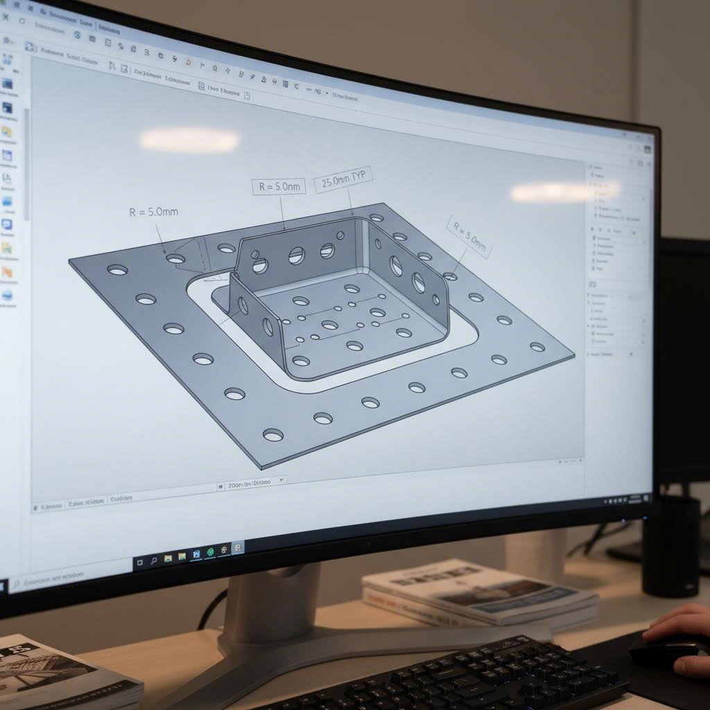
You've mastered material selection and thickness parameters—but here's a truth that catches many manufacturers off guard: even the most advanced laser metal cutter can't compensate for poor part design. The decisions you make at the CAD stage directly determine whether your laser cut metal parts come off the machine ready for assembly or require hours of costly post-processing.
Following proper design guidelines isn't just about avoiding errors. It's about achieving faster production, tighter tolerances, and lower per-part costs. When designs are optimized for laser cutting of metal sheets, parts fit together precisely, edges come out clean, and waste drops significantly. Let's walk through the specific, actionable guidelines that separate amateur designs from professional-grade laser cut sheet metal components.
Designing Corners and Curves for Clean Cuts
Sharp internal corners are the enemy of quality laser cutting metal operations. When a laser approaches a perfect 90-degree internal corner, it must stop, change direction, and restart—creating excessive heat buildup at that exact point. The result? Burn marks, material distortion, and stress concentrations that can cause cracking during subsequent bending operations.
The solution is straightforward: add corner radii. As a baseline, use internal corner radii of approximately 0.5× your material thickness. For a 2mm sheet, that means internal corners with at least a 1mm radius. This small adjustment allows the laser to maintain continuous motion through the curve, producing cleaner cuts and stronger parts.
For curves in general, verify your CAD program draws true arcs rather than segmented approximations. According to fabrication experts at Baillie Fab, longer flat segments in CAD drawings can get interpreted as facets instead of smooth curves during cutting—imagine wanting a circle but receiving a hexagon. Before submitting files, confirm all curved lines are drawn as continuous arcs.
Minimum Feature Sizes That Actually Work
Designing features smaller than your laser can reliably produce leads to melted-closed holes, burned-away slots, and rejected parts. Here are the minimums you need to respect:
- Hole diameter: Make hole diameters at least equal to your material thickness. For a 3mm sheet, design holes with a minimum 3mm diameter. Holes significantly smaller than the sheet thickness will distort or melt closed during cutting.
- Slot width: Keep slot widths at least 1.5× your laser's measured kerf width. Long, narrow slots are especially prone to distortion—if you need very narrow slots, consider switching to a punched feature or specialized cutting parameters.
- Web and bridge thickness: Internal webs connecting part sections should be at least 1× material thickness, preferably 1.5× for handling stability. Thinner bridges burn away or warp during cutting.
- Hole-to-edge distance: Allow at least 1× material thickness between any hole and the nearest edge. Aluminum and other reflective materials require 2× that distance or more to prevent edge distortion.
When it's absolutely necessary to place holes closer to edges than recommended, alternative processes like secondary drilling operations or waterjet cutting may be required—but expect increased costs and lead times.
Tab and Slot Design for Easy Assembly
Well-designed tabs and slots can eliminate the need for welding fixtures, reduce assembly time, and improve alignment accuracy. When creating laser cut metal sheets intended for assembly, follow these principles:
- Account for kerf: The laser removes material (typically 0.1–0.4mm), so mating parts need kerf compensation. Model mating edges with half the kerf subtracted from one part and half added to the other—or coordinate with your laser shop on fit tolerances.
- Design clearance: Slots should be slightly larger than tabs to allow for material variations and thermal expansion. A 0.1mm clearance per side works well for most applications.
- Include alignment features: Add small locating tabs or notches that guide parts into correct position before fastening.
- Use lead-ins strategically: Place small lead-ins on internal cutouts to prevent pierce marks on visible surfaces. Position them inside bend sections or on hidden faces.
Optimizing Part Nesting for Material Efficiency
Smart nesting—arranging parts on the sheet to maximize material usage—directly impacts your project costs. Every square inch of wasted material is money thrown away.
Consider these nesting strategies for laser cut aluminum, steel, and other sheet metals:
- Maintain consistent gaps: Allow 1–3mm spacing between parts depending on thickness to account for kerf and thermal spread.
- Avoid duplicate cut lines: Overlapping lines waste cutting time and create burrs.
- Use common-line cutting: When two parts share an edge, common-line cutting removes duplicate kerf and shortens cycle time—ideal for laser cut metal panels and straight-edged components.
- Remember border requirements: The laser cutter needs up to 0.5" (12.7mm) border around every part. Two 4'×4' parts won't fit on a 4'×8' sheet without accounting for this clearance.
- Orient parts to grain direction: Most metal sheets are 4'×10' with lengthwise grain. Orienting parts along the grain maximizes yield per sheet and can improve bending outcomes.
Common Design Mistakes to Avoid
Even experienced designers fall into these traps. Before submitting your files, check for these frequent errors:
- Features too close to edges: Parts with cutouts or holes near edges warp or tear during cutting and forming. Maintain minimum edge distances.
- Overly complex geometries: Intricate patterns with hundreds of tiny cuts dramatically increase cutting time—and cost. Simplify where possible without compromising function.
- Ignoring grain direction: For materials that will be bent, orienting the grain perpendicular to the bend line reduces cracking and unpredictable springback.
- Forgetting bend reliefs: When sheet metal bends, stress concentrates at corners. Without relief notches or cutouts, the material can tear or deform unpredictably.
- Placing holes too close to bend lines: Holes near bends distort when the sheet is formed, making them unusable for fasteners. Maintain at least 2× material thickness between holes and bend centerlines.
- Unconnected geometry: Open contours or unconnected lines in your CAD file result in poorly cut parts or require additional drafting time to fix.
DFM Principles That Reduce Costs
Design for Manufacturing (DFM) isn't just a buzzword—it's the systematic approach to designing parts that are easy and economical to produce. Applying DFM principles to your laser cutting projects delivers tangible benefits:
- Specify realistic tolerances: Tighter tolerances cost more. For sheet metal laser cutting, standard tolerances of ±0.1mm to ±0.3mm satisfy most applications without premium pricing.
- Standardize features: Using consistent hole sizes and slot dimensions across your design allows the laser to cut more efficiently without constant parameter changes.
- Design for material availability: Standard sheet sizes (4'×8', 4'×10') maximize nesting efficiency. Odd dimensions may require custom material orders with longer lead times.
- Consider downstream processes: If your laser cut parts will be bent, welded, or finished, design with those operations in mind from the start. Adding bend reliefs and weld access now saves rework later.
Good design is the foundation of successful sheet metal laser cutting projects. Every hour spent optimizing your design saves multiple hours in production and post-processing.
With your designs now optimized for laser cutting, how does this technology stack up against alternative cutting methods? Understanding when laser cutting excels—and when other approaches might serve you better—helps you make smarter manufacturing decisions.
Laser Cutting vs Alternative Metal Cutting Methods
Laser cutting dominates conversations about precision sheet metal fabrication—but is it always the right choice? The honest answer: no. Understanding when to use a metal cutting laser machine versus plasma, waterjet, or mechanical cutting helps you match the right technology to each project, avoiding overspending on precision you don't need or settling for quality that falls short.
Each cutting metal machine technology excels in specific scenarios. Choosing the wrong one can cost thousands in wasted material, excessive processing time, or parts that simply don't meet specifications. Let's break down exactly when laser cutting wins and when alternative methods deserve serious consideration.
| Feature | Laser Cutting | Plasma Cutting | Waterjet Cutting | Mechanical Shearing/Punching |
|---|---|---|---|---|
| Precision/Tolerance | ±0.1mm to ±0.3mm | ±0.5mm to ±1.5mm | ±0.1mm to ±0.25mm | ±0.1mm to ±0.5mm |
| Edge Quality | Excellent—clean, smooth edges with minimal burr | Moderate—may require secondary finishing | Excellent—smooth, no thermal effects | Good for straight cuts; may show shear marks |
| Heat-Affected Zone | Small (0.2–0.8mm depending on thickness) | Large (can exceed 3mm) | None—cold cutting process | None—mechanical process |
| Material Thickness Range | 0.5mm to 25mm (fiber); up to 50mm with high power | 3mm to 150mm+ | 0.5mm to 200mm+ | 0.5mm to 12mm typical |
| Operating Costs | Moderate—low consumables, electricity primary cost | Low—consumables inexpensive, fast cutting | High—abrasive material significant expense | Very low—minimal consumables |
| Best Applications | Thin-to-medium sheets, intricate designs, precision parts | Thick steel plates, structural fabrication, speed-critical work | Heat-sensitive materials, mixed materials, thick sections | High-volume simple shapes, blanking operations |
Laser vs Plasma for Production Speed and Precision
When should you reach for a plasma metal cutter instead of laser technology? The decision often comes down to material thickness and tolerance requirements.
Plasma cutting uses an electrical arc and compressed gas to melt and blast through conductive metals. It's fast, cost-effective, and handles thick materials that would challenge even high-powered industrial laser cutter systems. According to testing by Wurth Machinery, plasma cutting 1-inch steel runs about 3-4 times faster than waterjet, with operating costs roughly half as much per foot of cut.
However, plasma's advantages come with trade-offs:
- Precision gap: Plasma tolerances typically range from ±0.5mm to ±1.5mm—adequate for structural work but insufficient for precision components
- Edge quality: Cut edges often require grinding or finishing before welding or coating
- Heat-affected zones: The high-temperature process creates substantial HAZ that can alter material properties near the cut
- Limited complexity: Small holes and intricate patterns suffer from the wider kerf and less precise beam control
Laser cutting takes the opposite approach—trading raw thickness capacity for surgical precision. The metal cutting laser produces exceptionally clean edges with minimal post-processing, handles fine details effortlessly, and maintains tight tolerances throughout complex geometries.
Use plasma when:
- Working with thick conductive metals over 20mm
- Speed matters more than edge finish
- Parts will undergo secondary finishing anyway
- Budget constraints favor lower operating costs per inch
Use laser when:
- Tolerances tighter than ±0.5mm are required
- Parts need clean edges without secondary processing
- Designs include small holes, slots, or intricate patterns
- Working with thin-to-medium materials under 12mm
When Waterjet Cutting Beats Laser Technology
Waterjet cutting occupies a unique position in the metal cutter landscape. Using high-pressure water mixed with abrasive particles, it cuts through virtually any material without generating heat. This cold-cutting capability makes it indispensable for specific applications.
The waterjet market is expanding rapidly, projected to exceed $2.39 billion by 2034—and the growth reflects genuine advantages that laser technology simply cannot match:
- Zero heat-affected zone: No thermal distortion, no microstructural changes, no hardening at cut edges
- Material versatility: Cuts metals, stone, glass, composites, ceramics—anything except tempered glass and diamonds
- Thickness capacity: Handles materials up to 200mm+ with proper setup
- No toxic fumes: Eliminates hazards associated with cutting galvanized coatings or painted surfaces
However, waterjet comes with significant drawbacks. Operating costs run considerably higher than laser or plasma due to abrasive consumption. A complete waterjet system costs around $195,000 compared to approximately $90,000 for comparable plasma equipment. Cutting speeds are also slower—particularly on thinner materials where laser excels.
Choose waterjet when:
- Heat effects are absolutely unacceptable (aerospace components, heat-treated parts)
- Cutting mixed materials including non-metals
- Processing very thick sections where laser power becomes prohibitive
- Material properties must remain completely unchanged after cutting
Industry specialists at Xometry note that for stainless steel components, both fiber laser and waterjet deliver excellent precision and repeatability—while plasma typically requires secondary cleanup operations. The thicker the material, the more likely waterjet becomes the practical choice.
Mechanical Methods: The Overlooked Option
Sometimes the best metal cutting machine isn't a laser at all. Traditional die cut machine operations, shearing, and punching remain highly competitive for specific applications.
Mechanical cutting excels when:
- High volumes of simple shapes: Stamping and punching operations produce thousands of identical parts faster than any thermal process
- Straight-line cuts: Shearing creates clean, straight edges at speeds no laser can match for blanking operations
- Cost sensitivity: For basic shapes in high quantities, per-part costs drop dramatically compared to laser cutting
- No heat tolerance: Like waterjet, mechanical cutting introduces zero thermal effects
The limitations are equally clear. Complex geometries require expensive custom tooling. Design changes mean new dies. And precision varies with tool wear—making mechanical methods poorly suited for intricate parts or frequent design iterations.
Making the Right Technology Choice
No single cutting technology wins every scenario. The most successful fabrication shops often deploy multiple technologies, matching each project to its optimal process:
- Laser: Your go-to for precision sheet metal work, complex designs, and thin-to-medium materials
- Plasma: The workhorse for thick steel plate processing where speed and cost efficiency matter
- Waterjet: The specialist for heat-sensitive applications and materials that challenge thermal processes
- Mechanical: The volume champion for simple geometries at scale
There's no single "best" cutting technology—each has its place. For many fabrication shops, having access to at least two of these technologies provides the flexibility to handle almost any cutting task effectively and economically.
Understanding these trade-offs puts you in control of your manufacturing decisions. But even with the right technology selected, problems can still emerge during cutting operations. Let's tackle the most common issues and their solutions.
Troubleshooting Common Laser Cutting Problems
Even with perfect material selection and optimized design, things can still go wrong at the laser cutter metal stage. Burrs clinging to edges, dross accumulating on undersides, thin sheets warping under heat—these issues frustrate operators and delay production. The good news? Most problems trace back to identifiable causes with straightforward solutions.
Understanding why these defects occur transforms you from someone who reacts to problems into someone who prevents them. Whether you're running a laser metal cutter for production or prototyping, mastering these troubleshooting techniques saves material, time, and money.
Eliminating Burrs and Dross on Cut Edges
What exactly is dross? Define dross as the resolidified molten metal that adheres to the bottom edge of a cut—essentially slag that didn't get blown away during the cutting process. Burrs are similar unwanted material formations, typically appearing as raised edges or rough protrusions along cut lines. Both defects require secondary finishing operations that add cost and delay delivery.
Here's a problem-cause-solution breakdown for these edge quality issues:
-
Problem: Heavy dross accumulation on bottom edges
Cause: Cutting speed too fast, insufficient assist gas pressure, or nozzle positioned too far from material surface
Solution: Reduce cutting speed by 10-15%, increase gas pressure, and verify nozzle standoff distance is within manufacturer specifications (typically 0.5-1.5mm) -
Problem: Fine burrs along cut edges
Cause: Laser power too low for material thickness, worn nozzle, or contaminated optics reducing beam quality
Solution: Increase power settings, inspect and replace worn nozzles, clean or replace optical components -
Problem: Inconsistent dross—heavy in some areas, clean in others
Cause: Material thickness variation, uneven sheet surface, or fluctuating gas pressure
Solution: Verify material flatness, check gas supply consistency, and consider using material hold-down systems for warped sheets
When laser cutting ss (stainless steel), nitrogen assist gas is essential for clean, oxide-free edges. Oxygen cutting produces faster speeds but leaves an oxide layer that may be unacceptable for cosmetic or corrosion-sensitive applications. For stainless laser cutting applications requiring bright, clean edges, high-purity nitrogen (99.95%+) at adequate flow rates eliminates most dross issues.
Preventing Heat Distortion in Thin Materials
Thin sheet metals—particularly materials under 2mm—are prone to warping, bending, and buckling when excessive heat accumulates during cutting. The concentrated thermal energy that makes laser cutting so effective becomes a liability when it spreads beyond the immediate cut zone.
-
Problem: Overall sheet warping after cutting multiple parts
Cause: Heat buildup from cutting closely nested parts in sequence without cooling time
Solution: Implement skip-cutting patterns that distribute heat across the sheet; allow spacing between sequential cuts in the same area -
Problem: Localized distortion around cut features
Cause: Laser power too high for material thickness, cutting speed too slow
Solution: Reduce power while increasing speed—the goal is delivering just enough energy to cut through without excess heat input -
Problem: Parts curling or bending after being cut free from sheet
Cause: Residual stress release from heat-affected zones, particularly in parts with asymmetric geometries
Solution: Add stress-relief features to designs, use nitrogen assist gas to minimize HAZ, or switch to pulsed cutting modes for heat-sensitive work
Focus Position: The Hidden Quality Factor
Improper focus position causes more quality problems than many operators realize. When the laser beam isn't focused precisely at the optimal point relative to the material surface, cut quality degrades rapidly.
Focus affects cutting in several ways:
- Focus too high: Wider kerf, increased dross, rougher edges, and reduced cutting speed capability
- Focus too low: Incomplete cuts, excessive bottom-side melting, and potential damage to support slats
- Inconsistent focus: Variable edge quality across the sheet, particularly problematic on materials with surface irregularities
Modern fiber laser systems increasingly feature automatic focusing technology that continuously adjusts focal position based on material height sensing. This technology dramatically improves consistency—especially when processing materials with minor thickness variations or surface undulations. If your laser metal cutter offers auto-focus capabilities, use them. The improvement in cut consistency often justifies the feature's cost within months of operation.
Assist Gas Selection: More Than Just Blowing Air
The assist gas you choose fundamentally changes your cutting results. It's not simply about removing molten material—different gases interact chemically and thermally with the cut zone in distinct ways.
| Assist Gas | Best Applications | Edge Quality Impact | Key Considerations |
|---|---|---|---|
| Oxygen | Mild steel, carbon steel | Creates oxide layer; faster cutting | Exothermic reaction adds cutting energy; produces darker edges requiring cleaning for painting/welding |
| Nitrogen | Stainless steel, aluminum | Clean, oxide-free; bright finish | Higher gas consumption; slower speeds but superior cosmetic results |
| Compressed Air | Budget-conscious thin sheet work | Moderate; some oxidation | Lowest cost option; adequate for non-critical applications where edge finish is secondary |
Gas purity matters significantly. Impurities in oxygen or nitrogen cause inconsistent reactions, leading to variable edge quality. For critical stainless laser cutting applications, use nitrogen with purity of 99.95% or higher. Lower purity grades introduce oxygen contamination that defeats the purpose of nitrogen cutting.
Maintenance That Prevents Problems
Many cutting quality issues stem not from operator error but from deferred maintenance. Components wear, optics contaminate, and alignments drift over time. Proactive maintenance prevents problems before they affect production.
- Optical components: Inspect lenses and protective windows daily; contamination reduces beam quality and cutting power. Clean with appropriate solvents and replace when scratches or burns appear.
- Nozzles: Check nozzle condition regularly. Damaged or worn nozzles disrupt gas flow patterns, causing inconsistent cuts and increased dross. Replace at first sign of wear.
- Beam alignment: Misaligned beams produce off-center cuts with uneven edge quality. Follow manufacturer procedures for alignment verification—typically monthly for high-production environments.
- Cooling systems: Overheating degrades laser performance and can damage expensive components. Monitor coolant levels, check for blockages, and maintain chillers according to schedule.
- Gas delivery: Inspect hoses, regulators, and connections for leaks. Inconsistent gas pressure causes fluctuating cut quality that's difficult to diagnose without systematic checking.
Prevention beats correction every time. A 15-minute daily inspection routine catches issues before they become production-stopping problems.
With troubleshooting knowledge in hand, you're equipped to maintain consistent quality across your cutting operations. But quality requirements vary dramatically by industry—aerospace precision differs vastly from architectural panel work. Understanding these industry-specific demands helps you meet customer expectations and identify the right manufacturing partners for specialized projects.
Industry Applications and Quality Requirements
Where does all this precision cutting technology actually end up? The answer spans virtually every manufacturing sector you can imagine. From the chassis under your car to the decorative panels adorning modern buildings, laser-cut components surround us daily. Understanding how different industries leverage this technology—and the specific quality standards each demands—helps you navigate project requirements and identify capable manufacturing partners.
Each sector brings unique challenges. Aerospace tolerances that seem excessive for architectural work become essential when lives depend on component integrity. Knowing these distinctions ensures you specify the right requirements for your application without over-engineering (and overpaying) for capabilities you don't need.
Automotive and Aerospace Precision Requirements
The automotive and aerospace industries represent the most demanding applications for laser-cut sheet metal. Both require exceptional precision, but their specific needs differ significantly.
Automotive Applications
Modern vehicles contain hundreds of laser-cut components. The technology's speed and precision make it ideal for high-volume production where consistency matters as much as accuracy.
- Chassis components: Structural brackets, crossmembers, and reinforcement plates requiring tolerances of ±0.1mm to ±0.3mm
- Suspension parts: Control arm brackets, mounting plates, and spring seats demanding consistent geometry for proper vehicle dynamics
- Body panels and structural elements: Door intrusion beams, pillar reinforcements, and crash structure components where material integrity is safety-critical
- Heat shields and brackets: Engine bay components requiring complex geometries and tight nesting for material efficiency
- Custom metal signs and identification plates: VIN plates, warning labels, and branded components requiring fine detail reproduction
The automotive supply chain demands rigorous quality management. IATF 16949 certification—the internationally recognized standard for automotive quality management systems—has become essentially mandatory for suppliers serving OEMs and Tier 1 manufacturers. This certification, developed by the International Automotive Task Force, integrates with ISO 9001 while adding automotive-specific requirements for risk-based thinking, product traceability, and defect prevention.
When sourcing chassis, suspension, and structural components, automotive manufacturers benefit significantly from working with IATF 16949-certified suppliers like Shaoyi Metal Technology. Their rapid prototyping capabilities—with 5-day turnaround—combined with comprehensive DFM support exemplify what to look for in a manufacturing partner serving this demanding sector.
Aerospace Applications
Aerospace takes precision requirements even further. According to industry research from Accurl, the need for lightweight, high-strength materials in aerospace cannot be overstated—and laser cutting's high precision and ability to handle a wide range of materials makes it perfectly suited for this task.
- Precision panels: Fuselage skin sections, access panels, and fairings requiring tolerances as tight as ±0.05mm
- Lightweight structural components: Ribs, stringers, and bulkhead elements where every gram matters
- Engine components: Heat shields, mounting brackets, and ducting requiring exotic alloys and exceptional accuracy
- Interior fittings: Seat frames, overhead bin structures, and galley components balancing weight, strength, and fire resistance
Aerospace certification requirements go beyond standard quality management. AS9100 certification is typically mandatory, with additional traceability requirements ensuring every component can be tracked from raw material through final installation. Steel fabricators serving this sector must maintain meticulous documentation and demonstrate consistent process control across extended production runs.
Electronics and General Manufacturing
The electronics industry relies heavily on laser cutting for components requiring miniaturization and precision. As devices shrink while becoming more powerful, the technology that creates their housings must keep pace.
- Enclosures and chassis: Server racks, control cabinets, and equipment housings requiring precise cutouts for connectors, displays, and ventilation
- Heat sinks: Intricate fin patterns maximizing surface area within tight spatial constraints
- EMI/RFI shielding: Precision shields with complex aperture patterns for cable routing while maintaining electromagnetic integrity
- Mounting brackets: Circuit board supports, drive cages, and component mounts requiring consistent hole placement for automated assembly
General manufacturing spans countless applications where metal fab capabilities meet diverse needs. From agricultural equipment components to food processing machinery, laser cutting enables efficient production across industries where precision and repeatability drive success.
Decorative and Architectural Metal Applications
Architecture and decorative metalwork showcase laser cutting's artistic potential alongside its technical capabilities. Here, aesthetic considerations often rival dimensional accuracy in importance.
- Laser cut decorative metal panels: Intricate patterns for privacy screens, room dividers, and facade elements transforming buildings into visual statements
- Laser cut steel panels: Exterior cladding, sculptural installations, and landscape features combining durability with design freedom
- Signage and wayfinding: Dimensional letters, illuminated signs, and directional systems requiring clean edges and precise geometry
- Custom architectural elements: Stair railings, balustrades, and ornamental grilles blending structural function with decorative intent
- Interior design features: Reception desk panels, ceiling elements, and wall art where laser cutting enables designs previously impossible or prohibitively expensive
When searching for metal fabricators near me for architectural projects, look for shops with portfolio examples demonstrating both technical capability and design sensitivity. The best steel fabrication partners for decorative work understand that visible surfaces demand flawless edges and consistent finishes—not just dimensional accuracy.
Tolerance Requirements by Application
Understanding industry-specific tolerance expectations helps you specify requirements appropriately:
| Industry Sector | Typical Tolerance Range | Key Quality Drivers |
|---|---|---|
| Aerospace | ±0.05mm to ±0.1mm | Safety certification, material traceability, fatigue life |
| Automotive (safety-critical) | ±0.1mm to ±0.2mm | IATF 16949 compliance, crashworthiness, assembly fit |
| Automotive (general) | ±0.2mm to ±0.3mm | Interchangeability, production consistency |
| Electronics | ±0.1mm to ±0.25mm | Component fit, thermal management, EMI performance |
| Architectural/Decorative | ±0.3mm to ±0.5mm | Visual appearance, installation alignment |
| General Manufacturing | ±0.2mm to ±0.5mm | Functional fit, cost optimization |
The right tolerance specification balances functional requirements against cost. Over-specifying precision for non-critical applications wastes money; under-specifying for safety-critical components risks failure.
Industry applications demonstrate laser cutting's remarkable versatility—but versatility comes with cost considerations. Understanding what drives project pricing helps you optimize spending while meeting quality requirements.
Cost Factors and Project Pricing Optimization
How much does sheet metal laser cutting actually cost? It's a question every manufacturer asks—yet the answer frustrates many because it depends on so many variables. Unlike commodities with fixed pricing, laser cutting costs fluctuate based on design choices, material selection, quantities, and finishing requirements. Understanding these cost drivers puts you in control, enabling smarter decisions that reduce expenses without sacrificing quality.
Whether you're evaluating quotes from fabricators or considering how much is a laser cutting machine for in-house operations, grasping the economics behind each factor helps you optimize spending across every project phase.
Understanding Per-Part Cost Drivers
Every laser cutting quote reflects a combination of factors that multiply together to determine your final price. Here's what actually drives costs:
Material Costs
Raw material represents the most straightforward cost component—but thickness and alloy selection significantly impact pricing. According to fabrication specialists at Komacut, different materials have unique properties that affect cutting speed, energy consumption, and equipment wear. Cutting stainless steel generally requires more energy and time compared to cutting carbon steel, making it more expensive. Soft or thin materials, on the other hand, are typically faster and cheaper to cut.
- Material grade: Premium alloys like 316 stainless cost more than standard 304 or mild steel
- Thickness: Thicker materials require more energy, slower speeds, and increased cutting time
- Sheet size efficiency: Standard 4'×8' sheets maximize nesting; odd sizes may require custom orders with premiums
Cutting Time and Complexity
Time is money in laser cutting—literally. Every second the laser cutting machine for metal runs adds to your cost. Two primary factors determine cutting time:
- Total cut length: Longer perimeters and more cutouts mean extended machine time
- Number of pierce points: Each internal feature requires the laser to pierce through the material, adding time with every cutout. As industry experts note, more pierce points and longer cutting paths increase the cutting time and energy required, raising overall costs
- Geometric complexity: Intricate designs with tight curves require slower speeds for quality edges
Setup and Programming Fees
Before cutting begins, your job requires programming and machine setup. These fixed costs get amortized across your order quantity—making per-part costs dramatically different between 10-piece and 1,000-piece orders.
Post-Processing Requirements
Secondary operations add labor, equipment time, and material costs. Common post-processing includes:
- Deburring: Removing edge burrs for safe handling and assembly
- Bending and forming: Converting flat cuts into three-dimensional parts
- Surface finishing: Polishing, grinding, painting, or powder coating
- Hardware insertion: Adding fasteners, studs, or threaded inserts
According to manufacturing cost analysis, secondary processes such as chamfering and threading add to overall cost by requiring additional labor, specialized equipment, and extended production time.
Strategies for Reducing Laser Cutting Expenses
Smart manufacturers don't just accept quoted prices—they optimize designs and ordering strategies to minimize costs. Here are the most effective approaches, ranked by typical impact:
- Simplify your design geometry: Complex shapes with intricate details require more precise laser control and longer cutting times. Industry research from Vytek confirms that avoiding sharp interior corners, minimizing small intricate cuts, and using fewer curves can result in substantial savings. Rounded corners or straight lines are generally faster to cut than intricate shapes or tight radii.
- Optimize material nesting: Efficient nesting maximizes material usage by arranging parts closely together, minimizing waste. Strategic nesting can reduce material scrap by 10-20% according to fabrication experts. Work with your supplier to ensure parts are arranged for maximum sheet utilization.
- Consolidate orders for batch processing: Laser cutting machine price efficiency improves dramatically with volume. Setting up a laser cutter takes time, so running larger quantities in one session reduces frequent machine adjustments and lowers per-part setup costs. Bulk orders often qualify for material discounts from suppliers as well.
- Match edge quality to actual requirements: Not every application demands premium edge finish. As Vytek notes, achieving high-quality edges often requires slowing down the laser or using more power—both increasing costs. For parts that will be assembled into larger components or undergo further finishing, standard edge quality may be perfectly adequate.
- Select appropriate materials and thicknesses: If your application doesn't demand thicker or harder metals, opting for thinner material saves both cutting time and raw material costs. Certain materials like aluminum and thinner sheet metals cut faster and require less laser power, translating to reduced operating expenses.
- Specify realistic tolerances: Tighter tolerances require slower cutting speeds and more rigorous quality control. Standard tolerances of ±0.2mm to ±0.3mm satisfy most applications without premium pricing.
Prototyping Economics vs Production Runs
The economics of laser cutting shift dramatically between prototype quantities and production volumes. Understanding these dynamics helps you budget appropriately and identify the right manufacturing partners for each phase.
Prototype Phase Considerations
During prototyping, speed often matters more than per-part cost. You need parts fast to validate designs, test fits, and iterate quickly. The premium for small quantities reflects setup costs spread across few parts—but the alternative (delayed development timelines) typically costs far more in the long run.
Suppliers like Shaoyi Metal Technology address this challenge with 12-hour quote turnaround and 5-day rapid prototyping capabilities, enabling faster design iteration and cost validation before committing to production tooling. This accelerated timeline helps manufacturers identify design issues early when changes cost least.
Production Volume Break-Even
As quantities increase, per-part costs drop substantially. The break-even point—where investing in production optimization becomes worthwhile—typically occurs between 50 and 500 parts depending on complexity. Consider these factors:
- Setup amortization: Fixed programming and setup costs become negligible per-part at higher volumes
- Material efficiency: Larger orders allow optimized nesting across multiple sheets
- Process optimization: Production quantities justify investing in cutting parameter refinement
- Supplier pricing tiers: Most fabricators offer volume discounts starting at 100+ pieces
Scaling from Prototype to Volume
The transition from prototype to production creates opportunities for cost reduction—but requires manufacturing partners with capabilities across both phases. Suppliers with automated mass production capabilities alongside rapid prototyping services enable seamless scaling without changing vendors mid-project. This continuity preserves institutional knowledge about your parts and eliminates re-learning curves that add cost and risk.
The cheapest prototype isn't always the best value. Speed to validation and design feedback often outweigh per-part savings during development phases.
Whether you're cutting a single prototype or scaling to thousands of production parts, understanding these cost dynamics helps you make informed decisions. But cost optimization means nothing if safety protocols fail. Proper operational practices protect both your team and your investment in metal cutting machines—making safety knowledge essential for anyone involved in laser cutting operations.
Safety Protocols and Operational Best Practices
Cost optimization and precision cutting mean nothing if someone gets hurt. Metal laser cutting involves concentrated energy, molten material, hazardous fumes, and fire risks—all requiring systematic safety measures. Whether you operate a laser cutter for metal in-house or partner with fabrication shops, understanding these protocols protects people, equipment, and your bottom line.
The laser cutting sheet metal process introduces hazards that differ significantly from traditional machining. Intense light beams, vaporized metals, and high temperatures demand respect and preparation. Let's walk through the essential safety framework every operation needs.
Essential Safety Equipment and Protocols
Laser safety starts with understanding classifications. Most industrial metal sheet cutting systems fall into Class 4—the highest hazard category—meaning direct or scattered beam exposure can cause immediate eye and skin injury. This classification drives PPE requirements and operational protocols.
Before any cutter machine metal operation begins, verify these safety essentials are in place:
- Laser safety eyewear: Specifically rated for your laser's wavelength (1.06 μm for fiber, 10.6 μm for CO2). Generic safety glasses provide zero protection against laser radiation.
- Protective clothing: Long sleeves and pants made from non-flammable materials. Avoid synthetic fabrics that melt when exposed to sparks.
- Enclosed beam path: Modern systems should fully enclose the cutting area with interlocked doors that shut down the laser when opened.
- Warning signage: Clearly posted laser hazard signs at all entry points to the cutting area.
- Training documentation: According to safety guidance from Boss Laser, all individuals operating or working near laser cutting equipment should receive comprehensive training on safety protocols, including potential hazards associated with laser radiation and safe operation procedures.
- Designated Laser Safety Officer: Someone with knowledge and expertise to oversee safe equipment use, conduct hazard assessments, and ensure compliance with regulatory standards.
Ventilation Requirements for Metal Fume Control
When lasers vaporize metal, they don't just create clean cuts—they generate fumes containing potentially hazardous particles and gases. Proper ventilation isn't optional; it's a regulatory requirement and a health necessity.
According to OSHA regulations, employers must provide ventilation systems that keep hazardous chemicals below exposure limits. These include general and local exhaust ventilation systems—general systems use natural or forced fresh air while local exhaust systems use movable hoods to remove fumes at the source.
Different materials create different hazards:
- Galvanized steel: The zinc coating vaporizes at lower temperatures than steel, releasing fumes that can cause metal fume fever—symptoms include fever, nausea, and coughing. OSHA requires employers to provide general or local exhaust ventilation when working with zinc-bearing materials.
- Stainless steel: Releases chromium during cutting. OSHA mandates that no employee be exposed to airborne chromium concentrations exceeding 5 micrograms per cubic meter of air as an 8-hour time-weighted average. Chromium is highly toxic and can damage eyes, skin, nose, throat, and lungs.
- Painted or coated materials: Unknown coatings may release toxic compounds. Always identify coatings before cutting and implement appropriate extraction.
- Oily surfaces: Oil residue creates additional smoke and potential fire hazards. Clean materials before cutting when possible.
Never cut galvanized, coated, or contaminated metals without verified ventilation. Short-term exposure causes immediate symptoms; long-term effects include lung damage and cancer risk.
Fire Prevention and Emergency Response
Laser cutting creates sparks, molten metal, and intense localized heat—a combination that demands serious fire prevention measures. The metal sheet material itself won't burn, but accumulated debris, assist gas residue, and nearby materials can ignite.
- Keep work areas clean: Remove scrap, debris, and combustible materials from the cutting zone before operations begin.
- Fire suppression systems: Automatic suppression systems inside enclosed cutting areas provide critical protection. Portable extinguishers should be immediately accessible.
- Material inspection: Check sheets for oil contamination, protective films, or coatings that could ignite or produce toxic fumes.
- Never leave operating equipment unattended: Even with modern safety features, human monitoring catches problems automated systems may miss.
- Emergency shutdown procedures: All operators must know how to immediately stop the laser and shut down the system. Post procedures visibly near equipment.
- Standard Operating Procedures: Develop SOPs covering machine startup, shutdown, material handling, and emergency response. Review and update these procedures regularly.
Choosing the Right Approach for Your Projects
Throughout this guide, you've explored the technology, materials, parameters, and applications that define successful laser cutting sheet metal operations. The final consideration? Matching all these elements to your specific needs.
Selecting the right laser cutting approach means evaluating:
- Technology fit: Fiber lasers for reflective metals and high-speed thin sheet work; CO2 for mixed-material versatility and thick steel sections
- Material requirements: Matching laser wavelength to material absorption characteristics for optimal efficiency
- Quality specifications: Aligning tolerance requirements with industry standards—aerospace precision differs from architectural applications
- Manufacturing partners: Certifications like IATF 16949 for automotive, AS9100 for aerospace, and demonstrated capabilities in your specific material and thickness ranges
- Safety infrastructure: Verified ventilation, PPE programs, and trained personnel—whether in-house or at your supplier's facility
The most successful projects start with this comprehensive understanding. You now know when fiber beats CO2, which materials demand special attention, how thickness affects parameters, and what design choices optimize outcomes. Combined with proper safety protocols, this knowledge transforms laser cutting from a mysterious technology into a tool you can specify, optimize, and trust.
Whether you're cutting your first prototype or scaling to production volumes, the fundamentals remain constant: match the technology to your materials, design for the process, maintain rigorous safety standards, and partner with manufacturers who share your commitment to quality. That's how precision sheet metal fabrication delivers results worth building on.
Frequently Asked Questions About Laser Cutting Sheet Metal
1. Can a laser cutter cut sheet metal?
Yes, modern laser cutters handle a wide variety of metals with exceptional precision. Fiber lasers cut steel, aluminum, copper, brass, and titanium with tolerances as tight as ±0.1mm. CO2 lasers work well for mild steel and mixed-material applications. Industrial systems can process materials from 0.5mm to over 25mm thickness depending on laser power, making laser cutting a preferred method for automotive, aerospace, electronics, and architectural fabrication.
2. How much does it cost to get metal laser cut?
Laser cutting costs depend on material type, thickness, design complexity, and quantity. Cutting time drives most expenses—complex geometries with many pierce points cost more than simple shapes. Setup fees get amortized across order quantities, making larger batches more economical per part. Material costs vary significantly between mild steel and premium alloys like 316 stainless. Working with certified suppliers like Shaoyi Metal Technology, which offers 12-hour quote turnaround, helps you get accurate pricing quickly for cost validation.
3. What materials should not be laser cut?
Avoid laser cutting materials containing PVC, PTFE (Teflon), polycarbonate with bisphenol A, and chromium-containing leather—these release toxic fumes. Beryllium oxide is extremely hazardous. Reflective metals like copper and brass require high-power fiber lasers; CO2 lasers cannot cut them effectively. Always ensure proper ventilation when cutting galvanized steel due to toxic zinc fumes, and never cut unknown coatings without identifying their composition first.
4. What is the difference between fiber and CO2 lasers for metal cutting?
Fiber lasers operate at 1.06 micron wavelength, cutting reflective metals like aluminum and copper 2-3x faster than CO2 while using one-third the operating power. They require minimal maintenance with no mirror alignment or gas refills. CO2 lasers at 10.6 microns excel at cutting thick mild steel with smooth edges and offer versatility for non-metal materials like plastics and wood. Choose fiber for high-volume thin sheet work; CO2 for mixed-material shops or very thick steel sections.
5. How do I optimize my design for laser cutting costs?
Simplify geometries by avoiding intricate details and tight interior corners—rounded corners cut faster than sharp angles. Maximize material nesting to reduce waste by 10-20%. Consolidate orders for batch processing to spread setup costs. Specify realistic tolerances (±0.2mm to ±0.3mm satisfies most applications). Choose appropriate material thicknesses since thinner sheets cut faster. Partners with rapid prototyping capabilities like Shaoyi Metal Technology enable quick design validation before committing to production volumes.