 Small batches, high standards. Our rapid prototyping service makes validation faster and easier —

Laser Sheet Metal Cutting Decoded: From Fiber Lasers To Flawless Edges
What Is Laser Sheet Metal Cutting and Why It Dominates Modern Fabrication
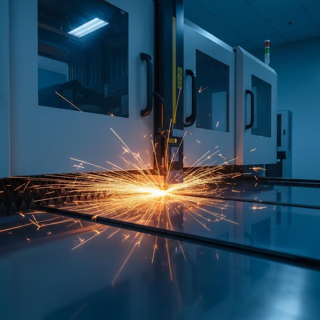
Imagine cutting through a metal sheet with the precision of a surgeon's scalpel, leaving edges so clean they require no additional finishing. That's exactly what laser sheet metal cutting delivers. This process uses a high-power laser beam, directed through sophisticated optics and computer numerical control (CNC), to melt, burn, or vaporize material along a programmed path. The result? Intricate shapes cut from steel, aluminum, and other metals with tolerances that mechanical methods simply cannot match.
At its core, this technology represents the intersection of physics and precision engineering. A focused laser beam—typically under 0.0125 inches (0.32 mm) in diameter at its narrowest point—delivers concentrated energy exactly where it's needed. Unlike punching or shearing, which rely on physical force, metal laser cutting uses thermal energy to cleanly separate material without mechanical contact or tool wear.
The Science Behind Focused Light Cutting
How does a beam of light cut through solid steel? The answer lies in energy concentration. A laser cutter generates its beam by stimulating lasing materials—whether gas, crystal, or fiber—through electrical discharges or lamps within a closed container. This energy is amplified by internal reflection until it escapes as a coherent stream of monochromatic light.
Here's where things get fascinating. Mirrors or fiber optics direct this beam through a lens that intensifies it to an incredibly small focal point. When this concentrated energy contacts the metal sheet, it rapidly heats the material past its melting or vaporization point. A jet of assist gas—typically oxygen, nitrogen, or compressed air—then blows away the molten material, leaving a precise cut with a high-quality surface finish.
The process follows a motion control system that executes CNC or G-code instructions, allowing the laser head to trace complex patterns across the workpiece with remarkable accuracy. Need to start cutting in the middle of a sheet rather than the edge? A piercing process uses high-power pulses to burn through the material first—taking roughly 5-15 seconds to pierce a 0.5-inch-thick stainless steel sheet.
From Industrial Origins to Precision Manufacturing
The journey from laboratory curiosity to metal fabrication cornerstone spans over six decades. Albert Einstein laid the theoretical groundwork in 1917 with his concept of "stimulated emission of radiation." However, it wasn't until 1960 that Theodore Maiman built the first working laser in a California laboratory—a ruby laser that many contemporaries dismissed as "a solution looking for a problem."
The skeptics were wrong. By 1964, Kumar Patel at Bell Labs had developed the carbon dioxide gas laser, creating a faster and more cost-effective cutting method. The following year, the Western Engineering Research Center in Buffalo became the first group to use focused laser beam cutting industrially, drilling holes in diamond dies for wire manufacturing.
The real breakthrough came in 1969 when Boeing became the first company to use gas laser cutting commercially, applying it to titanium and other aerospace materials. Throughout the 1980s, adoption exploded—an estimated 20,000 industrial laser cutters were operating worldwide, collectively valued at approximately $7.5 billion.
Today, sheet metal fabrication relies heavily on this technology for everything from automotive chassis components to architectural panels. Modern CNC-controlled systems can execute designs directly from CAD files, enabling rapid prototyping and high-volume production with equal ease. What distinguishes laser cutting from mechanical alternatives isn't just precision—it's the ability to produce complex geometries, tight tolerances, and clean edges in a single operation, fundamentally transforming how we approach metal fabrication.
Fiber vs CO2 vs Nd YAG Lasers Explained
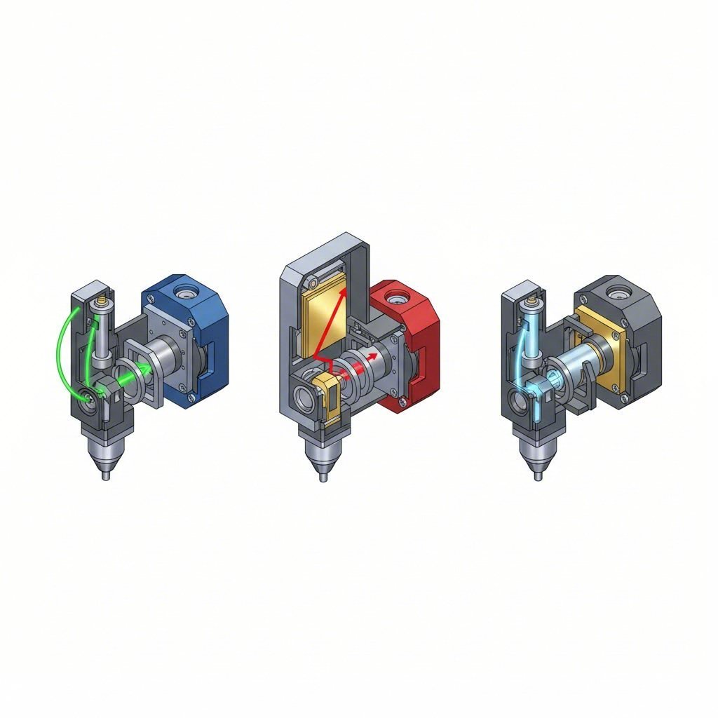
So you've decided laser cutting is right for your project. Now comes the question that trips up even experienced fabricators: which laser type should you choose? The three dominant technologies—fiber, CO2, and Nd:YAG lasers—each bring distinct strengths to the table. Understanding their differences isn't just academic; it directly impacts your cutting speed, operating costs, and the quality of your finished parts.
Think of it this way: choosing a laser type is like selecting the right tool for a job. You wouldn't use a sledgehammer to hang a picture frame. Similarly, a metal laser cutting machine optimized for thin stainless steel performs very differently than one designed for thick carbon steel or mixed-material applications.
| Specification | Fiber Laser | CO2 Laser | Nd:YAG Laser |
|---|---|---|---|
| Wavelength | ~1.06 µm | ~10.6 µm | ~1.064 µm |
| Photoelectric Efficiency | >25-30% | 10-15% | ~3% |
| Material Compatibility | All metals (excellent for reflective metals) | Metals and non-metals (wood, acrylic, textiles) | Specialty metals, titanium, high-strength alloys |
| Cutting Speed (thin metal) | 1.3-2.5x faster than CO2 | Baseline | Slower than both |
| Max Steel Thickness | Up to 50mm+ (high power) | Up to 25mm | Limited to thin materials |
| Operating Costs | Low (minimal maintenance) | Higher (gas, optics maintenance) | Moderate (crystal/cooling maintenance) |
| Energy Consumption | 30-50% of CO2 at same power | Higher (4-6kW for 1kW output) | Between fiber and CO2 |
| Ideal Applications | Industrial metal cutting, automotive, precision parts | Mixed-material shops, signage, non-metal cutting | Medical devices, aerospace, micro-fabrication |
Fiber Lasers and the Speed Revolution
Here's a number that gets fabricators' attention: fiber laser cutting runs 1.3 to 2.5 times faster than CO2 when processing sheets 5mm or thinner. For stainless steel specifically, that speed advantage can double. When you're running production batches, this translates directly to more parts per hour and lower cost per piece.
But speed isn't the only story. A fiber laser cutter delivers exceptional efficiency because of its shorter wavelength (approximately 1 µm), which metals absorb more readily than CO2's longer 10.6 µm wavelength. This means more of your input energy actually goes into cutting rather than being reflected away—particularly crucial when working with copper, brass, aluminum, and other reflective materials that traditionally challenged older laser systems.
The efficiency gains compound when you look at operating costs. Fiber laser cutters consume roughly 30-50% of the electricity that a comparable CO2 system requires. They also eliminate the mirrors and lenses that need regular cleaning or replacement, dramatically reducing maintenance downtime and consumable expenses.
What about thicker materials? This is where understanding power selection becomes essential. Here's a practical guide for matching laser power to your material needs:
- 500W-1.5kW: Thin sheets up to 3mm—ideal for decorative panels, brackets, and light-gauge components
- 3kW-6kW: The industrial sweet spot covering most fabrication needs, handling medium thicknesses with excellent speed
- 10kW-40kW: Heavy plate cutting where speed on thick material justifies the investment
One consideration: while fibre laser cutter technology excels at thin-to-medium plates, cut surface quality on very thick materials (beyond 20mm) can show visible striping. For applications requiring pristine edge finish on heavy plate, this tradeoff deserves attention during equipment selection.
When CO2 Still Makes Sense
Despite fiber's dominance in metal processing, dismissing CO2 lasers entirely would be shortsighted. Their longer wavelength—which limits metal cutting efficiency—becomes an advantage when working with organic materials. Wood, acrylic, leather, textiles, and plastics absorb this wavelength exceptionally well.
If your shop handles mixed materials—cutting steel one hour and acrylic signage the next—CO2 laser cutting steel and non-metals on the same machine offers genuine versatility. This matters particularly for job shops serving diverse industries or manufacturers producing products that combine metal with other materials.
CO2 systems also carry lower laser hazard classifications than fiber lasers, simplifying safety requirements. And for co2 laser metal cutting in the 6-25mm thickness range, well-maintained CO2 equipment delivers respectable performance with smooth cut edges—though expect slower speeds compared to modern fiber alternatives.
The market reality tells the story: fiber lasers now dominate new installations for dedicated laser metal cutting applications. CO2 retains its niche in mixed-material environments and shops with existing equipment that still performs adequately. For pure metal fabrication, however, the fiber laser cutter has become the default choice for good reason.
Nd:YAG lasers occupy a specialized corner of the market. Their high precision suits medical device manufacturing, aerospace components, and applications requiring cuts in titanium or exotic alloys. However, their lower photoelectric efficiency (around 3%) and limited thickness capacity make them impractical for general sheet metal work.
Understanding these distinctions positions you to make smarter equipment decisions—but laser type is only part of the equation. The materials you're cutting and their thickness play an equally critical role in determining what's actually achievable with any given system.
Material Compatibility and Thickness Capabilities
Ever wondered why your fabricator quotes different lead times for aluminum versus steel—even when the parts look identical? The answer lies in how different metals interact with laser energy. Material properties like reflectivity, thermal conductivity, and melting point dramatically influence what's achievable with any given laser system. Getting this wrong means rejected parts, blown budgets, or worse—damage to expensive equipment.
Let's break down exactly what you can cut, how thick you can go, and which metals require special handling.
Thickness Limits by Metal Type
The table below provides practical guidelines for maximum cutting thicknesses across common metals at different power levels. These figures assume fiber laser systems with optimized parameters—your specific results may vary based on equipment condition, assist gas selection, and desired edge quality.
| Material | 1kW | 2kW | 6kW | 10kW+ | Key Considerations |
|---|---|---|---|---|---|
| Mild Steel | 6mm | 10mm | 20mm | 50mm+ | Oxygen assist enables faster cuts; nitrogen for oxide-free edges |
| Stainless Steel Sheet | 4mm | 8mm | 16mm | 40mm+ | Nitrogen assist recommended for clean, oxide-free finishes |
| Aluminum Sheet | 3mm | 6mm | 15mm | 25mm | High reflectivity requires fiber lasers; nitrogen assist essential |
| Brass | 2mm | 4mm | 10mm | 15mm | Reflective; lower speeds and higher power needed |
| Copper | 1mm | 3mm | 8mm | 12mm | Most challenging due to extreme reflectivity and conductivity |
Notice the pattern? Reflective metals like aluminum, brass, and copper consistently show lower maximum thicknesses compared to steel at equivalent power levels. This isn't a limitation of modern equipment—it's physics at work.
Matching Laser Power to Your Material Needs
Why do some metals cut easily while others fight back? Two material properties explain most of what you'll encounter:
- Reflectivity: Highly reflective surfaces bounce laser energy away from the cut zone. Aluminum reflects approximately 90% of CO2 laser wavelengths, which is why fiber lasers with their shorter wavelengths have become the preferred choice for aluminum sheet metal.
- Thermal Conductivity: Materials like copper and aluminum dissipate heat rapidly throughout the sheet. This means more energy gets absorbed by surrounding material rather than concentrated at the cut point—requiring higher power and slower speeds to maintain penetration.
For stainless steel sheet metal applications, the balance is more forgiving. Stainless steel absorbs laser energy efficiently and conducts heat moderately, making it one of the most predictable materials to cut. A 2kW system handles most general fabrication needs up to 8mm, while 6kW opens the door to medium-plate structural work.
Here's a practical framework for power selection:
- Thin gauge work (under 3mm): 1-2kW systems deliver excellent speed and edge quality across most metals
- Medium fabrication (3-10mm): 3-6kW provides the versatility most job shops need
- Heavy plate cutting (10mm+): 10kW and above becomes essential for production efficiency
Can You Laser Cut Aluminum?
Absolutely—but it requires understanding what makes this metal different. The question "can you laser cut aluminum" comes up frequently because aluminum's high reflectivity historically caused problems, including back-reflections that could damage laser optics.
Modern fiber lasers have largely solved this challenge. Their shorter wavelength (around 1 µm) is absorbed more readily by aluminum than CO2's 10.6 µm wavelength. Combined with advanced back-reflection protection in newer systems, laser cutting aluminum has become routine for experienced fabricators.
That said, aluminium laser cutting demands specific considerations:
- Assist gas selection: Nitrogen produces clean, oxide-free edges essential for visible surfaces or subsequent welding
- Power adjustment: Expect to use 20-30% more power compared to steel of equivalent thickness
- Speed calibration: Cutting speeds for thin aluminum (up to 3mm) typically range from 1,000-3,000 mm/min, while heavier gauges (6mm+) may require 200-800 mm/min
- Surface preparation: Clean material free of oils and oxidation improves consistency
For reference, a 10mm thickness of aluminum sheet can be cut with good results using fiber lasers rated between 3-6kW. Lower power systems may struggle with throughput or edge quality at this thickness.
Common aluminum grades suited for laser cut aluminum applications include 5052, 5083, and 6061. These alloys offer good weldability and cut cleanly. Grade 7075, while popular for structural applications, requires higher power and slower speeds due to its hardness—producing rougher edges that may need secondary finishing.
The bottom line? Laser cutting aluminum is not only possible but increasingly cost-effective. The key lies in matching your equipment capabilities to material requirements and working with operators who understand the specific parameters these reflective metals demand.
With material compatibility established, the next critical question becomes precision: what tolerances can you actually achieve, and how do factors like kerf width and edge quality affect your designs?
Precision Tolerances and Edge Quality Standards
You've selected your laser type and confirmed your material will cut cleanly. Now comes the question that separates acceptable parts from exceptional ones: how precise can laser cutting actually be? Whether you're producing aerospace brackets where every tenth of a millimeter matters or decorative panels where visual consistency trumps dimensional exactness, understanding tolerance capabilities shapes realistic expectations and smarter design decisions.
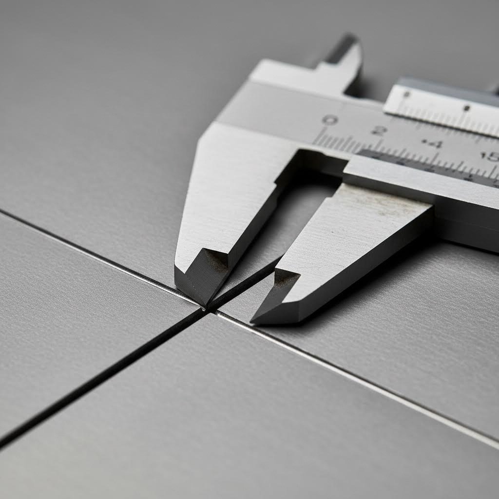
Here's the encouraging news: laser cutting sheet metal ranks among the most accurate thermal cutting processes available. High-end industrial systems routinely achieve tolerances of ±0.1mm under optimal conditions, with fiber lasers pushing even tighter—down to ±0.05mm or ±0.025mm for precision sheet metal work. For context, that's roughly the thickness of a human hair separating your cut dimension from the design specification.
But those headline figures come with important caveats. Material thickness, part geometry, and equipment condition all influence what's actually achievable on your specific project.
Understanding Kerf and Its Design Implications
Before diving into tolerance numbers, you need to understand kerf—the width of material removed by the laser beam during cutting. Think of it as the laser's "bite." Every cut consumes a small amount of material, typically ranging from 0.1mm to 1.0mm depending on material type, thickness, and cutting parameters.
Why does this matter for your designs? Consider a simple example: you're cutting a 100mm square from sheet steel. If your kerf width is 0.3mm and the cutting path follows the outside of your design line, your finished part measures 100mm. But if the path centers on the line, you lose 0.15mm from each edge—delivering a 99.7mm part instead.
Professional laser metal sheet cutting operations compensate for kerf automatically through software offsets. However, designers should understand these implications:
- Mating parts: When cutting interlocking components, kerf allowance determines fit. Ignore it, and your tabs won't seat into slots properly.
- Nested designs: Parts cut adjacent to each other share kerf losses. Factor this into critical dimensions.
- Thin features: Minimum feature widths must exceed kerf width—otherwise you're cutting through the feature entirely.
As a practical guideline, most fabricators recommend minimum feature sizes of at least 1.5 to 2 times the material thickness. For a 2mm steel sheet with typical kerf around 0.2-0.3mm, that means designing features no smaller than 3-4mm wide.
Precision Standards for Critical Applications
Tolerance requirements vary dramatically across industries. Automotive and aerospace components demand the tightest control, where even minor deviations cascade into assembly problems or safety concerns. Decorative architectural panels, by contrast, prioritize visual consistency over dimensional exactness.
Here's what to expect from laser cutting sheet metal across different precision tiers:
| Tolerance Level | Typical Range | Common Applications | Equipment Requirements |
|---|---|---|---|
| Standard Industrial | ±0.25mm | General fabrication, brackets, enclosures | Well-maintained production equipment |
| High Precision | ±0.1mm | Automotive components, medical devices | Premium fiber lasers, controlled environment |
| Ultra-Precision | ±0.025mm to ±0.05mm | Aerospace, electronics, micro-fabrication | Linear motor drives, climate-controlled facilities |
Material thickness significantly impacts achievable precision. As thickness increases, maintaining tight tolerances becomes exponentially more challenging. A 2mm stainless steel sheet might hold ±0.1mm easily, while the same equipment cutting 15mm plate may only guarantee ±0.25mm to ±0.5mm due to beam divergence, heat accumulation, and dross removal challenges.
Edge Quality: What Affects Your Final Finish
Tolerance numbers only tell part of the story. Edge quality—the smoothness, verticality, and cleanliness of cut surfaces—often matters equally for functional parts. Several interconnected factors determine whether your laser cut metal emerges with mirror-smooth edges or requires secondary finishing.
- Laser power: Insufficient power produces incomplete cuts and rough edges; excessive power causes over-melting and ablation.
- Cutting speed: Too fast prevents complete penetration; too slow increases heat input, widening the heat-affected zone and degrading edge quality.
- Assist gas type: Oxygen enables faster cuts on carbon steel but leaves oxidized edges. Nitrogen produces clean, oxide-free surfaces ready for welding or coating.
- Focal point position: Placing the focus correctly relative to material surface controls kerf geometry and edge verticality. Thick materials often require negative focus (below the surface) to minimize taper.
- Material condition: Clean, flat, stress-relieved material cuts more consistently than scaled, oily, or warped stock.
One common edge defect deserves specific attention: dross. To define dross simply, it's the resolidified molten material that adheres to the bottom edge of cuts—those stubborn metal beads or ridges that sometimes require grinding or deburring to remove. Dross formation typically indicates parameter problems: insufficient assist gas pressure, incorrect focus position, or cutting speeds mismatched to material thickness.
The heat-affected zone (HAZ) presents another quality consideration. As research indicates, the intense heat from a laser beam alters the material's microstructure surrounding the cut, potentially affecting hardness and mechanical properties. High-power, slow-speed cuts enlarge the HAZ, while optimized parameters minimize thermal impact. For heat-sensitive applications, this invisible zone can matter as much as visible edge quality.
Understanding these precision fundamentals positions you to communicate effectively with fabricators and set realistic expectations. But knowing what's achievable is only half the equation—designing parts that maximize these capabilities requires its own set of guidelines.
Design Guidelines for Laser-Cut Sheet Metal Parts
You've got your material selected and tolerances understood. Now comes the step that separates costly redesigns from first-time success: designing parts that laser cutters actually want to cut. Think of Design for Manufacturability (DFM) as speaking your fabricator's language—when your CAD files align with machine capabilities, you'll see faster turnaround, lower costs, and fewer rejected parts.
Here's the reality: a beautifully engineered design on screen can become a nightmare in production if it ignores fundamental cutting constraints. Holes too close to bends crack during forming. Features too small relative to material thickness distort or disappear entirely. And inefficient nesting transforms affordable projects into budget-busting material sinks.
Let's walk through the DFM principles that transform laser cut sheet metal designs from problematic to production-ready.
Minimum Feature Sizes and Spacing Rules
Every laser cutter sheet metal system has physical limits. Push beyond them, and you'll encounter warped features, incomplete cuts, or parts that simply won't function as intended. These constraints aren't arbitrary—they stem from how heat distributes through the metal during cutting and forming.
For holes and small features, follow these guidelines based on material thickness:
- Minimum hole diameter: Keep hole diameters at least equal to the material thickness. For a 2mm steel sheet, that means 2mm minimum hole diameter. Smaller holes may not punch or cut cleanly and can distort during forming.
- Hole-to-edge spacing: Position holes at least 1.5 times material thickness from sheet edges to prevent tearing or deformation.
- Hole-to-hole spacing: Maintain at least 2 times material thickness between adjacent holes. Closer spacing weakens the material web between features.
- Holes near bends: This is critical—place holes at least 2.5 times thickness plus one bend radius away from bend lines. Ignore this rule, and you'll watch holes distort into ovals during forming.
For slots, notches, and tabs, similar logic applies. Slot widths should exceed material thickness, and length-to-width ratios beyond 5:1 risk warping during cutting due to heat accumulation. Tab and slot assemblies—popular for self-locating parts—require careful kerf compensation to achieve proper interference fits.
Corner design matters too. Sharp internal corners concentrate stress and can initiate cracks, particularly in harder materials. Whenever possible, specify corner radii of at least 0.5 times material thickness. For aluminum 6061-T6 and other less ductile metals, increase minimum bend radii to 4 times material thickness or greater to prevent cracking.
Designing for Clean Cuts and Efficient Nesting
Smart design extends beyond individual features—it considers how your parts fit into the broader fabrication workflow and how efficiently they utilize raw materials.
Nesting—the strategic arrangement of parts on a metal sheet—directly impacts your bottom line. According to industry analysis, optimized nesting reduces material waste, minimizes cutting time, and improves overall production efficiency. When parts nest efficiently, more components emerge from each sheet, driving down per-piece costs.
Consider these nesting-friendly design practices:
- Use standard material thicknesses: Non-standard thicknesses require special sourcing, often with minimum order quantities, extended lead times, and significant price premiums. A 3mm standard sheet costs far less than a custom 3.2mm specification.
- Design rectangular outer profiles when possible: Parts with straight edges and right angles nest more tightly than organic shapes, reducing scrap between components.
- Consider grain direction: For parts requiring subsequent bending, align bend lines perpendicular to the material's roll direction when possible. Failure to account for grain can cause cracking at bends, especially with heat-treated or less ductile metals.
- Include bend relief: Where bends meet unbent material at sheet edges, design in small relief cuts to prevent stress concentration and material tearing.
The Full Fabrication Workflow
Laser cut metal panels and laser cut metal sheets rarely leave the cutting table as finished products. Understanding downstream operations helps you design parts that flow smoothly through the entire production sequence.
After cutting, parts typically proceed through:
- Deburring: Removing sharp edges and minor dross from cut surfaces
- Bending: Forming flat blanks into three-dimensional shapes using press brakes. Your bend allowance calculations must account for material stretch at the outer radius.
- Welding or assembly: Joining multiple components. Self-locating tab and slot designs minimize fixturing requirements and reduce assembly time.
- Finishing: Applying protective or decorative coatings. When specifying powder coat or other finishes, account for dimensional changes—coatings add thickness that affects tight-tolerance fits.
For coated parts, consider where parts will be held during the coating process. A portion of the part will remain uncoated at hang points. Design these contact areas in non-critical locations and communicate requirements clearly on your drawings.
The interplay between cutting and forming deserves special attention. Laser cutting metal sheet blanks establishes the starting geometry, but forming operations stretch and compress that material. Features located across bends will shift position based on your bend allowance calculations. Work with your fabricator early to confirm bend allowance values specific to their equipment and tooling—getting this wrong cascades into tolerance failures on formed features.
Designing for manufacturability isn't about limiting creativity—it's about channeling it productively. When your designs respect machine capabilities and material behavior, you'll spend less time troubleshooting rejected parts and more time bringing products to market. But even the best-designed parts benefit from choosing the right cutting technology for your specific needs.
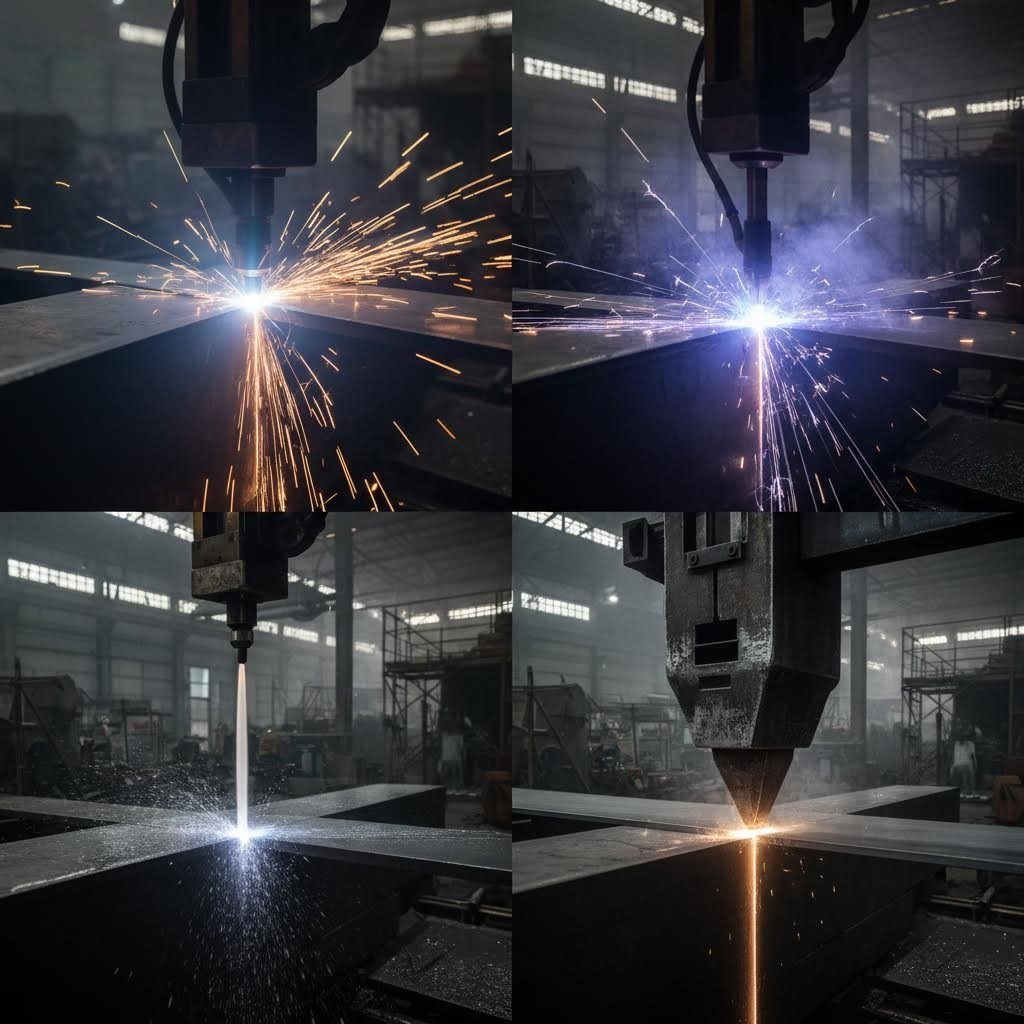
Laser Cutting vs Waterjet Plasma and Mechanical Alternatives
Here's a question that saves manufacturers thousands of dollars: is laser cutting actually the right choice for your project? While a metal laser cutter delivers exceptional precision and speed for many applications, it's not universally superior. Plasma excels at thick steel plate work. Waterjet handles materials that can't tolerate heat. Mechanical shearing offers unbeatable economy for simple straight cuts.
Choosing the wrong cutting metal machine for your application means overpaying for capabilities you don't need—or worse, compromising part quality because you've forced a technology beyond its sweet spot. Let's break down when each method earns its place in your production strategy.
| Factor | Laser Cutting | Plasma Cutting | Waterjet Cutting | Mechanical Cutting |
|---|---|---|---|---|
| Precision/Tolerance | ±0.1mm to ±0.25mm | ±0.5mm to ±1.5mm | ±0.1mm to ±0.25mm | ±0.5mm to ±1.0mm |
| Cutting Speed (thin material) | Excellent | Good | Slow (5-20 in/min) | Very Fast |
| Cutting Speed (thick material) | Moderate | Excellent (100+ in/min on 1/2" steel) | Slow | Limited thickness |
| Material Range | Metals, some plastics/wood | Conductive metals only | Any material | Metals, plastics |
| Max Thickness Capacity | Up to 25-50mm (steel) | Up to 160mm | 150mm+ | 6-12mm typical |
| Heat-Affected Zone | Minimal | Significant | None | None |
| Edge Quality | Excellent (smooth, oxide-free possible) | Good (some dross) | Good (slight texture) | Moderate (burrs possible) |
| Equipment Cost | $150,000-$1,000,000+ | $15,000-$300,000 | $100,000-$500,000 | $10,000-$100,000 |
| Operating Cost/Part | Moderate | Low | High (abrasives) | Very Low |
Laser vs Plasma for Thick Steel Applications
When you're cutting steel plate beyond 10mm, the laser versus plasma debate gets interesting. A cutting machine laser handles thick material competently—high-power fiber systems cut 50mm steel plate routinely. But competent doesn't always mean optimal.
Consider speed: plasma cutting processes 1/2" mild steel at speeds exceeding 100 inches per minute. That's significantly faster than laser on equivalent thickness. For structural fabrication, shipbuilding, or heavy equipment manufacturing where you're processing hundreds of thick plates daily, plasma's throughput advantage translates directly to lower cost per part.
Plasma also brings practical advantages for heavy plate work:
- Bevel cutting capability: Plasma torches tilt for weld preparation, eliminating secondary machining operations
- Lower equipment investment: CNC plasma tables start around $15,000-$300,000 compared to $150,000+ for industrial laser cutting machine for metal systems
- Reduced operating costs: Plasma consumables cost significantly less per inch of cut than laser consumables and electricity combined
However, plasma's heat-affected zone runs wider, and edge quality on thin materials can't match laser precision. Modern high-definition plasma systems achieve near-laser quality on many applications, particularly on materials over 1/4" thick—but for intricate patterns in thin gauge metal, laser remains the clear winner.
The sweet spot? Metal cutting machine selection often comes down to your dominant material thickness. Shops primarily cutting 0.5-6mm material favor laser. Those processing 12mm+ steel plate regularly find plasma delivers better production economics.
When Waterjet Beats Laser Cutting
Waterjet cutting occupies a unique position: slower than laser and plasma, but capable of things neither thermal process can touch. Operating at pressures up to 90,000 PSI, waterjet systems cut virtually any material—metals, glass, stone, composites, ceramics—without generating heat.
That zero-heat characteristic matters enormously for:
- Heat-sensitive materials: Titanium alloys used in aerospace, hardened tool steels, and tempered materials maintain their metallurgical properties because no thermal distortion occurs
- Composite materials: Carbon fiber, fiberglass, and laminated materials cut cleanly without delamination or edge damage
- Reflective metals: While modern metal cutting laser systems handle aluminum and copper, waterjet avoids reflectivity challenges entirely
- Thick non-ferrous metals: Cutting 6" aluminum or brass becomes practical where laser power requirements would be prohibitive
The tradeoffs? Waterjet systems typically cut at 5-20 inches per minute—dramatically slower than laser on thin materials. Operating costs run higher due to abrasive consumption (garnet is the standard medium). And the process generates significant noise, water cleanup requirements, and abrasive handling logistics.
For applications requiring absolute material integrity—aerospace components, medical implants, or any part where heat-affected zones create certification problems—waterjet justifies its slower pace and higher operating costs.
Mechanical Cutting: The Overlooked Option
Before defaulting to thermal or abrasive cutting, consider whether your parts even need them. Mechanical shearing and punching deliver unmatched economy for appropriate applications. Simple straight cuts across sheet metal? A shear produces clean edges at fractions of the cost per cut. High-volume holes in standard patterns? Turret punching outpaces laser for repetitive features.
Mechanical shearing excels at large-scale production and materials like sheet metal, offering speed and simplicity for straight cuts in high volumes. The limitation lies in geometry—complex curves, intricate patterns, and tight-tolerance features require more sophisticated approaches.
Your Decision Framework
Matching technology to project requirements prevents both overspending and underperformance. Use this framework to guide your selection:
- High volume, thin material, complex geometry: Metal cutting laser delivers speed, precision, and automation integration
- High volume, thick steel plate, structural fabrication: Plasma cutting maximizes throughput at lowest cost per part
- Heat-sensitive or exotic materials, any thickness: Waterjet preserves material properties despite slower speeds
- Simple geometries, very high volume: Mechanical cutting offers unbeatable economy for appropriate shapes
- Mixed materials, moderate volume: CO2 laser handles metals and non-metals on one platform
- Tight budget, occasional thick steel: Plasma provides capable cutting at accessible equipment costs
Many production environments benefit from multiple technologies. A job shop might use laser for precision work under 10mm, plasma for heavy plate, and outsource occasional waterjet jobs for specialty materials. The goal isn't finding one perfect solution—it's matching each project to its optimal process.
Understanding technology tradeoffs positions you for smarter conversations with fabricators. But knowing which technology applies still leaves the practical question: what will your parts actually cost?
Cost Factors and Pricing Strategies for Laser Cutting Projects
You've selected the right laser type, confirmed your material compatibility, and optimized your design. Now comes the question that determines whether your project moves forward: what will it actually cost? Understanding laser cutting pricing isn't just about getting competitive quotes—it's about making informed decisions that balance quality, speed, and budget across your entire production strategy.
Here's what many buyers miss: laser cutting costs aren't determined by a single factor. Material type, thickness, design complexity, cutting time, and finishing requirements all contribute to your final price. Master these variables, and you'll know exactly which levers to pull when optimizing project economics.
Breaking Down Per-Part Pricing Factors
What makes one laser cutting quote dramatically different from another? Several interconnected variables drive pricing, and understanding each helps you anticipate costs before requesting quotes.
Material type and thickness establish your pricing baseline. Different materials have unique properties affecting cutting speed, energy consumption, and equipment wear. Cutting stainless steel requires more energy and time compared to carbon steel of equivalent thickness, making it inherently more expensive. Soft or thin materials cut faster and cost less per piece.
Thickness compounds this effect significantly. Thicker materials require more energy and slower cutting speeds to achieve clean penetration. A 10mm steel part might cost three to four times more than the same geometry in 2mm material—not because of raw material alone, but because cutting time multiplies dramatically.
Design complexity directly impacts machine time. Every cutout requires a pierce point where the laser initiates the cut. More pierce points and longer cutting paths increase cutting time and energy, raising overall cost. Intricate designs with numerous small features demand greater precision, adding to labor and equipment expenses.
Consider two parts with identical outer dimensions: one is a simple rectangle, the other features 50 internal holes and decorative cutouts. The complex part might cost five times more despite using the same material quantity—because cutting time, not material, dominates the equation.
Quantity and setup costs create per-unit pricing dynamics that reward volume. Every job involves fixed setup time: programming, material loading, machine calibration, and quality verification. Whether you're cutting 10 parts or 1,000, setup costs remain relatively constant. Spread across more units, your per-piece price drops substantially.
Secondary operations add predictable cost layers. Processes like chamfering, threading, deburring, and surface finishing require additional labor, specialized equipment, and extended production time. Parts needing specific mechanical features or high-quality finishes increase the complexity and duration of manufacturing, raising total costs.
Turnaround time introduces the speed premium. Rush orders requiring expedited processing typically command 25-50% premiums over standard lead times. When deadlines allow flexibility, standard scheduling delivers better pricing.
Volume Discounts and Production Economics
How much can you actually save by ordering smarter? Bulk ordering significantly reduces per-unit costs by spreading fixed setup expenses over more pieces. Larger batch sizes also improve production efficiency, reducing machine downtime between jobs and optimizing material utilization.
Beyond volume discounts, several strategies help control laser cutting expenses:
- Design simplification: Reduce the number of cutouts and simplify geometries to minimize cutting time. Each eliminated pierce point saves machine seconds that accumulate across production runs.
- Material nesting efficiency: Efficient nesting maximizes material usage by arranging parts closely together, minimizing waste and reducing cutting time. Advanced nesting software optimizes layouts, enhancing efficiency and reducing scrap significantly.
- Batch ordering: Consolidate multiple part numbers into single production runs when possible. Ordering several weeks' worth of components at once beats placing weekly small orders—even accounting for inventory carrying costs.
- Appropriate tolerances: Specifying tighter tolerances than your application requires adds cost through slower cutting speeds and increased inspection time. Match precision requirements to actual functional needs.
- Avoid double-cut lines: If a line overlays another in your design file, the laser will double-mark the area, counting as additional cutting time. Review design files to eliminate overlapping paths.
- Prototype before production: A small trial run reveals complications that cost less to fix than discovering issues in a full production order.
In-House Equipment vs. Outsourcing
A question that surfaces regularly: how much is a laser cutting machine, and does owning one make sense? The answer depends on your volume, variety, and operational capacity.
Industrial laser cutting machine price ranges span dramatically based on capability:
- Entry-level fiber systems (1-2kW): $50,000-$150,000
- Mid-range production equipment (3-6kW): $150,000-$400,000
- High-power industrial systems (10kW+): $400,000-$1,000,000+
A small laser cutting machine suitable for light production or prototyping starts around $30,000-$80,000, though these laser cutting machine small systems typically limit you to thinner materials and slower speeds. For serious production work, expect investments in the six-figure range.
But equipment cost represents only part of the equation. On-site laser cutting involves expensive investments in equipment, thorough training, and ongoing maintenance. The machinery demands regular upkeep that raises costs further—safety requirements, repairs, and dedicated floor space all factor into true ownership costs.
When does outsourcing win? Unless your volume justifies dedicated equipment running multiple shifts, enlisting experienced outside fabricators saves space, time, and money. They maintain current equipment, employ trained operators, and spread overhead across multiple customers—efficiencies individual buyers can't match at low-to-moderate volumes.
Conversely, high-volume operations with consistent work and technical expertise often find equipment ownership pays for itself within two to three years through eliminated outsourcing margins and improved production control.
For those exploring sheet metal cutting machine investments, laser cutting machine for sale options range from new OEM equipment to certified used systems that offer capable performance at 40-60% of new pricing. The used market deserves consideration for budget-conscious buyers willing to accept slightly older technology.
Whether you're evaluating quotes from service providers or modeling in-house equipment ROI, understanding these cost drivers positions you to make decisions that optimize both quality and budget. The next step? Finding the right partner to execute your production strategy.
Selecting the Right Laser Cutting Partner for Your Project
You've mapped out your design, confirmed material compatibility, and budgeted for production. Now comes a decision that determines whether your project succeeds or stumbles: choosing who actually cuts your parts. Whether you're searching for steel fabricators in your region or evaluating distant specialists, the wrong partner delivers headaches—missed deadlines, quality failures, and costs that spiral beyond quotes.
The right partner? They become an extension of your engineering team, catching design issues before they become production problems and delivering parts that fit the first time. Here's how to tell the difference before signing a purchase order.
Evaluating Equipment and Capabilities
When researching "sheet metal near me" or "metal fabrication near me," don't stop at proximity. A fabricator's equipment directly limits what they can deliver—and how competitively they can price it.
Start by understanding their laser systems. As California Steel Services notes, different laser cutting technologies impact quality, precision, and speed. Ask specific questions:
- Laser power and type: A shop running 6-12kW fiber lasers handles thick materials and reflective metals that lower-power systems struggle with. Match their capability to your material requirements.
- Bed size: Table dimensions determine maximum part size without repositioning. A 25-foot table accommodates large panels that smaller systems would need to cut in sections.
- Accuracy specifications: Premium systems achieve accuracy of ±0.0005 inches—but only if properly maintained. Ask when equipment was last calibrated.
- Material expertise: Does the fabricator specialize in your specific materials? Experience with stainless steel doesn't automatically translate to aluminum or copper proficiency.
Beyond cutting equipment, evaluate their full capability stack. Some companies offer additional services such as leveling, forming, and slitting. If your project requires powder coating services, bending, welding, or hardware insertion, a one-stop facility streamlines communication and ensures consistency across production stages.
Ask to see sample work. Evaluate the quality of cuts—are edges clean and smooth? Is cutting accurate and precise? Physical samples reveal more than specifications ever could.
Quality Certifications That Matter
Certifications signal that a fabricator has invested in systematic quality management—not just good intentions. For general steel fabrication and metal fabricators near me searches, ISO 9001 certification indicates standardized processes and documented quality controls.
But automotive and aerospace applications demand more. IATF 16949 certification represents the automotive industry's quality management standard, requiring rigorous process controls, defect prevention, and continuous improvement methodologies. Fabrication shops near me serving automotive OEMs need this certification—it's not optional.
Why does certification matter for your project? Consider this: certified facilities undergo regular audits verifying their quality systems function as documented. They maintain traceability records, calibration logs, and corrective action processes. When problems arise—and in manufacturing, they eventually do—certified shops have systematic approaches for identifying root causes and preventing recurrence.
For automotive applications where laser-cut components integrate with stamped assemblies, look for partners demonstrating both cutting expertise and automotive-grade quality systems. Shaoyi (Ningbo) Metal Technology, for example, combines IATF 16949-certified quality with comprehensive manufacturing capabilities for chassis, suspension, and structural components—illustrating the integration between precision cutting and broader automotive supply chain requirements.
Turnaround and Responsiveness
Production timelines matter. A fabricator's turnaround capability affects your entire project schedule.
- Quote responsiveness: How quickly do they respond to RFQs? Partners offering 12-hour quote turnaround demonstrate operational efficiency that typically extends to production.
- Standard lead times: Understand baseline capacity. A shop running three shifts offers different availability than a single-shift operation.
- Rush capability: Faster turnaround times may come at a premium—know what expediting costs before you need it urgently.
- Scalability: Consider whether services can accommodate your project's size and scale, both now and in the future. Growing with a partner beats switching providers mid-project.
DFM Support and Prototyping Capabilities
The best fabricators catch problems before cutting starts. Design for Manufacturability (DFM) assistance—often provided free of charge—ensures designs are fully optimized before production. Expert engineers review drawings, identifying features that might cause cutting issues, distortion during forming, or assembly problems downstream.
This matters especially during product development. Partners offering 1-3 day rapid prototypes allow you to validate designs quickly before committing to production quantities. Contrast this with providers requiring weeks for prototypes—every day of delay pushes your launch date further out.
For automotive programs where timing drives competitiveness, 5-day rapid prototyping capabilities—like those offered by Shaoyi—accelerate development cycles significantly. Combined with comprehensive DFM support, this responsiveness helps engineering teams iterate faster and reach production-ready designs with fewer revision cycles.
When evaluating potential partners, ask directly: What percentage of orders ship on time? Top performers achieve 96% on-time delivery annually—a metric that speaks louder than promises.
Finding the right laser cutting partner takes research, but the investment pays dividends throughout your production relationship. With partner selection criteria established, let's look ahead to emerging technologies reshaping the industry—and concrete steps for launching your next project.
Future Trends and Your Next Steps in Laser Cutting
You've navigated the fundamentals—laser types, material compatibility, precision standards, design guidelines, and partner selection. Now the question becomes: where is laser sheet metal cutting headed, and how do you apply everything you've learned to your next project? The industry isn't standing still. Advances in power, intelligence, and automation are reshaping what's possible, while practical steps today position you for success tomorrow.
Emerging Technologies Reshaping the Industry
The sheet metal laser cutter you evaluate today looks dramatically different from systems installed just five years ago. Several converging trends are accelerating this evolution.
High-power fiber lasers continue pushing boundaries. Systems rated at 10kW, 20kW, and even 30kW and beyond now enable cuts through materials thicker than 50mm without compromising speed. For heavy fabrication—automotive structural components, shipbuilding, and industrial equipment—these high-power systems deliver throughput that previously required plasma cutting, but with laser-quality edge finish. The practical impact? Jobs that once demanded multiple technologies now consolidate onto a single sheet metal laser cutting machine.
AI and machine learning integration represents perhaps the most transformative shift. AI is revolutionizing laser cutting by enabling systems to adapt to different materials and working conditions. With real-time data analysis, these intelligent systems optimize cutting parameters—laser power, speed, and focus—automatically. The result? Improved precision, fewer errors, and reduced operator intervention. Companies like Trumpf already deploy AI to fine-tune parameters for various materials, achieving faster cutting times and reduced material waste.
What does this mean practically? Imagine a laser sheet metal cutter that recognizes material variations within the same batch and compensates automatically. Or systems that predict maintenance needs before failures occur, minimizing unplanned downtime. AI-driven systems are expected to become self-learning, predicting potential issues and preventing downtime by detecting faults before they occur.
Automation and robotic integration extend beyond the cutting head itself. Automated systems and robotic arms can load and unload materials, handle parts, and even perform quality control tasks, significantly reducing manual labor requirements. BMW's production plants exemplify this approach—robots work alongside laser cutting systems for tasks from cutting car parts to assembling intricate components, creating faster, more efficient manufacturing processes.
Real-time quality monitoring closes the feedback loop. Modern systems incorporate sensors that verify cut quality during production, not just after. Dimensional checks, thermal imaging, and surface analysis happen in-process, catching deviations before they become scrapped parts. This capability proves especially valuable for high-value materials or critical applications where every rejected part carries significant cost.
Sustainability improvements address both operating costs and environmental concerns. Fiber lasers use less energy and produce minimal waste, aligning with global environmental standards. For manufacturers facing pressure to reduce carbon footprints while controlling costs, these efficiency gains deliver dual benefits.
The most successful sheet metal laser cutting projects don't start with technology—they start with clearly defined requirements. Match your precision needs, material specifications, volume expectations, and timeline to the right cutting approach and manufacturing partner, and the technology becomes a tool rather than a constraint.
Your Action Plan for Laser Cutting Success
Theory without application stays theory. Here's a concrete roadmap for translating everything in this guide into production-ready parts:
- Define your project requirements precisely. Document material type and thickness, quantity needed, tolerance requirements, edge quality expectations, and downstream operations (bending, welding, finishing). Be specific—"tight tolerances" means different things to different fabricators. Specify ±0.1mm if that's what you need, or accept ±0.25mm if it's sufficient for your application.
- Request quotes from multiple suppliers. Don't settle for the first response. Compare at least three fabricators, evaluating not just price but lead time, DFM support offerings, and communication responsiveness. Partners offering rapid quote turnaround—some manufacturers like Shaoyi provide 12-hour quote turnaround—demonstrate operational efficiency that typically extends to production execution.
- Evaluate DFM feedback carefully. The best fabricators don't just quote your design—they improve it. Pay attention to suggestions about feature sizing, material selection, tolerance optimization, and cost reduction opportunities. Manufacturers offering comprehensive DFM support catch problems before cutting starts, saving revision cycles and accelerating your timeline.
- Start with prototype quantities. Before committing to production volumes, validate your design with a small trial run. Modern fibre laser technology achieves accuracy within ±0.1mm, but real-world verification reveals complications that even careful analysis might miss. Prototypes cost less than production rework.
- Verify quality systems and certifications. For automotive applications, confirm IATF 16949 certification. For general metal fab work, ISO 9001 provides baseline assurance. Ask about inspection processes, traceability documentation, and on-time delivery track records.
- Plan for scale. Consider whether your selected partner can grow with your needs. A fabricator handling 100-piece prototypes efficiently may struggle with 10,000-piece production runs—or vice versa. Discuss volume capabilities and lead time expectations at different quantities upfront.
The global laser cutting market continues expanding—projected to nearly double from USD 7.12 billion in 2023 to USD 14.14 billion by 2032. This growth reflects the technology's fundamental value proposition: unmatched precision, speed, and versatility for modern manufacturing. Whether you're producing automotive chassis components, architectural panels, or precision medical devices, sheet metal laser cutting delivers capabilities that mechanical methods simply cannot match.
Your next step? Take action. Define those requirements, request those quotes, and move your project from planning to production. The technology is ready. The partners are available. The only remaining variable is your decision to start.
Frequently Asked Questions About Laser Sheet Metal Cutting
1. Can you laser cut sheet metal?
Yes, laser cutting is one of the most effective methods for processing sheet metal. The process uses a highly concentrated beam of light focused to an intensity high enough to melt or vaporize metals like steel, aluminum, brass, and copper. Modern fiber lasers excel at cutting both ferrous and non-ferrous metals with exceptional precision, achieving tolerances as tight as ±0.1mm. The technology handles material thicknesses ranging from thin gauge sheets under 1mm to heavy plates exceeding 50mm with high-power systems.
2. How much does metal laser cutting cost?
Laser cutting costs depend on multiple factors including material type, thickness, design complexity, quantity, and turnaround time. Hourly rates typically range from $13-$20 for steel cutting. Thicker materials require more energy and slower speeds, increasing costs significantly. Complex designs with many pierce points and intricate cutouts cost more than simple geometries. Volume discounts reduce per-unit costs by spreading fixed setup expenses across more pieces. Secondary operations like bending, deburring, and powder coating add predictable cost layers to your total project expense.
3. What is the cost of a laser cutting metal sheet machine?
Industrial laser cutting machine prices vary dramatically based on power and capability. Entry-level fiber systems rated 1-2kW range from $50,000-$150,000. Mid-range production equipment at 3-6kW costs $150,000-$400,000. High-power industrial systems at 10kW and above can exceed $400,000-$1,000,000. Small laser cutting machines suitable for light production start around $30,000-$80,000 but limit you to thinner materials and slower speeds. Beyond purchase price, factor in training, maintenance, safety requirements, and dedicated floor space for true ownership costs.
4. How thick of steel can a 1000W laser cut?
A 1000W fiber laser typically cuts mild steel up to 6mm and stainless steel up to 4mm with acceptable edge quality. Aluminum thickness capacity reaches approximately 3mm due to its high reflectivity and thermal conductivity. As you scale to higher power levels, capabilities expand significantly: 2kW handles 10mm mild steel, 6kW reaches 20mm, and 10kW+ systems can cut through 50mm or more. Material properties, assist gas selection, and desired edge quality all influence the practical maximum thickness for any given power level.
5. What is the difference between fiber and CO2 lasers for metal cutting?
Fiber lasers operate at a shorter wavelength (~1.06 µm) that metals absorb more readily, delivering 1.3-2.5x faster cutting speeds on thin materials compared to CO2 lasers. They consume 30-50% less electricity and require minimal maintenance without mirrors or lenses. CO2 lasers with their longer 10.6 µm wavelength excel at cutting non-metals like wood, acrylic, and textiles alongside metals, making them ideal for mixed-material shops. For dedicated metal cutting, fiber lasers dominate new installations, while CO2 retains its niche in versatile applications requiring both metal and non-metal processing.