 Small batches, high standards. Our rapid prototyping service makes validation faster and easier —

CNC Metal Forming Decoded: 7 Techniques That Cut Costs Fast
What CNC Metal Forming Actually Means for Modern Manufacturing
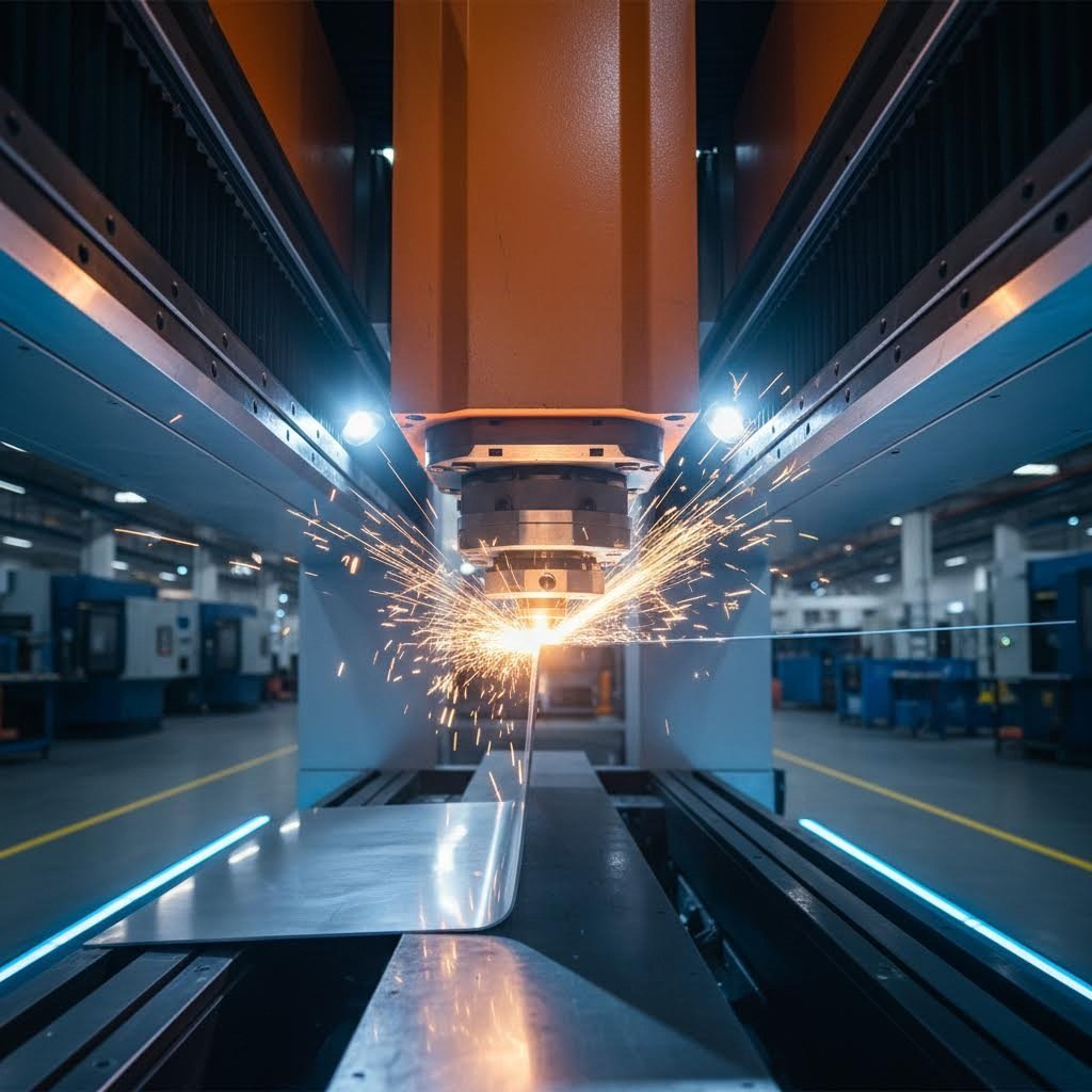
Ever watched a flat sheet of metal transform into a perfectly angled bracket or a complex automotive component? That transformation happens through CNC metal forming, a process that has fundamentally changed how manufacturers approach metal fabrication. Whether you're running a high-volume production line or working on custom projects in your shop, understanding this technology gives you a serious edge.
CNC metal forming is the process of turning sheet metal into three-dimensional parts by exerting applied force through computer-controlled machinery, where critical parameters like bend depth, pressure, and sequence are programmed for precise repeatability.
From Raw Sheet to Precision Part
Imagine feeding a flat aluminum sheet into a machine and watching it emerge as a perfectly formed enclosure with multiple bends, each hitting exact specifications. That's what CNC forming delivers. The process uses programmed toolpaths to apply force at precise locations, reshaping metal without removing material. Unlike cutting operations, forming manipulates the sheet's geometry while preserving its structural integrity.
The force applied must exceed the metal's yield strength to permanently change its shape. Press brakes, for instance, use a punch and V-shaped die system to create bends with microform precision that manual methods simply cannot match consistently. This level of accuracy becomes critical when you're producing parts that need to fit together in assemblies or meet strict tolerance requirements.
The Digital Revolution in Metal Shaping
What separates CNC forming from traditional metalworking? Control. Every parameter that affects your final part, including bend angle, depth, pressure, and sequence, gets stored digitally. Run a job today, and you can repeat it perfectly six months from now. This repeatability eliminates the guesswork that plagued manual operations and reduces the dependency on a single skilled operator's expertise.
Metal forming machinery equipped with CNC capabilities works seamlessly with CAD and CAM software. You design your part, simulate the bends, and send instructions directly to the machine. When specifications change, you update the program rather than retraining operators or creating new physical templates.
How Computer Control Transforms Metal Forming
The range of CNC forming techniques available today extends far beyond basic bending. This article covers seven distinct methods, from air bending and bottoming to hydroforming and incremental forming. Each technique serves different applications, material thicknesses, and production volumes.
For professional manufacturers, these techniques enable everything from aerospace structural components to automotive chassis parts. For makers and hobbyists, accessible CNC forming opens doors to projects that once required expensive outsourcing. The technology bridges both worlds, delivering microform precision whether you're producing thousands of identical brackets or crafting a single custom piece. Understanding which technique fits your project requirements is the first step toward smarter, more cost-effective manufacturing.
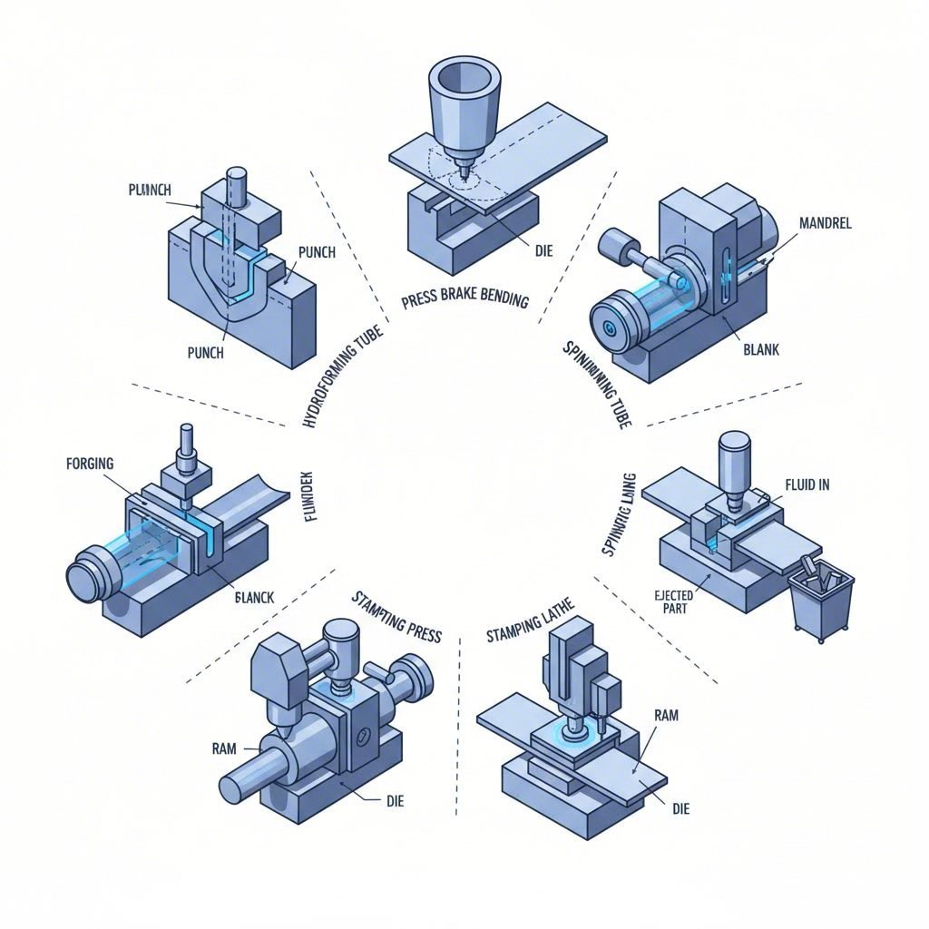
Seven CNC Metal Forming Techniques Compared
So you know what CNC metal forming can do, but which technique should you actually use? That depends on your part geometry, production volume, and budget. Most manufacturers specialize in one or two methods, which means they'll recommend what they offer rather than what works best for your project. Let's break down all seven major techniques so you can make an informed decision.
Air Bending vs Bottoming vs Coining
These three CNC bending methods represent the core of press brake operations, and understanding their differences saves you money and headaches. Think of them as a spectrum from flexibility to precision.
Air bending is the most common approach in modern sheet metal forming machine operations. The punch presses the material into the die without making full contact at the bottom. You're essentially creating a bend angle based on how deep the punch travels. The advantage? You can achieve multiple angles with a single die set. The trade-off is springback, where the metal partially returns toward its original flat state after pressure releases. Skilled CNC programming compensates for this, but expect tolerances around ±0.5 degrees.
When tighter accuracy matters, bottoming steps in. Here, the punch forces the material fully into the die cavity, creating contact along the entire bend line. This method reduces springback significantly and delivers tolerances around ±0.25 degrees. However, you'll need higher tonnage and specific die angles for each bend you want to produce.
Coining takes precision to another level. After the material contacts the die, additional force essentially stamps the bend into permanent shape. According to Inductaflex's technical documentation, coining adds force after contact to virtually eliminate springback. You'll achieve the tightest tolerances possible, but tooling wear increases substantially, and the tonnage requirements can be five to eight times higher than air bending.
When Hydroforming Outperforms Traditional Methods
Ever wondered how manufacturers create those seamless tubular components or complex curved panels without visible weld lines? Hydroforming uses pressurized fluid to push metal against a die cavity, enabling 3D forming that conventional press brakes cannot achieve.
This technique excels at producing lightweight structural parts with consistent wall thickness. Automotive manufacturers rely heavily on hydroforming for frame rails, exhaust components, and suspension parts. The process handles both sheet metal and tubular stock, making it versatile for different applications.
The catch? Hydroforming requires specialized metal forming machines with hydraulic systems capable of generating extreme pressures. Tooling costs run higher than press brake dies, and cycle times tend to be longer. For high-volume production of complex geometries, though, the per-part economics often favor hydroforming over multi-step welded assemblies.
Spinning offers another specialized approach, rotating sheet metal against a mandrel to create axially symmetric parts. Think of satellite dishes, cookware, or decorative light fixtures. CNC-controlled spinning produces consistent results across production runs, though it's limited to round or conical shapes.
Incremental Forming for Complex Geometries
What if you need a complex 3D shape but can't justify expensive hydroforming tooling? Incremental forming fills this gap brilliantly. A CNC-controlled stylus or forming tool progressively pushes the sheet metal through a series of small deformations, gradually building the final geometry without dedicated dies.
This technique shines in prototyping and low-volume production. You can program virtually any shape directly from CAD files, eliminating tooling lead times. General forming corporation facilities and specialized job shops increasingly offer incremental forming for applications ranging from medical device housings to architectural panels.
The limitation is speed. Incremental forming traces the entire surface area, making it impractical for high volumes. Surface finish also differs from stamped parts, sometimes requiring secondary operations.
Stamping rounds out the major techniques, using matched die sets to form parts in a single press stroke. For production runs in the thousands or millions, stamping delivers the lowest per-part cost. Progressive dies can perform multiple operations, including cutting, forming, and piercing, in one cycle. The tooling investment is substantial, but amortized across high volumes, stamping remains unbeatable for efficiency.
| Technique | Precision Level | Material Thickness Range | Production Volume | Tooling Cost | Typical Applications |
|---|---|---|---|---|---|
| Air Bending | ±0.5° | 0.5mm – 25mm | Low to Medium | Low | Brackets, enclosures, general fabrication |
| Bottoming | ±0.25° | 0.5mm – 12mm | Medium | Medium | Precision brackets, visible parts |
| Coining | ±0.1° | 0.3mm – 6mm | Medium to High | High | Electrical contacts, precision components |
| Hydroforming | ±0.2mm | 0.5mm – 4mm | Medium to High | High | Automotive frames, tubular structures |
| Spinning | ±0.3mm | 0.5mm – 6mm | Low to Medium | Medium | Domes, cones, reflectors |
| Incremental Forming | ±0.5mm | 0.5mm – 3mm | Prototyping/Low | Very Low | Prototypes, medical devices, custom parts |
| Stamping | ±0.1mm | 0.2mm – 8mm | High Volume | Very High | Automotive panels, appliance parts, electronics |
Choosing between these techniques isn't just about capability. It's about matching your project's volume, complexity, and budget to the right process. A general forming corporation handling diverse orders might use several methods depending on the job, while specialized shops focus on perfecting one technique. Now that you understand the forming options, the next critical decision involves selecting the right material for your specific application.
Material Selection Guide for CNC Forming Success
You've chosen your forming technique, but here's the thing: even the most advanced sheet metal press won't deliver quality parts if you're working with the wrong material. Metal selection directly impacts everything from bend accuracy to surface finish, and getting it wrong means scrapped parts, wasted time, and blown budgets. Let's walk through what actually matters when selecting materials for CNC sheet metal operations.
Aluminum Alloys and Their Forming Characteristics
Aluminum dominates CNC forming applications for good reason. It's lightweight, corrosion-resistant, and bends without excessive force. But not all aluminum alloys behave the same way under a metal shaping machine.
The 5000-series alloys, particularly 5052, rank among the most formable options. According to ProtoSpace's technical guidelines, 5052 aluminum requires compensation for approximately 2 to 5 degrees of springback when working with bend radii between 0.4 and 2 times the material thickness. This alloy offers excellent corrosion resistance and welds easily using MIG or TIG methods, making it ideal for enclosures and marine applications.
- 5052 Aluminum: High formability, excellent weldability, good corrosion resistance, moderate strength
- 5083 Aluminum: Highest strength among non-heat-treatable alloys, superior seawater resistance, not recommended above 65°C
- 6061 Aluminum: Precipitation-hardened, good mechanical properties, commonly extruded, moderate formability
- 6082 Aluminum: Medium strength, very good weldability and thermal conductivity, formed by rolling and extrusion
- 7020 Aluminum: High strength-to-weight ratio, good fatigue resistance, high structural strength suitable for load-bearing applications
The 6000-series alloys like 6060 and 6061 offer a balance between strength and formability. 6060 is specifically suited for cold forming operations, while 6061's precipitation-hardened structure provides better mechanical properties at the cost of slightly reduced bendability. For aerospace applications requiring maximum strength, 7020 aluminum delivers exceptional performance, though its forming characteristics demand more careful programming.
Steel Selection for Optimal Bend Quality
Steel remains the workhorse material in sheet metal CNC fabrication, but the carbon content dramatically affects how it behaves during forming. Lower carbon means easier bending; higher carbon delivers strength but fights back during the process.
Cold-rolled steel (CRS) offers the best formability among steel options. The springback characteristics are notably lower than aluminum, with industry data indicating only 1 to 3 degrees of compensation needed for typical bend radii. This predictability makes CRS a favorite for brackets, enclosures, and structural components where weldability matters.
- DC01 Cold-Rolled Steel: Non-alloy, very low carbon, highly ductile, easy to weld, braze, and solder
- S235JR Structural Steel: Good plasticity and toughness, lower yield strength, excellent weldability
- S355J2 High-Strength Steel: Designed for high-stress applications, exceptional resilience and durability
- C45 Medium Carbon Steel: 0.42-0.50% carbon content, high wear resistance, lower ductility, case-hardenable
Stainless steel introduces additional considerations. Grades 304 and 316 are austenitic chromium-nickel alloys with excellent corrosion resistance but require more forming force and exhibit greater springback. Expect 3 to 5 degrees of springback for 304 stainless, according to forming specialists. The 316 grade, with its molybdenum addition, handles chloric environments better but shares similar forming challenges.
For sheet metal cnc applications, Protolabs maintains a standard tolerance of ±1 degree on all bend angles, with minimum flange lengths at least 4 times the material thickness. These specifications apply across steel grades, though achieving them becomes easier with lower-carbon materials.
Working with Copper and Brass
When electrical conductivity or aesthetic requirements drive your material choice, copper and brass enter the conversation. Both form readily but demand attention to surface quality and work hardening.
Copper's exceptional electrical and thermal conductivity makes it essential for electrical components and heat exchangers. It bends smoothly with minimal springback, but the soft surface scratches easily during handling. Protective films and careful tooling maintenance become mandatory for visible applications.
- Copper: Excellent electrical/thermal conductivity, low springback, soft surface prone to scratching, work hardens progressively
- Brass (70/30): Good formability, attractive gold appearance, higher strength than pure copper, corrosion-resistant
- Brass (60/40): Better machinability, reduced cold-forming capability, suitable for decorative applications
Brass alloys vary significantly in their forming characteristics based on zinc content. The 70/30 composition (70% copper, 30% zinc) offers superior cold formability compared to 60/40 brass, which machines better but resists bending. Both materials work harden during forming, meaning multiple bends may require intermediate annealing to prevent cracking.
Thickness considerations apply universally across materials. Thicker stock generally exhibits less springback because the increased material mass resists elastic recovery more effectively. However, thicker materials require proportionally higher forming forces and larger minimum bend radii to prevent cracking. For materials 0.036 inches or thinner, holes should maintain at least 0.062 inches from material edges; thicker stock needs 0.125 inches minimum clearance to avoid distortion during forming.
The grain direction relative to your bend lines matters more than many operators realize. Bending perpendicular to the grain direction improves accuracy and significantly reduces cracking risk. When your design requires bends parallel to the grain, increase bend radii and consider specifying annealed tempers to compensate.
With your material selected and its properties understood, the next challenge is translating your design into machine instructions. That's where CAM software and toolpath programming become critical to achieving the results your material selection makes possible.
Programming CNC Metal Forming Operations
You've selected your material and understand the forming techniques available. Now comes the step that separates efficient operations from costly trial-and-error: programming. Without proper toolpath programming, even the most capable CNC sheet metal bending machine becomes an expensive paperweight. The software layer between your design and the finished part determines whether you nail specifications on the first attempt or waste material figuring things out.
Here's what many operators discover the hard way: a perfect CAD model doesn't automatically translate into a successful formed part. The machine needs explicit instructions about bend sequences, tool positioning, backgauge locations, and motion paths. CAM software bridges this gap, turning geometric data into actionable machine code while preventing costly collisions and optimizing cycle times.
CAM Software Essentials for Metal Forming
Computer-aided manufacturing software serves as the translator between your design intent and machine execution. When you import a 3D model into a CAM program, the software analyzes the geometry and works out how to produce it using available equipment and tooling.
According to Wiley Metal's fabrication specialists, CAM programs import geometry data from part designs and determine optimal manufacturing sequences based on programmer-defined constraints. These constraints might prioritize cycle time reduction, material utilization, or specific quality requirements depending on your production goals.
For CNC metal bending operations, specialized CAM solutions handle the unique challenges of forming. Programs like Almacam Bend automate the complete bending process, including bend sequence calculation, tool selection and positioning, backgauge configuration, and final G-code generation. This automation reduces programming time dramatically while eliminating the manual calculation errors that plague less sophisticated approaches.
What makes forming-specific CAM valuable? The software understands material behavior. It calculates springback compensation, determines minimum bend radii, and accounts for the relationship between punch depth and resulting angle. General-purpose CAM packages designed for milling or routing lack this specialized knowledge.
Professional solutions dominate high-volume manufacturing, but hobbyists and small shops have options too. Several press brake manufacturers bundle programming software with their CNC sheet metal machines, providing accessible entry points without enterprise-level costs. Cloud-based platforms are emerging that offer pay-per-use access to forming simulation and programming tools.
Optimizing Bend Sequences Programmatically
Sounds complex? It doesn't have to be. Think of bend sequence optimization as solving a puzzle where the order of moves matters as much as the moves themselves. Bend a flange too early, and it might collide with the machine during subsequent operations. Choose an inefficient sequence, and your operator spends more time repositioning parts than actually forming them.
Modern CAM software attacks this problem algorithmically. The DELEM DA-69S controller, common on many CNC machine sheet metal systems, offers multiple computation approaches according to Harsle's technical documentation:
- Manual programming: The operator defines each bend step based on experience and part requirements
- Sequence only calculation: Software determines optimal order using existing tool setup
- Sequence plus tool optimization: Adjusts tool positions and stations for improved efficiency
- Sequence plus tool setup: Removes existing tools and calculates the best-fit configuration from the tool library
The optimization degree setting controls how exhaustively the software searches for solutions. Higher settings examine more alternatives, delivering better results at the cost of longer computation time. For complex parts with numerous bends, this trade-off becomes significant.
Backgauge positioning represents another critical optimization target. The software must ensure the sheet rests properly against gauge fingers while avoiding collisions with previously formed flanges. Parameters like minimum finger-product overlap and lay-on backstop limits govern these calculations, preventing the machine from attempting impossible configurations.
Simulation Before First Bend
Imagine running your entire job virtually before touching actual material. That's exactly what modern CNC sheet metal machines enable through integrated simulation capabilities. You'll catch problems that would otherwise destroy parts or damage equipment.
According to Almacam's technical specifications, full 3D simulation of the bending process verifies target accessibility and collision risk at every step of the press brake cycle. The software checks whether the punch can reach the bend line without hitting previously formed geometry, whether the part can be positioned and repositioned between bends, and whether the backgauge can access valid reference points.
The typical workflow from design file to finished part follows a logical progression:
- Import CAD geometry: Load your 3D model or 2D flat pattern into the CAM software
- Define material properties: Specify alloy, thickness, and grain direction for accurate springback calculation
- Select tooling: Choose punch and die combinations from the machine's tool library
- Calculate unfold: Generate the flat pattern with bend allowances if starting from 3D geometry
- Compute bend sequence: Let the software determine optimal order or define manually
- Run collision simulation: Verify each step executes without interference
- Generate CNC program: Post-process the verified sequence into machine-specific G-code
- Transfer and execute: Send the program to the CNC sheet metal bending machine
The simulation phase catches issues like product-product collisions, where a flange might intersect with another part of the workpiece during manipulation. Controllers like the DELEM DA-69S allow configuring collision detection as disabled, treated as a warning, or treated as an error depending on your quality requirements.
For shops running multiple CNC sheet metal machines from different manufacturers, unified CAM platforms provide significant advantages. A single programming interface handles various equipment, allowing engineers to switch jobs between machines without learning different software packages. Post-processors translate the common toolpath format into the specific G-code dialect each controller expects.
Virtual fabrication capabilities continue advancing rapidly. Digital twin technology promises to replicate not just geometry but the physical behavior of specific machines, tooling wear patterns, and material lot variations. As Wiley Metal notes, these developments will reduce waste, improve accuracy, and enable production of complex forms even for one-off projects.
With your programming workflow established and simulations confirming feasibility, the final piece of the puzzle is designing parts that form successfully in the first place. That's where Design for Manufacturability principles separate amateur designs from production-ready ones.

Design for Manufacturability in CNC Forming
Here's a hard truth: the most expensive part in any CNC sheet metal fabrication project is the one you have to remake. Bad designs don't just slow you down—they drain budgets, frustrate operators, and push deadlines into the danger zone. The good news? Most forming failures trace back to a handful of preventable design mistakes.
Design for Manufacturability, or DFM, is exactly what it sounds like: engineering your parts so they're easy to produce. When you design with forming constraints in mind from the start, you eliminate the costly back-and-forth between engineering and the shop floor. Let's walk through the critical rules that separate production-ready designs from expensive learning experiences.
Critical Dimensions Near Bend Lines
Ever noticed holes stretching into ovals after bending? That's what happens when features sit too close to fold lines. The metal flowing during deformation distorts anything in the stress zone, turning round holes into useless shapes that won't accept fasteners properly.
According to Norck's DFM guidelines, holes placed too close to bend locations will stretch and deform, making it impossible to pass screws or pins through. The fix is straightforward but non-negotiable:
- Hole placement rule: Keep all holes at least 2 times the material thickness away from any bend line
- Slot orientation: Position elongated cutouts perpendicular to bend lines when possible to minimize distortion
- Feature sizing: Narrow slots and cutouts should be at least 1.5 times wider than the sheet thickness to prevent heat-induced warping during laser cutting
- Edge clearance: For materials 0.036 inches or thinner, maintain 0.062 inches minimum from edges; thicker stock needs 0.125 inches
What about countersinks near bends? These recessed features for flat-head fasteners create particular headaches. According to Xometry's engineering guidelines, countersinks placed too close to bends or edges cause deformation, misalignment, or cracking—especially in thin or hard materials. Position them well away from forming zones or consider alternative fastening strategies.
Minimum Flange Heights and Leg Lengths
Imagine trying to fold a tiny sliver of paper with your fingers. That's essentially what sheet metal forming machines face when flanges are too short. The tooling needs enough material to grip and form properly, and violating this principle leads to incomplete bends, warped parts, or damaged equipment.
The fundamental rule from Norck's fabrication standards: make flanges at least 4 times as long as the metal is thick. Shorter "illegal" flanges require custom, expensive molds that can double production costs.
Specific minimum leg lengths vary by material and thickness. Here's what the data shows for air bending with standard V-dies:
- Steel/Aluminum at 1mm thickness: 6mm minimum leg length
- Steel/Aluminum at 2mm thickness: 10mm minimum leg length
- Steel/Aluminum at 3mm thickness: 14mm minimum leg length
- Stainless steel at 1mm thickness: 7mm minimum leg length
- Stainless steel at 2mm thickness: 12mm minimum leg length
For coining or bottom bending, slightly shorter legs become feasible because these methods apply greater forming force. However, designing to the air bending minimums gives you flexibility across different sheet metal former equipment and techniques.
Designing for Springback Compensation
Metal doesn't forget where it came from. When forming pressure releases, your material wants to spring back toward its original flat state. This elastic recovery affects every bend you make, and ignoring it guarantees parts that don't meet spec.
According to Dahlstrom Roll Form's engineering guide, knowing how to overcome springback is less about prevention and more about preparation. The main predictors are yield point and elastic modulus, and the solution is typically overforming—bending slightly past your target angle so the material springs back to the desired position.
An approximate formula estimates springback angle: Δθ = (K × R) / T, where K represents a material constant, R is the inside bend radius, and T is material thickness. Different materials exhibit different behaviors:
- Cold-rolled steel: 1-3 degrees of springback compensation typically needed
- Aluminum alloys: 2-5 degrees compensation for standard bend radii
- Stainless steel: 3-5 degrees or more, depending on grade
- High-strength steels: Can exceed 5 degrees, requiring careful programming
Your CNC sheet metal bending program should incorporate these compensations automatically, but you need accurate material data for the calculations to work. Specifying the exact alloy and temper in your documentation prevents the guesswork that leads to rejected parts.
Relief Cuts and Corner Strategies
When a bend line meets a flat edge, trouble brews. The metal wants to tear at that junction because there's nowhere for the stress to go. Relief cuts solve this problem by providing controlled stress release points before disaster strikes.
As Norck's guidelines explain, adding a small rectangular or circular cut-out at the end of bend lines guarantees a clean, professional finish that won't cause parts to break under pressure. This makes your product more resilient for end users.
- Relief cut width: Should equal at least the material thickness
- Relief cut depth: Extend slightly past the bend line to ensure complete stress relief
- Shape options: Rectangular cuts are simplest; circular reliefs reduce stress concentration but require slightly more material removal
- Inside corners: Add fillets rather than sharp intersections to prevent crack initiation
For Z-bends and offset configurations, minimum step heights become critical. The vertical distance between parallel bends must accommodate the lower tool during forming. Steel and aluminum at 2mm thickness typically need 12mm minimum step height; stainless steel at the same thickness requires 14mm.
Grain Direction and Bend Radius Considerations
Metal sheets carry hidden directionality from their manufacturing process. Rolling operations at the mill create a "grain" structure, and bending behavior changes dramatically depending on whether you work with or against it.
The rule is simple according to Norck: design parts so folds happen across the grain, not with it. This hidden rule prevents parts from failing or cracking months after delivery. When bends parallel to the grain are unavoidable, increase your bend radii significantly and consider specifying annealed material tempers.
Speaking of bend radii, the inside curve of your bend should at least match the thickness of the metal. This prevents the outer surface from cracking due to excessive tensile stress. Larger radii improve formability further and reduce springback, especially important for stainless steel and aluminum.
- Minimum inside radius: Equal to material thickness for ductile materials
- Stainless steel: Often requires 1.5-2 times material thickness
- Aluminum 7xxx series: May need 2-3 times thickness due to reduced ductility
- Standardize radii: Using the same radius throughout your design allows single-tool operation, reducing setup time and cost
Common Design Mistakes and Their Solutions
Even experienced engineers make these errors. Recognizing them before you submit files saves everyone headaches:
- Problem: Custom hole sizes like 5.123mm requiring special tooling. Solution: Use standard hole sizes (5mm, 6mm, 1/4 inch) that work with existing punching tools for faster turnaround.
- Problem: Tight tolerances everywhere, driving up inspection costs. Solution: Apply precision requirements only where functionally necessary; allow ±1 degree on non-critical bends.
- Problem: Successive bends creating interference. Solution: Ensure intermediate flat sections are longer than adjacent flanges to prevent collision during forming.
- Problem: Ignoring material-specific behavior. Solution: Document exact alloy, temper, and thickness requirements so the sheet metal former can program appropriately.
Following these DFM principles transforms your designs from "technically possible" to "production-optimized." The investment in upfront design time pays dividends through faster manufacturing, fewer rejects, and lower per-part costs. With your parts designed for success, the next consideration is understanding how CNC methods compare against traditional manual forming—and when each approach makes sense.
CNC Versus Manual Metal Forming Methods
So you've got your design optimized and your material selected. Now comes a question that trips up more manufacturers than you'd expect: should you form these parts on CNC equipment or stick with manual methods? The answer isn't as straightforward as equipment salespeople might suggest.
Both approaches have legitimate places in modern fabrication. Understanding their trade-offs helps you make decisions based on your actual project requirements rather than assumptions or marketing hype. Let's break down what each method delivers and where it falls short.
Repeatability and Precision Advantages
When you need 500 identical brackets with bend angles holding ±0.25 degrees, CNC wins without contest. The machine executes the same programmed toolpath every single time, eliminating the human variability that creeps into manual operations.
According to Jiangzhi's technical comparison, CNC machines can replicate the same part with identical dimensions and quality across multiple batches because the automated process eliminates human error. Once your program is verified, you're essentially copying perfection with each cycle.
This repeatability extends beyond just angle accuracy. Consider these CNC-driven consistency factors:
- Bend location precision: Backgauge positioning holds tight tolerances across hundreds or thousands of parts
- Pressure consistency: Programmed tonnage applies identical force to every bend
- Sequence execution: Multi-bend parts follow the exact same order every time, preventing cumulative errors
- Complex geometry capability: Multi-axis CNC equipment handles intricate compound curves that would challenge even skilled manual operators
The precision advantage becomes particularly pronounced with complex parts. A metal forming machine with CNC control handles intricate, multi-axis designs that would be difficult or impossible to achieve with manual equipment. When your part requires tight tolerances across multiple features, automation delivers reliability that human hands simply cannot match consistently.
When Manual Forming Still Makes Sense
Here's what the CNC advocates don't always mention: for certain applications, traditional methods remain the smarter choice. Ignoring this reality leads to overspending on equipment and setup time that never gets recovered.
Manual forming shines in specific scenarios. Research from the University of Melbourne's manufacturing studies examined robotic versus manual English wheeling and found that while automation enhanced accuracy and repeatability, the manual process allowed skilled craftsmen to form compound curves with a flexibility that rigid automation couldn't easily replicate.
Consider manual methods when facing these situations:
- One-off prototypes: Programming time exceeds forming time for single parts
- Simple bends on few parts: A skilled operator can complete basic work faster than setup allows
- Highly organic shapes: Traditional metal shaping services using techniques like English wheeling offer artistic flexibility
- Repair and modification work: Adjusting existing parts often requires hands-on adaptation
- Budget constraints: Manual machines cost significantly less upfront
The flexibility factor deserves attention. With manual equipment, the machinist has complete control over the process, making it easier to adjust parameters on the fly. This proves especially useful in prototyping, repair, or situations where unique part designs are required. When you're figuring out a design through iteration rather than executing a finalized specification, manual control accelerates the learning process.
Breaking Down the Cost Equation
Cost comparisons between CNC and manual forming aren't as simple as comparing machine prices. The real calculation involves production volume, labor rates, setup frequency, and quality costs over time.
According to industry analysis, manual machines are less expensive to purchase and set up, but they often require more labor to operate and maintain, leading to higher operational costs due to the need for skilled labor and longer production times. CNC equipment carries higher initial costs but offers long-term savings through faster production speeds, reduced labor requirements, and fewer errors.
The crossover point where CNC becomes economically superior depends on your specific circumstances. Small batches with frequent changeovers may never reach the volume where CNC programming time gets amortized. High-volume production almost always favors automation. The middle ground requires honest analysis of your actual production patterns.
| Factor | CNC Metal Forming | Manual Metal Forming |
|---|---|---|
| Precision | ±0.1° to ±0.5° depending on method | ±1° to ±2° depending on operator skill |
| Repeatability | Excellent - identical results across batches | Variable - depends on operator consistency |
| Production Speed | Fast after setup; continuous operation possible | Slower; each part requires individual attention |
| Setup Time | Longer - requires programming and verification | Shorter - experienced operator ready immediately |
| Flexibility | Requires reprogramming for changes | Immediate adjustment capability |
| Skill Requirements | Programming knowledge; less manual dexterity | High manual skill; years of experience needed |
| Labor per Part | Low - one operator monitors multiple machines | High - dedicated attention per part |
| Cost per Part (1-10 units) | Higher - setup cost dominates | Lower - minimal setup overhead |
| Cost per Part (100+ units) | Lower - programming amortized across volume | Higher - labor cost compounds |
| Cost per Part (1000+ units) | Significantly lower - automation advantages compound | Much higher - labor becomes prohibitive |
| Capital Investment | $50,000 to $500,000+ for metal making machine | $5,000 to $50,000 for quality manual equipment |
| Complex Geometry | Handles multi-axis compound forms easily | Limited by operator skill and physical access |
Notice how the cost-per-part relationship inverts as volume increases. For a run of five parts, the programming and setup time for CNC may exceed the total manual forming time. Push that same part to 500 units, and CNC delivers dramatically lower per-piece costs while maintaining consistent quality throughout the run.
The skill requirement shift matters for workforce planning too. CNC operations require programming knowledge rather than the hands-on forming expertise that takes years to develop. This doesn't mean CNC operators are less skilled—they simply possess different skills. For shops struggling to find experienced manual operators, CNC equipment offers a path to maintaining production capabilities with differently trained personnel.
Making the right choice requires honest assessment of your typical order profiles, available capital, workforce skills, and quality requirements. Many successful shops maintain both capabilities, routing work to whichever method best fits each specific job. This hybrid approach captures the flexibility of manual forming for quick-turn prototypes while leveraging CNC automation for production volumes.
With the CNC versus manual decision framework established, the manufacturing landscape continues evolving. Emerging technologies are reshaping what's possible in metal forming, creating new options that blur traditional boundaries between these approaches.

Emerging Technologies Reshaping Metal Forming
What if you could skip the months-long wait for custom dies entirely? Or manufacture complex aerospace panels in a shipping container deployed anywhere in the world? These scenarios aren't science fiction—they're happening right now as emerging technologies fundamentally change what's possible in CNC metal forming.
The traditional trade-offs between flexibility and volume, between precision and speed, are being rewritten. Let's explore the technologies driving this transformation and what they mean for your manufacturing decisions today.
Digital Sheet Forming Technology Explained
Digital sheet metal forming represents a paradigm shift from geometry-specific tooling to software-defined manufacturing. Instead of cutting custom dies for each part design, these systems use programmable toolpaths to shape metal directly from CAD files.
According to Machina Labs' technical documentation, their RoboForming process eliminates the months-long process of designing and fabricating dedicated dies or molds, resulting in over 10× reduction in lead time and tooling cost savings that can exceed $1 million per unique part design.
What makes digital sheet forming particularly compelling is the integration of multiple operations within a single manufacturing cell:
- Sheet metal forming: Layer-by-layer shaping following digitally programmed toolpaths derived from CAD models
- Laser scanning: High-resolution part measurement aligned with nominal CAD geometry for quality assurance
- Heat treatment: Optional stress relief and temper achievement within the same cell
- Robotic trimming: Liberating finished parts from forming skirts without manual handling
The figur metal forming approach and similar technologies are democratizing complex geometries that once required massive tooling investments. Conformal shapes, engineered surface textures, and lightweight structures with non-uniform wall thicknesses become achievable through software rather than specialized hardware.
For manufacturers evaluating digital sheet forming, the economics favor low-to-medium volume production where tooling costs would otherwise dominate. Prototyping applications benefit enormously, but the technology increasingly scales to production quantities as cycle times improve.
Robotic Integration in Modern Forming Cells
Robo forming systems are pushing beyond simple pick-and-place automation into active participation in the forming process itself. Dual robotic arms equipped with force, torque, and displacement sensors now shape metal with real-time adaptive control.
The RoboCraftsman system exemplifies this integration. According to Machina Labs, their configuration employs dual robotic arms mounted on linear rails with a central fixture frame for sheet metal. This sensor-driven adaptability ensures precise control of forming forces and geometric accuracy, overcoming limitations of earlier implementations.
Key capabilities of robotic forming cells include:
- Closed-loop feedback control: Real-time sensor data adjusts forming parameters during operation
- Multi-operation integration: Single cell handles forming, scanning, trimming, and heat treatment
- Rapid deployment: Containerized systems can relocate and resume production within days
- Digital knowledge capture: Every formed part links to complete process intelligence for future replication
The portability factor deserves attention for distributed manufacturing strategies. As Machina Labs notes, their system can form parts at the factory in Los Angeles, transform into two ISO containers, ship to a new location, and begin forming parts days after arrival. This decentralized approach shortens lead times while reducing dependence on centralized tooling infrastructure.
According to Cadrex's automation specialists, robotic integration delivers additional benefits: reduced scrap, higher quality products, more consistent cycle times, and improved ergonomics and safety for employees. Collaborative robots handle press tending, pick-and-place operations, and assembly without downtime.
Incremental Forming for Rapid Prototyping
Incremental sheet metal forming, or ISMF, has matured from laboratory curiosity to practical manufacturing solution. The process secures a metal blank while a tool with a hemispherical end progressively shapes the sheet through small deformations—no dedicated dies required.
Research published in IOP Science explains that ISMF demonstrates favorable economic performance for small-lot production and proves suitable for manufacturing components that are challenging to obtain using traditional sheet-forming methods. The CAD/CAM component models directly generate layer-by-layer forming trajectories.
The technology divides into two primary methods:
- Single-point incremental forming (SPIF): Sheet clamped at edges only; no supporting die needed during the process
- Two-point incremental forming (TPIF): Full or partial die support used; sometimes employs two forming tools simultaneously
Recent innovations are expanding incremental forming capabilities significantly. Water jet incremental sheet metal forming uses pressurized water instead of rigid tools, enabling relationships between jet pressure and forming angles for various cone geometries. Laser-assisted dynamic heating reduces process forces while enhancing formability across different materials. Ultrasonic vibration integration reduces forming force and improves surface quality.
For titanium and other difficult-to-form materials, electric hot incremental forming shows promise. According to the IOP Science research, this approach allows Ti-6Al-4V sheets to achieve maximum draw angles of 72° in the 500-600°C temperature range with higher shape accuracy than room-temperature methods.
The m forming techniques continue evolving as sensor technology and AI-driven process control mature. Springback prediction, residual stress management, and geometric accuracy are improving through combinations of predictive modeling and targeted post-forming treatments. Cm forming precision that once seemed impossible for dieless processes is becoming routine as closed-loop control systems compensate in real-time.
Material capabilities are expanding too. Precipitation-hardened aluminum alloys in the 2000, 6000, and 7000 series have proven particularly well-suited to robotic forming processes. These alloys can be formed in ductile tempers, then heat treated to recover final mechanical properties—sometimes exceeding design allowables for conventionally processed material.
For manufacturers evaluating these emerging technologies, the decision framework centers on volume, complexity, and lead time requirements. Digital and robotic forming excel where traditional tooling economics fail: low volumes, high variety, and rapid iteration cycles. As the technologies mature, the crossover point where they compete with conventional stamping continues shifting toward higher volumes.
The practical implication? Manufacturing flexibility is no longer exclusively the domain of manual craftsmen or prohibitively expensive custom tooling. Software-defined forming puts complex geometries within reach for applications ranging from aerospace structural components to architectural panels—without the traditional barriers of tooling lead time, geography, or material limitations. Understanding these capabilities positions you to leverage them as they become increasingly accessible across real-world industrial applications.
Real-World Applications Across Industries
Understanding emerging technologies is one thing—seeing how CNC metal forming actually transforms raw materials into mission-critical components is another. From the chassis supporting your vehicle to the structural elements keeping aircraft aloft, these forming techniques touch virtually every sector of modern manufacturing. Let's explore where the rubber meets the road, or more accurately, where the punch meets the sheet.
Automotive Chassis and Suspension Components
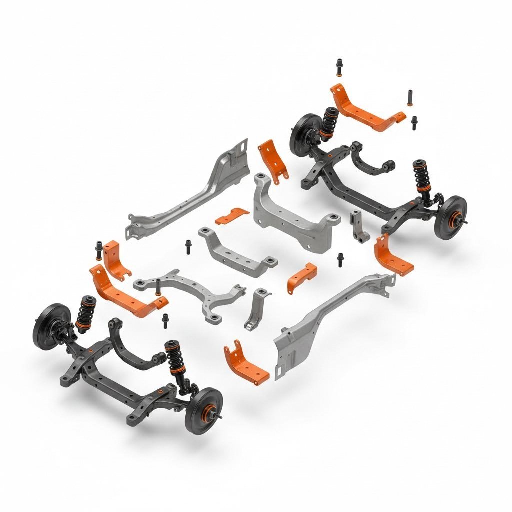
Walk through any automotive production facility and you'll see CNC metal forming machine operations running continuously. The industry's demand for lightweight yet structurally sound components makes formed metal parts indispensable. Think about what keeps a vehicle performing safely: chassis mounts, suspension brackets, underbody panels, and structural reinforcements all start as flat sheets before CNC processes shape them into precise three-dimensional forms.
What makes automotive applications particularly demanding? Tolerances. A bracket that's off by a millimeter can create vibration, accelerate wear, or compromise crash performance. According to industry specialists, vehicle manufacturing depends heavily on formed metal parts for things like chassis mounts, brackets, and underbody panels, where CNC forming makes it possible to repeat these parts at scale while holding performance-critical tolerances.
The range of automotive formed parts includes:
- Structural brackets: Engine mounts, transmission supports, and subframe attachments requiring precise geometry
- Suspension components: Control arm brackets, spring perches, and shock mounts handling dynamic loads
- Body structural elements: Reinforcement panels, door intrusion beams, and pillar stiffeners
- Underbody protection: Skid plates, heat shields, and splash guards formed for aerodynamic efficiency
- Interior structural supports: Dashboard frames, seat mounting brackets, and console structures
Manufacturers serving automotive OEMs face intense pressure to deliver quality parts quickly. Companies like Shaoyi (Ningbo) Metal Technology address this challenge through IATF 16949 certification—the automotive industry's quality management standard—ensuring that chassis, suspension, and structural components meet the rigorous requirements automakers demand. Their approach of bridging 5-day rapid prototyping with automated mass production reflects how modern CNC metal fabrication supports the industry's need for both speed and consistency.
Aerospace Structural Applications
If automotive tolerances seem tight, aerospace takes precision to another level entirely. When parts fly at 35,000 feet, failure isn't an inconvenience—it's catastrophic. CNC forming enables the production of structural components that balance extreme strength requirements with aggressive weight reduction targets.
According to Yijin Solution's aerospace fabrication specialists, sheet metal fabrication is crucial in aerospace where precise, lightweight parts are key. The process involves cutting, bending, and assembling metal structures used in aircraft, satellites, and spacecraft.
Aerospace applications demand materials that most industries never touch. Titanium alloys like Ti-6Al-4V, high-strength aluminum alloys including 7075, and specialized stainless steel grades form the backbone of aircraft structural components. These materials present unique forming challenges:
- Titanium alloys: Require elevated temperature forming (500-600°C) for complex geometries; excellent strength-to-weight ratio
- 7075 Aluminum: High strength but reduced ductility demands careful bend radius selection and often annealed tempers
- Inconel and specialty alloys: Extreme heat resistance for engine components; challenging springback characteristics
The figur sheet metal approach and similar advanced forming technologies are increasingly relevant for aerospace applications. Complex curvatures that once required expensive hydroforming dies can now be achieved through incremental forming or robotic methods. Wing skin panels, fuselage sections, and engine nacelle components benefit from these flexible manufacturing approaches.
Figur machine technology and digital forming methods prove particularly valuable for aerospace prototyping. When a new aircraft design requires evaluation of multiple structural configurations, the ability to produce test components without waiting months for dedicated tooling accelerates development cycles dramatically.
From Prototype to Production Volume
Here's where many manufacturers struggle: the transition from successful prototype to consistent production. You've proven your design works with a handful of parts, but scaling to hundreds or thousands introduces new challenges. Material lot variations, tooling wear, operator shifts, and equipment differences can all undermine the consistency you achieved during prototyping.
According to DeWys Manufacturing, transitioning from a prototype to full-scale production involves scaling up the fabrication process while maintaining precision and quality. Automation and advanced manufacturing technologies play a key role in this phase, allowing for the efficient and consistent production of metal parts.
The prototyping-to-production journey typically follows this progression:
- Concept validation: Initial prototypes prove design feasibility; tolerances may be relaxed during exploration
- Design refinement: DFM feedback from fabrication partners identifies improvements for manufacturability
- Process development: Tooling selection, bend sequences, and quality checkpoints get established
- Pilot production: Small batch run validates consistency and identifies process adjustments
- Scale-up: Volume production begins with documented procedures and statistical process control
- Continuous improvement: Ongoing optimization reduces cycle times and costs while maintaining quality
What separates manufacturers who navigate this transition successfully from those who struggle? Comprehensive DFM support before production begins. Identifying potential issues during design review prevents costly discoveries on the production floor.
General manufacturing sectors beyond automotive and aerospace also benefit from this structured approach. Electronics enclosures, HVAC components, industrial equipment housings, and architectural elements all move through similar prototype-to-production pathways. According to CNC forming specialists, applications extend to creating metal housings, brackets, and internal structures for electronics where tight tolerances ensure components fit cleanly and wires route properly.
For manufacturers evaluating production partners, the ability to support the complete journey matters. Quick prototyping turnaround proves meaningless if the same partner can't scale to your volume requirements. Look for fabricators offering rapid prototyping capabilities alongside production automation. Shaoyi's model of combining 5-day prototype turnaround with high-volume stamping and 12-hour quote response exemplifies this end-to-end capability, ensuring that your parts can evolve from initial concept through full production without switching suppliers mid-project.
The integration of quality systems throughout this journey proves equally critical. IATF 16949 certification for automotive applications, AS9100 for aerospace, and ISO 9001 for general manufacturing provide frameworks that ensure consistent quality as volumes scale. These certifications aren't just paperwork—they represent documented processes, statistical controls, and continuous improvement systems that maintain part quality regardless of production volume.
With a clear understanding of where CNC metal forming applies across industries and how parts move from concept to production, the final consideration becomes selecting the right approach and partner for your specific project requirements.
Choosing Your CNC Metal Forming Path Forward
You've explored the techniques, understood the materials, and seen real-world applications. Now comes the decision that actually impacts your bottom line: selecting the right CNC sheet metal forming approach and finding a manufacturing partner who can execute it. Get this wrong, and you're stuck with delays, quality issues, or costs that spiral beyond your budget. Get it right, and your production runs smoothly from first prototype to final delivery.
The criteria for making this decision aren't complicated—but they're often overlooked. Let's walk through a systematic evaluation process that helps you match your project requirements to the best cnc machine for metal work and the partner capable of running it effectively.
Matching Technology to Project Requirements
Before you start calling manufacturers, get clear on what your project actually demands. Different CNC sheet metal forming methods suit different situations, and mismatches waste everyone's time.
Ask yourself these foundational questions:
- What's your production volume? Single prototypes favor incremental forming or manual methods. Thousands of identical parts justify stamping dies. Mid-volume runs often work best with press brake operations.
- How complex is your geometry? Simple bends require less sophisticated equipment. Compound curves, deep draws, or tight-radius features demand specialized processes.
- What tolerances must you hold? Standard commercial tolerances of ±0.5 degrees differ dramatically from precision requirements of ±0.1 degrees. Tighter specs mean more capable equipment and higher costs.
- What's your timeline? Rapid prototyping needs differ from production scheduling. Some partners excel at quick-turn work; others optimize for sustained high-volume output.
Your answers shape which sheet metal press forming method applies and which manufacturers can realistically serve your needs. A shop specializing in architectural panels likely can't meet automotive chassis tolerances. A high-volume stamping operation probably won't prioritize your five-part prototype order.
Evaluating Manufacturing Partners
Finding a partner isn't just about equipment lists. According to Metal Works' manufacturing guidance, choosing the right partner means evaluating their ability to deliver rapid parts while avoiding costly delays—capabilities that directly impact your supply chain performance.
Follow this structured evaluation process:
- Verify relevant certifications: For automotive applications, IATF 16949 certification signals a quality management system specifically designed for automotive manufacturing. This certification proves the supplier limits defects while reducing waste and wasted effort. Aerospace work typically requires AS9100. General manufacturing benefits from ISO 9001 foundations.
- Assess DFM capabilities: Can the manufacturer review your designs and identify problems before production? According to Metal Works, expert teams providing Design for Manufacturability aid free of charge help finetune designs and avoid time-consuming errors down the line. This upfront investment prevents expensive rework later.
- Evaluate prototyping speed: How quickly can they produce sample parts? Some manufacturers offer 1-3 day rapid prototypes, allowing you to validate designs and move to production faster. Slow prototyping means weeks of waiting before you even know if your design works.
- Confirm production scalability: Can they handle your volume requirements? A one-stop manufacturing facility controlling every step of the process limits parts getting hung up with outside vendors. Ask about capacity, automation levels, and typical lead times for your projected quantities.
- Check on-time delivery track record: Request delivery performance metrics. Reliable partners track and report their on-time percentages—96% or higher annually indicates mature logistics and production planning.
- Review equipment capabilities: Does their machinery match your requirements? Advanced equipment enables laser cuts to 0.005 inch, bends accurate to 0.010 inch, and punched holes to 0.001 inch. Understand what precision their equipment actually delivers.
- Examine secondary service integration: Do they offer in-house finishing, coating, or assembly? Integrated services streamline your supply chain and reduce handoff delays between vendors.
From Quote to Quality Parts
The quoting process reveals a lot about a potential partner. Responsive manufacturers who understand your needs provide detailed quotes quickly, while disorganized operations take weeks and still miss critical details.
When requesting quotes, provide complete information:
- CAD files: 3D models and flat patterns in standard formats
- Material specifications: Exact alloy, temper, and thickness requirements
- Quantity requirements: Initial order size plus projected annual volumes
- Tolerance callouts: Critical dimensions and acceptable variations
- Surface finish requirements: Appearance standards and any coating needs
- Delivery timeline: When you need parts and how frequently
A manufacturer's quote turnaround time indicates their operational efficiency. Partners offering 12-hour quote response demonstrate the systems and expertise to evaluate projects quickly. Extended quote delays often predict production delays too.
The transition from prototype approval to production should feel seamless. Your partner should maintain the same quality standards, tolerances, and documentation across both phases. Statistical process control, first-article inspection reports, and ongoing quality monitoring ensure consistency as volumes scale.
For manufacturers seeking a partner that combines speed, quality, and comprehensive support, Shaoyi (Ningbo) Metal Technology offers a compelling combination of capabilities. Their 5-day rapid prototyping accelerates design validation, while automated mass production handles volume requirements efficiently. IATF 16949 certification ensures automotive-grade quality management, and comprehensive DFM support catches design issues before they become production problems. With 12-hour quote turnaround, you get answers quickly rather than waiting days to understand project feasibility and costs.
The path from raw sheet metal to precision formed components requires the right technology, the right materials, and the right manufacturing partner. Armed with the evaluation framework outlined here, you're equipped to make decisions that deliver quality parts on time and on budget—whether you're producing prototype brackets or production volumes of automotive chassis components.
Frequently Asked Questions About CNC Metal Forming
1. What is the CNC forming process?
CNC forming transforms flat sheet metal into three-dimensional parts by applying computer-controlled force through programmed toolpaths. The process uses press brakes, hydroforming equipment, or incremental forming tools to reshape metal without removing material. Critical parameters like bend depth, pressure, and sequence are digitally stored for precise repeatability, achieving tolerances as tight as ±0.1 degrees depending on the technique used.
2. What metals can you CNC form?
CNC forming works with aluminum alloys (5052, 6061, 7075), mild steel, stainless steel (304, 316), copper, and brass. Each material exhibits different springback characteristics—aluminum requires 2-5 degrees compensation while cold-rolled steel needs only 1-3 degrees. Material thickness typically ranges from 0.2mm to 25mm depending on the forming method, with grain direction significantly affecting bend quality and crack resistance.
3. How much does a Figur sheet metal forming machine cost?
The Figur G15 digital sheet forming machine costs approximately $500,000 USD as a turnkey solution including software and ceramic tools. This technology eliminates traditional die requirements by using software-driven toolpaths to shape metal directly from CAD files. While the initial investment is substantial, manufacturers report over 10x reduction in lead time and tooling cost savings exceeding $1 million per unique part design for low-to-medium volume production.
4. How much does custom sheet metal fabrication cost?
Custom sheet metal fabrication typically costs $4 to $48 per square foot depending on material selection, complexity, and customization requirements. CNC forming costs vary significantly by volume—single prototypes carry higher per-part costs due to programming setup, while production runs of 1000+ units dramatically reduce per-piece pricing. Tooling investments for stamping can exceed $100,000 but become economical when amortized across high volumes.
5. What is the difference between CNC and manual metal forming?
CNC forming delivers ±0.1° to ±0.5° precision with identical repeatability across thousands of parts, while manual methods achieve ±1° to ±2° depending on operator skill. CNC requires longer setup time for programming but offers lower per-part labor costs at volume. Manual forming excels for one-off prototypes, organic artistic shapes, and repair work where immediate adjustment flexibility outweighs automation benefits.