 Small batches, high standards. Our rapid prototyping service makes validation faster and easier —

CNC Machining Product Secrets: From Material Choice To Perfect Parts
What Makes CNC Machining Products Different From Traditional Manufacturing
A CNC machining product is any component manufactured through computer numerical control technology, where pre-programmed software dictates precise tool movements to shape raw materials into finished parts. Unlike conventionally manufactured items that rely on manual operator control, CNC machined components achieve tolerances as tight as 0.0002 to 0.0005 inches through automated, computer-controlled processes. This precision enables complex geometries that would be impossible or impractical with traditional hand-guided methods.
So what truly separates these precision cnc machined components from their manually produced counterparts? The answer lies in three critical factors: consistency, complexity, and repeatability. When you machine products using CNC technology, every single part matches the original CAD design specifications exactly. There's no variation from operator fatigue, no inconsistencies from human judgment calls, and no limitations on geometric complexity.
From Digital Blueprint to Physical Reality
Imagine this: you've designed the perfect component in CAD software. It looks flawless on screen with tight tolerances and clean geometry. But how does that digital file become a tangible, machined product?
The transformation follows a precise workflow. First, designers create a 3D model using software like SolidWorks, Fusion 360, or AutoCAD. This digital blueprint captures every dimension, curve, and specification. Next, skilled programmers translate that CAD model into G-code, the language CNC machines understand. This code tells the machine exactly how to move, cut, mill, or drill.
Once loaded into the CNC controller, the machine clamps your raw material and begins removing layers with computer-controlled precision. The cutting tools follow exact paths dictated by the program, progressively transforming stock material into your finished part. This CAD-to-product pipeline eliminates the guesswork inherent in manual methods, ensuring your cnc machining products match design intent perfectly.
Why Precision Manufacturing Changed Everything
Traditional machining relied entirely on the operator's skill and experience. Machinists manually adjusted tools, controlled feed rates, and made real-time judgments about cutting depth. While skilled craftspeople achieved impressive results, they faced unavoidable limitations.
CNC machining ensures precision that is difficult to achieve with manual machining. Every cut, shape, and detail is executed with exact accuracy, allowing the same product to be replicated flawlessly time and time again.
This shift from manual to automated production revolutionized what's possible. Consider these key differences:
- Precision: CNC machines follow pre-programmed instructions to the finest detail, eliminating errors from fatigue or miscalculations
- Complexity: Multi-axis CNC technology enables intricate features and geometries that manual methods simply cannot replicate
- Speed: Automated processes run continuously without breaks, dramatically increasing production efficiency
- Safety: Operators work at safe distances from moving parts, reducing workplace injury risks
For industries demanding zero-defect production, such as aerospace, medical devices, and automotive manufacturing, this transformation wasn't just convenient. It was essential. The ability to produce precision cnc machined components with exact repeatability opened doors to innovations that define modern technology. From smartphone housings to surgical instruments, CNC machined products form the backbone of manufacturing excellence.
Complete Taxonomy of CNC Machined Product Types
Understanding the different categories of CNC machined products helps you make smarter decisions about which manufacturing approach fits your project. Each product type stems from specific machining processes, and knowing these distinctions means you can communicate more effectively with suppliers and optimize your designs for manufacturability.
CNC components fall into four primary categories based on how they're produced: milled parts, turned parts, multi-axis complex geometries, and hybrid machined products. Let's break down each category so you can identify exactly where your parts belong.
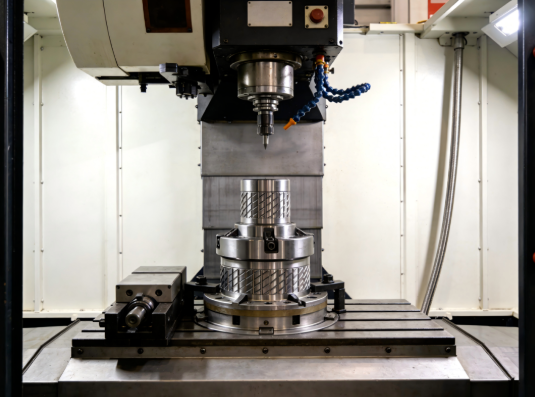
Milled Components and Their Defining Characteristics
CNC milling parts are created when a rotating cutting tool removes material from a stationary workpiece. This process excels at producing flat surfaces, pockets, slots, and intricate contours that define modern precision manufacturing.
What makes cnc milled parts distinctive? The cutting tool moves along multiple axes while spinning at high speeds, carving away material to create features like:
- Flat surfaces: Face milling creates smooth, level planes essential for mounting surfaces and interfaces
- Pockets and cavities: End milling hollows out material to create recessed areas for assemblies or weight reduction
- Slots and channels: Precise grooves guide components or allow fluid flow
- Complex contours: Profile milling traces intricate shapes for aesthetic or functional purposes
- Threads and holes: Drilling and tapping operations add fastening features
CNC milling components shine when your design requires prismatic shapes, meaning parts with predominantly flat surfaces and angular features. Think engine blocks, transmission housings, mounting brackets, and electronic enclosures. According to Unionfab's process comparison, milling handles a wide array of materials with varying hardness, including metals, plastics, and composites, making it incredibly versatile for diverse applications.
Common examples of cnc milling parts include:
- Aerospace structural components and airframe parts
- Medical device housings and surgical instrument bodies
- Automotive engine components and chassis assemblies
- Electronic enclosures and heat sinks
- Mold cavities and die components
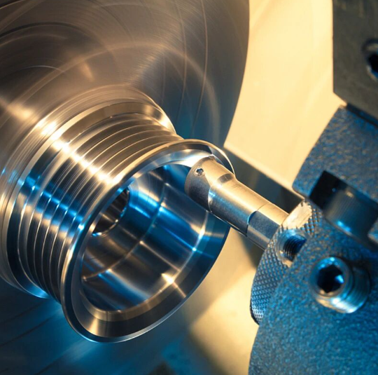
Turned Parts From Simple Shafts to Complex Assemblies
While milling rotates the tool, CNC turning flips the script. Here, the workpiece spins rapidly against a stationary cutting tool. This fundamental difference makes turned parts ideal for anything with rotational symmetry, including shafts, pins, bushings, and cylindrical housings.
The CNC lathe, or turning center, grips material in a chuck and spins it at high speeds. As the workpiece rotates, cutting tools approach from different angles to remove material and create precise diameters, tapers, and features. This process produces cnc mechanical parts with exceptional surface finishes and tight concentricity.
Turning operations create specific features that define this product category:
- Facing: Creates flat end surfaces perpendicular to the rotation axis
- External turning: Reduces diameter along the part's length
- Boring: Enlarges or refines internal hole dimensions
- Threading: Cuts precise screw threads for fastening
- Grooving: Creates recessed channels for O-rings or snap rings
- Knurling: Adds textured grip patterns to surfaces
Turned parts dominate applications requiring cylindrical or conical geometries. You'll find them everywhere, from automotive transmission shafts and hydraulic pistons to medical implant components and aerospace landing gear pins. The process excels at high-volume production because parts with rotational symmetry can be machined quickly and consistently.
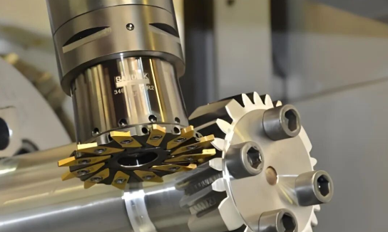
Multi-Axis Machined Products for Advanced Applications
Sounds complex? It is, but that complexity unlocks manufacturing possibilities that simpler machines simply cannot achieve. Multi-axis CNC machining, particularly 5-axis technology, adds rotational movement to the standard linear axes. This allows cutting tools to approach workpieces from virtually any angle.
Standard 3-axis machines move in X, Y, and Z directions. 5-axis CNC machining adds two rotational axes, typically A and B or B and C, enabling the production of complex machined parts in a single setup. This capability eliminates multiple fixturing operations, reduces errors from repositioning, and dramatically expands geometric possibilities.
What can multi-axis machining produce that simpler methods cannot?
- Turbine blades: Complex airfoil shapes with compound curves
- Impellers: Intricate vane geometries for pumps and compressors
- Medical prosthetics: Custom-fit implants matching patient anatomy
- Aerospace structural components: Weight-optimized parts with organic shapes
- Mold cores: Deep cavities with undercuts and complex surfaces
The trade-off? According to industry data, continuous 5-axis machining costs approximately twice as much as standard 3-axis milling due to machine complexity and programming requirements. However, for complex machined parts requiring tight tolerances and superior surface finishes, the investment often pays for itself through reduced setup time and improved quality.
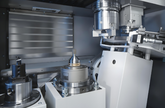
Hybrid Machined Products Combining Multiple Processes
Sometimes your part needs both turning and milling operations. That's where hybrid machining, specifically mill-turn centers, delivers exceptional value. These cnc machinery parts combine lathe and milling capabilities in a single machine, producing complex components without transferring between different setups.
Mill-turn centers mount workpieces on a rotating spindle like a lathe but also incorporate milling heads that can approach from multiple angles. This combination creates parts with both rotational features and prismatic elements, including off-center holes, flats, slots, and complex contours.
Typical hybrid machined products include:
- Crankshafts with both cylindrical journals and counterweight profiles
- Valve bodies requiring turned bores and milled port features
- Gear blanks with turned diameters and milled keyways
- Hydraulic manifolds combining drilled passages with milled mounting surfaces
| Product Category | Typical Applications | Complexity Level | Common Materials |
|---|---|---|---|
| CNC Milled Parts | Housings, brackets, enclosures, mold components | Low to High | Aluminum, steel, brass, plastics, composites |
| CNC Turned Parts | Shafts, pins, bushings, fittings, fasteners | Low to Medium | Steel, stainless steel, aluminum, brass, copper |
| Multi-Axis Complex Parts | Turbine blades, impellers, prosthetics, aerospace structures | High to Very High | Titanium, Inconel, aluminum, medical-grade metals |
| Hybrid Mill-Turn Parts | Crankshafts, valve bodies, gear blanks, manifolds | Medium to High | Steel, aluminum, stainless steel, specialty alloys |
Understanding this taxonomy helps you specify parts correctly and select suppliers with the right equipment for your needs. When you know whether your design calls for cnc milling components, turned features, or multi-axis capabilities, you can communicate requirements clearly and avoid costly misunderstandings during production.
Material Selection Guide for CNC Machined Products
Choosing the right material for your CNC machining product can make or break your project. The material you select directly impacts part performance, manufacturing cost, lead time, and long-term reliability. Yet many engineers and product designers struggle with this critical decision because guidance connecting materials to specific applications remains surprisingly scarce.
Here's the reality: there's no universal "best" material. The ideal choice depends entirely on your application requirements, including mechanical loads, operating environment, weight constraints, and budget. Let's walk through the major material categories so you can make informed decisions for your machined components.
Metal Selection for Structural and Precision Components
Metals dominate CNC machining for good reason. They offer exceptional strength, dimensional stability, and thermal resistance that most applications demand. But with dozens of alloys available, how do you narrow down your options?
Aluminum remains the workhorse of machined metal parts. According to Protolabs, aluminum is the most common metal on the planet, and its thin oxide layer makes it essentially corrosion-free in most environments. The 6061 alloy works beautifully for bicycle frames, SCUBA tanks, vehicle frames, and general-purpose parts. Need more strength? 7075 aluminum delivers properties ideal for molds, tooling, and aircraft frames.
Key properties of aluminum alloys include:
- Excellent machinability: Cuts quickly with minimal tool wear
- Lightweight: Approximately one-third the weight of steel
- Good thermal conductivity: Perfect for heat sinks and thermal management
- Corrosion resistance: Natural oxide layer protects against environmental exposure
- Cost-effective: Lower material and machining costs than most alternatives
Steel delivers when strength and hardness matter most. CNC steel parts span everything from structural components to precision gears. Carbon steels like 1018 and 1045 offer good machinability and can be heat-treated for increased hardness. For corrosive environments, stainless steel grades such as 303, 304, and 316 provide excellent resistance while maintaining structural integrity.
Titanium occupies the premium tier of metal cnc machined parts. With a melting point around 3,000 degrees Fahrenheit, titanium maintains its form under extreme heat while offering exceptional strength-to-weight ratios. However, this performance comes at a price. Titanium's high melting point makes processing difficult, and the material is notoriously challenging to machine, driving up costs significantly.
Titanium properties worth considering:
- Exceptional strength-to-weight ratio: Stronger than aluminum yet lighter than steel
- Superior corrosion resistance: Outperforms stainless steel in aggressive environments
- Low thermal expansion: Maintains dimensional stability under temperature variations
- Biocompatibility: Suitable for medical implants and devices
- Higher cost: Material and machining expenses exceed most alternatives
Engineering Plastics for Lightweight CNC Products
When you need lightweight components, chemical resistance, or electrical insulation, engineering plastics deliver capabilities metals simply cannot match. Modern CNC equipment machines plastics with the same precision as metals, opening doors to innovative designs.
PEEK (Polyetheretherketone) represents the high-performance end of engineering plastics. According to industry experts, PEEK offers exceptional strength, stiffness, and dimensional stability even in challenging environments requiring high temperature and chemical resistance. This material resists abrasion and wear, making it ideal for parts experiencing significant stress and friction. The trade-off? PEEK costs more than other plastics, so it's typically reserved for demanding applications.
Delrin (POM/Acetal) hits the sweet spot between performance and value. Known for excellent stiffness, low friction, and high wear resistance, Delrin produces machined components with tight tolerances and exceptional precision. Unlike nylon, Delrin resists moisture absorption, ensuring dimensional stability remains consistent over time. However, chemical compatibility requires careful evaluation since Delrin can be susceptible to attack in certain environments.
Nylon offers versatility at accessible price points. This plastic combines excellent strength with durability and low friction properties. Nylon machines easily to tight tolerances, making it suitable for intricate parts with complex geometries. One consideration: nylon absorbs moisture, which can affect dimensional stability and performance over extended periods.
Additional engineering plastics for CNC applications include:
- ABS: Good impact resistance and dimensional stability; easy to machine and finish
- Acrylic (PMMA): Optical clarity with good impact resistance; ideal for transparent components
- HDPE/PTFE: Excellent chemical resistance and low friction coefficients
- Garolite (G-10/FR4): Composite material offering high strength with electrical insulation
Material Properties That Drive Product Performance
Understanding key material properties helps you match specifications to application requirements. Here's what matters most when selecting materials for metal machined parts or plastic components:
Hardness determines wear resistance and durability. Harder materials resist scratching and deformation but typically require more aggressive cutting parameters and cause faster tool wear. For sliding contact applications, balance hardness against friction requirements.
Thermal conductivity matters for components managing heat. Aluminum's excellent heat transfer makes it ideal for heat sinks and thermal management applications. Plastics generally insulate, which benefits electrical components but limits thermal dissipation.
Machinability directly impacts production cost and lead time. Free-machining materials like 6061 aluminum and 303 stainless steel cut quickly with minimal tool wear. Difficult-to-machine materials such as titanium and hardened steels require specialized tooling, slower speeds, and more machine time.
Corrosion resistance determines environmental suitability. Marine, medical, and chemical processing applications demand materials that withstand aggressive environments. Stainless steels, titanium, and many plastics excel here, while carbon steels require protective coatings.
| Material Type | Best Applications | Machinability Rating | Cost Considerations |
|---|---|---|---|
| Aluminum (6061/7075) | Aerospace structures, heat sinks, enclosures, automotive brackets | Excellent | Low to moderate material cost; fast machining reduces labor |
| Steel (1018/1045) | Structural components, shafts, gears, fixtures | Good | Low material cost; moderate machining time |
| Stainless Steel (303/304/316) | Medical devices, food processing, marine, chemical equipment | Moderate | Moderate material cost; slower cutting speeds |
| Titanium (Ti 6Al-4V) | Aerospace, medical implants, high-performance motorsports | Difficult | High material and machining costs; specialized tooling required |
| PEEK | Medical devices, aerospace, semiconductor, high-temperature environments | Good | High material cost; machines similarly to metals |
| Delrin (POM) | Gears, bushings, bearings, precision mechanical parts | Excellent | Moderate material cost; fast machining |
| Nylon | Wear pads, rollers, insulators, lightweight structural parts | Excellent | Low material cost; consider moisture absorption |
| ABS | Prototypes, enclosures, consumer products, automotive trim | Excellent | Low cost; watch for warping on complex geometries |
When you're specifying materials for your next project, start with the end-use requirements and work backward. What loads will the part experience? What environment will it operate in? Does weight matter? What's your budget? Answering these questions narrows your options quickly and points toward materials that balance performance with practicality.
With materials selected, the next critical step involves tailoring your designs for specific industry requirements. Different sectors demand vastly different specifications, tolerances, and certifications that shape every aspect of the manufacturing process.
Industry Applications and Product Requirements Across Sectors
Every industry has its own definition of "good enough." For consumer products, minor dimensional variations might go unnoticed. But when you're machining cnc parts for a jet engine or a pacemaker, "good enough" means flawless execution every single time. The stakes couldn't be higher.
Different sectors demand vastly different specifications from their cnc machining parts. Tolerances that satisfy one industry might cause catastrophic failures in another. Understanding these sector-specific requirements helps you communicate effectively with manufacturers and ensure your components meet the standards that matter for your application.
Automotive Components Demanding Zero-Defect Production
Imagine a transmission gear failing at highway speeds. Or brake components that don't quite fit together properly. The automotive industry lives with this reality: every cnc machined automotive component must perform perfectly because lives depend on it.
Automotive manufacturers operate under relentless pressure to produce high volumes while maintaining exceptional quality. This balance drives specific requirements that shape how precision cnc machined parts are designed and manufactured.
Typical tolerance requirements for automotive applications include:
- Engine components: ±0.001" to ±0.0005" for pistons, cylinder heads, and valve train parts
- Transmission parts: ±0.0005" or tighter for gear shafts and synchronizer assemblies
- Chassis assemblies: ±0.005" to ±0.002" for suspension components and structural brackets
- Brake system components: ±0.001" for master cylinders, calipers, and ABS housings
- Fuel injection parts: ±0.0002" for precision nozzles and injector bodies
What sets automotive apart from other sectors? Volume expectations. While aerospace might order hundreds of parts, automotive programs often require tens of thousands of identical cnc precision machined components. This volume demands Statistical Process Control (SPC) monitoring throughout production runs to catch variations before they become defects.
IATF 16949 certification serves as the automotive industry's quality benchmark. This standard builds on ISO 9001 requirements while adding automotive-specific provisions for defect prevention, variation reduction, and continuous improvement. Suppliers without this certification typically cannot bid on major automotive programs.
Common automotive CNC machining parts include:
- Engine blocks and cylinder heads
- Transmission housings and gear components
- Turbocharger housings and impellers
- Suspension knuckles and control arms
- Electric vehicle motor housings and battery enclosures
- Steering system components
Aerospace Products Meeting AS9100 Standards
When a component fails at 35,000 feet, there's no pulling over to the side of the road. Aerospace manufacturing represents perhaps the most demanding application for CNC machining products, where tolerances measured in microns can mean the difference between safe flight and catastrophic failure.
AS9100 certification defines the quality management framework for aerospace manufacturing. This standard incorporates ISO 9001 requirements while adding rigorous provisions for configuration management, risk assessment, and product traceability. According to Modus Advanced, aerospace manufacturing demands tight tolerance CNC machining services that deliver components capable of withstanding extreme conditions while maintaining dimensional stability.
What makes aerospace tolerance requirements so demanding? Consider this: engine components operate in temperature ranges exceeding 1000°C (1832°F) while requiring tolerances measured in microns to maximize efficiency and prevent failure. Control surfaces, structural elements, and landing gear components must maintain precise dimensional relationships under enormous loads and environmental stresses.
Critical aerospace product categories include:
- Structural components: Wing spars, fuselage frames, and bulkheads requiring ±0.0005" or tighter
- Engine parts: Turbine blades, compressor discs, and combustion chambers with tolerances to ±0.0001"
- Flight control surfaces: Flap mechanisms, actuator housings, and control linkages
- Landing gear components: Struts, actuators, and brake assemblies
- Avionics housings: Enclosures for navigation, communication, and flight management systems
Material traceability presents another aerospace-specific requirement. Every piece of raw material must be traceable to its original mill certification. Heat lot numbers, material certifications, and processing records follow components throughout their entire lifecycle. This documentation enables investigators to trace any failure back to its root cause.
Medical Device Components Under FDA Scrutiny
Now imagine a surgical implant that triggers an immune response, or an instrument that doesn't fit precisely during a critical procedure. Medical device manufacturing combines the precision demands of aerospace with unique biocompatibility and regulatory requirements.
According to AIP Precision Machining, medical device manufacturing represents the most demanding application for tight tolerance CNC machining services, where dimensional accuracy directly impacts patient safety and treatment effectiveness. Implantable devices require biocompatible surface finishes and dimensional precision that ensures proper fit and function within the human body, with tolerances often measuring in microns.
FDA compliance shapes every aspect of medical device production. The regulatory framework classifies devices into three risk-based categories:
- Class I devices: Low risk items like bandages and examination gloves requiring basic controls
- Class II devices: Moderate risk devices such as surgical instruments requiring 510(k) clearance
- Class III devices: High risk implants and life-sustaining equipment requiring Premarket Approval (PMA)
ISO 10993 testing protocols evaluate biocompatibility through cytotoxicity screening, sensitization testing, and implantation studies. These tests ensure materials won't trigger adverse reactions when in contact with human tissue. For implantable components, manufacturers must demonstrate non-toxicity, non-carcinogenicity, and non-irritation to biological tissues.
Typical medical device CNC products include:
- Orthopedic implants: knee, hip, and spinal components
- Surgical instruments: scalpel handles, forceps, and retractors
- Dental implants and prosthetic components
- Diagnostic equipment housings and assemblies
- Drug delivery device components
- Cardiovascular stents and catheter components
CNC machining can achieve tolerances as tight as ±0.001" for critical medical components, though material-specific factors affect achievable precision. PEEK components maintain tolerances of ±0.001", while nylon requires more generous allowances at ±0.002" due to its moisture absorption characteristics.
| Requirement Dimension | Automotive | Aerospace | Medical Devices |
|---|---|---|---|
| Typical Tolerances | ±0.001" to ±0.0005" | ±0.0005" to ±0.0001" | ±0.001" to ±0.0001" |
| Primary Certification | IATF 16949 | AS9100D | ISO 13485, FDA registration |
| Volume Expectations | High (10,000+ units typical) | Low to Medium (100-5,000 units) | Low to Medium (varies by device class) |
| Traceability Requirements | Lot-level tracking | Serial number tracking per component | Full material and process traceability |
| Quality Control Focus | Statistical Process Control (SPC) | First Article Inspection, 100% critical feature inspection | Biocompatibility testing, sterilization validation |
| Documentation Depth | PPAP packages, control plans | Full manufacturing records, material certs | Design history files, risk management files |
| Surface Finish Requirements | Application-dependent (Ra 32-125 μin typical) | Stringent (Ra 16-63 μin typical) | Very stringent (Ra 8-32 μin for implants) |
Understanding these industry-specific requirements positions you to communicate effectively with CNC machining partners. Whether you're developing automotive transmission components, aerospace structural parts, or medical implants, knowing the applicable tolerances, certifications, and documentation requirements streamlines your path from design to production.
But meeting industry specifications starts long before machining begins. The design decisions you make during product development fundamentally shape manufacturing outcomes, costs, and quality. That's where Design for Manufacturability principles come into play.
Design for Manufacturability Principles in CNC Product Development
Here's a scenario that plays out in machine shops every day: an engineer submits a beautifully detailed CAD model, only to receive a quote three times higher than expected. The culprit? Design choices that look perfect on screen but create manufacturing nightmares. Every cnc machining part carries the DNA of its design decisions, and those decisions ripple through production cost, lead time, and final quality.
Design for Manufacturability (DFM) bridges the gap between what you want and what's practical to produce. According to Modus Advanced, effective DFM implementation can reduce manufacturing costs by 15-40% and cut lead times by 25-60% compared to non-optimized designs. Those aren't minor savings. They're game-changers for competitive product development.
A seemingly minor design decision—like specifying an unnecessary fillet or choosing an overly tight tolerance—can transform a straightforward CNC machining operation into a complex, time-intensive process that delays product launch by weeks.
Tolerance Specifications That Balance Precision and Cost
When you specify tolerances on your machined part, you're essentially telling the manufacturer how much time and care to invest. Tighter tolerances demand slower cutting speeds, more precise equipment, temperature-controlled environments, and extensive inspection. The relationship between cost and tolerance isn't linear—it's exponential.
Consider this breakdown of how tolerance specifications affect your cnc machine part production:
- ±0.005" (±0.13mm): Standard operations with baseline lead times and costs
- ±0.002" (±0.05mm): Increased precision requirements adding 25-50% to lead time
- ±0.0005" (±0.013mm): Specialized equipment and controlled environments adding 100-200%
- ±0.0002" (±0.005mm): Temperature control, stress relief operations, and specialized inspection adding 300% or more
The trap many engineers fall into? Applying blanket tolerances across entire parts. As one engineering manager notes, one of the most common cost drivers is unnecessarily tight tolerances applied globally when only one or two features are truly critical. A medical startup recently reduced their aluminum housing cost from $300 to $85 per unit—a 70% reduction—simply by relaxing tolerances on non-critical features while maintaining precision only where function demanded it.
Ask yourself: which features actually require tight tolerances for proper function? Mating surfaces, bearing fits, and assembly interfaces typically need precision. Cosmetic surfaces and non-functional geometry rarely do. This intentional approach tells your manufacturing partner exactly where to focus efforts.
Feature Design Rules for Optimal Machinability
Understanding how the parts of cnc machine tools interact with your design unlocks significant cost savings. CNC cutting tools are round, which means they physically cannot create certain geometries without extraordinary measures.
Internal corner radii represent one of the most common DFM issues. A 90-degree internal corner looks clean in CAD, but a round end mill simply cannot produce it. Achieving sharp corners requires moving your part to Electrical Discharge Machining (EDM), which can cost 3 to 5 times more per corner than standard milling.
Here are the recommended internal corner radii specifications:
- Standard internal corners: Minimum 0.005" (0.13mm), recommended 0.030" (0.76mm)
- Deep pockets: Minimum 0.010" (0.25mm), recommended 0.060" (1.52mm)
- Thin wall features: Minimum 0.020" (0.51mm), recommended 0.080" (2.03mm)
Wall thickness directly impacts machining success. Thin walls flex and vibrate during cutting, forcing machinists to slow down dramatically. For walls thinner than 0.5mm, this careful approach can increase machining time by 100% to 300%. Keep metal wall thicknesses above 0.8mm and plastic walls above 1.5mm to avoid deformation risks.
Deep pockets and holes create tool access challenges. Standard drill bits perform well up to aspect ratios of 4:1 (depth to diameter). Beyond that threshold, specialized tooling and peck drilling cycles become necessary, adding significant cost and time. Limit pocket depths to no more than 6x the smallest internal corner radii.
The parts of cnc machines also determine what's practical for your design. Features requiring 5-axis machining cost 300-600% more than equivalent 3-axis operations. Whenever possible, align features with X, Y, and Z planes to enable simpler machining approaches.
From CAD Model to Production-Ready Design
Your CAD model must eventually translate into G-code that guides machine movements. Understanding this workflow helps you create designs that machine efficiently rather than fighting the process.
Complex curves and varying radii significantly increase programming time. While your CAD software renders them beautifully, each unique radius requires separate tool path calculations. Using consistent radii throughout your design simplifies programming and reduces machining time.
Common DFM mistakes and their solutions:
- Sharp internal corners: Add minimum 0.030" radius to all internal corners for standard tooling compatibility
- Knife edges: Add 0.005-0.015" outside fillets to prevent fragile edges and deburring requirements
- Complex decorative curves: Eliminate non-functional geometry; use consistent radii where curves are necessary
- Cast-optimized prototype designs: Create separate machining-optimized versions eliminating draft angles
- Blanket tight tolerances: Apply precision only to critical mating surfaces and functional features
- Specifying drill sizes for threads: Call out thread class instead, allowing manufacturers to optimize processes
- Inaccessible features: Design features reachable by standard probes to simplify inspection
Surface finish specifications deserve careful attention too. Standard machined finishes of Ra 63-125 μin satisfy most applications. Demanding smoother finishes requires additional operations that extend lead time by 25-100% and increase costs proportionally. Before specifying a polished finish, ask whether it serves a functional purpose or simply adds expense.
One critical consideration often overlooked: documentation clarity. Establish clear precedence between CAD models and engineering drawings to eliminate ambiguity. When drawings and models conflict, manufacturers waste time seeking clarification—time that extends your lead time and frustration.
The investment in DFM thinking pays dividends throughout production. By understanding how your design decisions affect the machining process, you create parts that are not only brilliant in concept but achievable in reality. This knowledge positions you to communicate effectively with manufacturers and ensure your CNC machining products arrive on time, on budget, and exactly as intended.
Quality Control Standards and Inspection Methods for CNC Products
You've designed the perfect part, selected ideal materials, and optimized for manufacturability. But how do you know the finished cnc machined parts actually match your specifications? Quality control bridges the gap between design intent and physical reality, transforming confidence from hope into certainty.
According to FROG3D, without proper quality control, defective parts can result in significant financial losses and a negative industry reputation. The stakes are real: a single out-of-tolerance component can cascade into assembly failures, warranty claims, or worse. Understanding how cnc machining capabilities are verified helps you evaluate suppliers and ensure your machined parts needed for critical applications meet every requirement.
Dimensional Inspection Methods and Equipment
Think of dimensional inspection as your quality insurance policy. Different measurement technologies suit different applications, and knowing which tool fits your needs helps you specify appropriate verification methods.
Coordinate Measuring Machines (CMM) represent the gold standard for complex geometry verification. These sophisticated instruments use tactile probes or non-contact sensors to capture precise 3D measurements, enabling thorough geometric verification against CAD models. CMMs excel at measuring complex machining components with tight tolerances and intricate features.
What makes CMM technology so valuable? The ability to measure virtually any accessible feature on your part with exceptional precision. Modern CMMs achieve measurement accuracy of 0.02mm (20 microns) with resolution up to 0.01mm, according to industry specifications. This precision proves essential for aerospace, medical, and automotive applications where microns matter.
Optical comparators project magnified silhouettes of parts onto screens where operators compare profiles against overlay charts. This method works beautifully for 2D profile verification, thread inspection, and edge quality assessment. While less sophisticated than CMMs, optical comparators provide fast, cost-effective verification for simpler geometries.
Surface finish measurement quantifies texture quality using profilometers that trace across machined surfaces. These instruments measure surface roughness in microinches (Ra values), ensuring finishes meet specifications for function and appearance. Surface condition affects everything from bearing performance to paint adhesion.
Additional inspection tools supporting cnc capabilities verification include:
- Micrometers and calipers: Handheld precision instruments for quick dimensional checks
- Gauge blocks: Reference standards for calibrating other measuring equipment
- Bore gauges: Specialized tools for internal diameter measurement
- Thread gauges: Go/no-go verification for threaded features
| Inspection Method | Best Applications | Precision Level | Speed |
|---|---|---|---|
| Coordinate Measuring Machine (CMM) | Complex 3D geometries, GD&T verification, first article inspection | ±0.0008" (0.02mm) | Moderate |
| Optical Comparator | 2D profiles, thread forms, edge inspection | ±0.001" (0.025mm) | Fast |
| Surface Profilometer | Surface roughness, texture analysis | Ra 0.1 μin resolution | Fast |
| Digital Micrometers | External dimensions, thickness, diameter | ±0.0001" (0.0025mm) | Very Fast |
| Non-Destructive Testing (NDT) | Internal flaws, material integrity, weld inspection | Defect detection only | Moderate |
Industry Certifications That Guarantee Product Quality
When evaluating CNC machining suppliers, certifications tell you more than marketing claims ever could. These third-party validations confirm that quality management systems meet rigorous, independently audited standards.
ISO 9001 serves as the foundation for quality management worldwide. According to CNC Machines, ISO 9001 is the most recognized quality management system standard globally, focusing on meeting customer needs and enhancing satisfaction through effective system processes. This certification applies across virtually all industries and establishes baseline quality management expectations.
What ISO 9001 certification guarantees:
- Documented quality management processes and procedures
- Regular internal audits and management reviews
- Customer focus embedded in operations
- Continuous improvement commitments
- Corrective action procedures for addressing nonconformances
AS9100 builds on ISO 9001 with aerospace-specific requirements. This certification proves essential for suppliers serving the aviation, space, and defense sectors where product failure carries catastrophic consequences. AS9100-certified manufacturers demonstrate enhanced configuration management, risk assessment protocols, and complete product traceability.
What AS9100 certification adds beyond ISO 9001:
- First article inspection requirements
- Configuration management and change control
- Risk management throughout production
- Prevention of counterfeit parts
- Enhanced traceability from raw material to delivery
IATF 16949 addresses the automotive sector's unique demands for zero-defect production at scale. This certification combines ISO 9001 fundamentals with automotive-specific provisions for defect prevention, variation reduction, and supply chain management. Suppliers without IATF 16949 certification typically cannot bid on major automotive programs.
What IATF 16949 certification ensures:
- Advanced product quality planning (APQP) processes
- Production Part Approval Process (PPAP) capability
- Statistical process control implementation
- Failure mode and effects analysis (FMEA)
- Measurement system analysis requirements
Statistical Process Control for Consistent Production
Here's a reality that catches many buyers off guard: a perfect first article inspection doesn't guarantee the 500th part will match specifications. Tools wear, temperatures fluctuate, and materials vary. Statistical Process Control (SPC) catches these drift patterns before they produce defective parts.
According to CNCFirst, one successful part does not guarantee the next will be good. That's why FAI alone is not enough—you also need SPC to continuously monitor the process. This monitoring system uses statistical methods to detect and correct deviations early, preventing defective parts from being produced.
Imagine the difference between these two approaches:
Traditional sampling inspection: An operator produces 100 parts, then quality inspects 10 randomly. If 3 are out of tolerance, the problem has already occurred. The other 90 parts might hide defects too, leading to rework or scrap.
SPC monitoring: Key dimensions are checked at regular intervals—perhaps the 5th, 10th, and 20th piece—and plotted on control charts in real time. If a dimension begins drifting toward the tolerance limit, action is taken immediately before the problem grows.
Control charts serve as early warning systems. They distinguish normal process variation from genuine signals requiring intervention. When data points approach control limits, operators adjust tool compensation, replace cutting edges, or address environmental factors before producing out-of-tolerance parts.
A real-world example illustrates SPC's value: a medical device customer's previous supplier achieved 92% yield. By implementing SPC, the new supplier discovered that starting at the 85th part, a critical bore diameter slowly drifted upward during tool life. They replaced cutting edges at the 80th piece and adjusted offsets. The result? 99.7% yield, saving approximately $1,500 per batch in rework and scrap costs.
SPC monitors sources of machining errors including:
- Tool wear progression throughout production runs
- Thermal expansion affecting dimensional stability
- Material hardness variations between lots
- Machine calibration drift over time
- Environmental temperature and humidity changes
For buyers, SPC capability signals manufacturing maturity. Suppliers who integrate statistical monitoring deliver consistent results across production runs, reducing your risk of receiving batches with hidden quality issues. When evaluating potential partners, ask about their SPC implementation and how they use data to maintain process stability.
Quality control isn't just about catching problems—it's about preventing them. The combination of precise inspection equipment, recognized certifications, and statistical monitoring creates a quality assurance framework that protects your investment and ensures every CNC machining product meets your specifications.
How to Specify and Order CNC Machined Products Successfully
You've nailed the design, selected the perfect material, and understand what quality looks like. Now comes the moment of truth: actually ordering your cnc machining components. This step trips up even experienced engineers because the gap between having a great design and receiving great parts depends entirely on how well you communicate requirements and evaluate potential partners.
Think about it from the manufacturer's perspective. They receive dozens of quote requests daily, ranging from napkin sketches to fully documented engineering packages. The clarity of your submission directly impacts quote accuracy, lead time estimates, and ultimately the quality of parts you receive. Let's walk through the complete ordering process so you can navigate it confidently.
Preparing Technical Documentation for Quotes
Your quote package tells manufacturers everything they need to know—or leaves them guessing. Incomplete documentation leads to inaccurate quotes, unexpected costs, and frustrating back-and-forth communications that delay your project.
According to Protolabs, tolerancing goes beyond simple length and width specifications to include surface roughness, geometric relationships, and positional accuracy. Your documentation must capture all these requirements clearly to receive accurate quotes.
Here's what a complete technical package includes:
- 3D CAD model: Provide native files (STEP, IGES, or Parasolid formats) that manufacturers can import directly into CAM software. Ensure your model represents the final, production-ready geometry without construction artifacts or suppressed features.
- 2D engineering drawing: Include dimensioned drawings with critical tolerances called out explicitly. Establish clear precedence between CAD models and drawings to eliminate ambiguity when conflicts arise.
- Material specification: Call out specific alloy grades (6061-T6 aluminum, not just "aluminum") and any heat treatment or hardness requirements. Include acceptable alternatives if flexibility exists.
- Tolerance requirements: Specify tolerances for critical features using bilateral notation (+0.000/-0.010 in.) or limit-based tolerances (1.005/0.995 in.). Stick with three-decimal-place dimensions unless precision demands otherwise.
- Surface finish requirements: Define Ra values for critical surfaces. Standard finishes of 63 µin. for flat surfaces and 125 µin. for curved surfaces satisfy most applications without premium costs.
- GD&T callouts: For complex parts requiring feature relationships, include geometric dimensioning and tolerancing symbols for true position, flatness, cylindricity, concentricity, and perpendicularity as needed.
- Quantity and delivery requirements: State both initial quantities and anticipated annual volumes. Include target delivery dates and any flexibility that exists.
One critical consideration: manufacturers using cnc part machine technology need complete information upfront. Missing details force them to make assumptions—assumptions that might not match your expectations. When in doubt, over-document rather than under-document.
Evaluating Supplier Capabilities and Certifications
Not all cnc machining parts manufacturers are created equal. A supplier perfect for prototypes might struggle with production volumes. A shop excelling at aluminum might lack experience with titanium. Your evaluation framework should match potential partners to your specific requirements.
According to industry guidance, one of the primary factors to consider when sourcing CNC machining parts is the supplier's capability. Verify the supplier's machinery, materials, and production processes before placing orders to prevent delays and errors during manufacturing.
Key capabilities to evaluate include:
- Equipment inventory: Do they have the right cnc machines parts for your geometry? 3-axis mills handle most work, but complex parts require 5-axis capability. Turned parts need CNC lathes or mill-turn centers.
- Material experience: Ask about their familiarity with your specified material. Machining titanium differs dramatically from aluminum, and experience matters.
- Tolerance capability: Verify they can hold your required tolerances consistently, not just occasionally. Ask about their typical tolerance ranges and inspection equipment.
- Quality certifications: Match certifications to your industry. ISO 9001 provides baseline assurance. Aerospace needs AS9100. Automotive demands IATF 16949. Medical requires ISO 13485.
- Inspection capabilities: Confirm they have appropriate measurement equipment. CMM capability proves essential for complex geometries and GD&T verification.
- Production capacity: Ensure they can scale from prototype quantities to production volumes without bottlenecks. Ask about typical lead times for different order sizes.
- Communication responsiveness: Evaluate how quickly and thoroughly they respond during the quote process. This responsiveness typically continues through production.
Request sample parts when possible. Examining actual work reveals more about quality standards than any certification or capability list. Look for clean deburring, consistent surface finishes, and dimensional accuracy.
From Rapid Prototyping to Scaled Production
Your project likely won't jump straight from concept to full production. According to UPTIVE Advanced Manufacturing, prototyping is the critical testing phase where ideas are shaped, refined, and validated for manufacturing and market success. Understanding this pathway helps you plan timelines and budgets realistically.
The prototype-to-production journey typically follows these phases:
Concept prototypes validate basic form and fit. Speed matters more than finish quality. Simple low-cost prototypes may cost between $100 and $1,000, according to industry estimates. These parts for cnc machine verification help you catch major design issues before investing in refined versions.
Functional prototypes test real-world performance. Materials and tolerances match production intent. Costs typically range from $1,000 to $10,000 depending on complexity. This phase reveals whether your design works as expected under actual operating conditions.
Pre-production runs bridge prototyping and full-scale manufacturing. According to UPTIVE, manufacturing at low volume is a critical step to bridging the gap between prototyping and full-scale production. It helps catch design, manufacturing, or quality issues, validate manufacturing processes, identify bottlenecks, and assess suppliers in terms of quality, responsiveness, and lead times.
Production scaling requires process optimization for efficiency and consistency. Large part cnc machining operations demand different considerations than prototype quantities, including fixture design, tool path optimization, and quality monitoring systems.
| Requirement | Prototype Phase | Production Phase |
|---|---|---|
| Primary Goal | Validate design and function | Consistent, cost-effective output |
| Typical Quantities | 1-50 pieces | 100-10,000+ pieces |
| Lead Time Priority | Speed (days to 2 weeks) | Reliability and scheduling |
| Cost Focus | Acceptable premium for speed | Per-unit cost optimization |
| Tooling Investment | Minimal (standard tooling) | Custom fixtures and dedicated tooling |
| Quality Approach | 100% inspection typical | SPC with sampling plans |
| Documentation | Basic inspection reports | Full PPAP packages, control plans |
| Design Changes | Expected and accommodated | Formal change control required |
| Supplier Relationship | Transactional | Partnership with ongoing communication |
One insight that saves both time and money: choose your production partner during prototyping when possible. Suppliers who manufacture your prototypes understand your design intent and can transition smoothly to production. Switching suppliers between phases forces new learning curves and risks introducing variation.
When comparing potential partners, look beyond per-piece pricing. According to industry experts, compare the cost structures of potential partners—some may offer lower per-unit costs for large production runs, while others excel at small-batch production. Understanding pricing, payment terms, and potential discounts helps you find the best deal for your specific volume requirements.
Effective communication throughout the process prevents most problems. Reliable CNC machining partners respond promptly, address concerns proactively, and ensure both parties understand requirements upfront. This transparency prevents misunderstandings that otherwise delay projects and inflate costs.
With your ordering process streamlined and supplier relationships established, you're positioned to receive high-quality cnc machining components consistently. But before committing to CNC machining for every project, it's worth understanding when alternative manufacturing methods might serve you better—a comparison that could save significant time and money on future projects.
CNC Machining Versus Alternative Manufacturing Methods
So you've got a part to manufacture. But is CNC machining actually the right choice? This question stumps many engineers and product managers because the answer depends entirely on your specific requirements. What can a cnc machine do better than alternatives—and when should you consider different approaches?
Here's the reality most manufacturing guides avoid: no single process wins every time. CNC machining excels in specific scenarios while 3D printing, injection molding, and casting each claim their own territories. Understanding these boundaries helps you make smarter decisions that optimize cost, quality, and timeline simultaneously.
Let's break down each comparison so you can confidently match your project requirements to the ideal manufacturing method.
CNC Machining Versus 3D Printing for Production Parts
The CNC versus 3D printing debate generates endless discussion, but the decision often comes down to three factors: volume, precision, and material requirements.
Precision and tolerances represent CNC machining's clearest advantage. According to Trustbridge, CNC machines achieve tolerances as tight as ±0.025mm, significantly tighter than most 3D printing methods. When your cnc machine products demand exact dimensional accuracy for mating surfaces or critical fits, CNC remains the superior choice.
What about 3D printing's strengths? The technology shines when geometric complexity reaches levels that would require extensive setups or prove impossible with subtractive methods. Internal channels, organic shapes, and lattice structures that reduce weight while maintaining strength—these examples of cnc limitations become 3D printing opportunities.
Consider these volume economics:
- 1-20 parts: 3D printing typically costs less due to zero tooling and minimal setup
- 20-5,000 parts: CNC machining becomes more economical as setup costs spread across larger quantities
- 5,000+ parts: Other methods like injection molding often overtake both processes
Material options create another distinction. CNC machining handles virtually any machinable material—metals, plastics, composites, and exotic alloys. According to Production-to-Go, material restrictions are unheard of in subtractive manufacturing, whether you need high-strength alloys, metal matrix composites, superalloys, or reflective metals.
3D printing, while expanding rapidly, still faces material limitations. Metal 3D printing struggles with reflective materials like copper and bronze. And here's a critical consideration: most 3D printed parts exhibit anisotropic properties, meaning strength varies depending on force direction relative to build layers. CNC machined parts from solid stock maintain consistent properties throughout.
Cnc machine examples where machining wins over printing include:
- High-precision bearing housings requiring ±0.001" tolerances
- Structural components needing isotropic material properties
- Parts requiring specific alloys not available in powder form
- Components demanding superior surface finishes without post-processing
When Casting or Injection Molding Makes More Sense
Imagine you need 50,000 identical aluminum housings or 100,000 plastic enclosures. CNC machining each one individually would be absurdly expensive. This is where casting and injection molding dominate—but only above certain volume thresholds.
Injection molding delivers unmatched economics for high-volume plastic parts. According to Trustbridge, once tooling is created, injection molding produces millions of parts with very low unit cost and exceptional repeatability. The catch? Mold costs ranging from thousands to hundreds of thousands of dollars, plus lead times of weeks or months for tooling.
The break-even calculation matters enormously. Industry data suggests injection molding becomes cost-effective around 5,000 to 10,000 units, though this varies significantly based on part complexity and material choice. Below this threshold, CNC machining often proves more economical despite higher per-piece costs.
What can i make with a cnc machine that injection molding handles better at scale? Consider these machining examples where molding wins:
- Consumer product housings produced in tens of thousands
- Automotive interior components with consistent cosmetic requirements
- Medical device enclosures requiring FDA-validated processes
- Electronic housings with snap-fit features and thin walls
Metal casting serves similar high-volume metal applications. Investment casting, die casting, and sand casting each offer advantages for specific geometries and volumes. Complex internal passages that would require extensive CNC operations become straightforward with casting—though surface finish and tolerances typically require secondary machining operations.
Geometry considerations also influence the decision. Injection molding requires draft angles for part ejection—typically 1-2 degrees on vertical surfaces. CNC machining imposes no such restriction. If your design cannot accommodate draft angles, you're looking at either CNC machining or significant mold complexity and cost.
Hybrid Approaches Combining Multiple Manufacturing Methods
Here's where manufacturing gets interesting: the most cost-effective approach often combines multiple processes rather than relying on just one. According to Production-to-Go, additive and subtractive manufacturing complement each other perfectly to compensate for each other's disadvantages without minimizing their own advantages.
Consider this workflow: 3D print a complex geometry with internal cooling channels that would be impossible to machine, then use CNC operations to achieve critical tolerances on mating surfaces. You capture the geometric freedom of additive manufacturing while delivering the precision that functional assemblies demand.
Common hybrid manufacturing applications include:
- Rapid prototyping with CNC finishing: 3D print initial forms quickly, then machine critical features to final dimensions
- Cast parts with machined interfaces: Cast complex housings, then CNC machine bearing bores and mounting surfaces
- Printed tooling for injection molds: 3D print mold inserts for prototype runs, reducing lead time from months to days
- Repair and refurbishment: Use additive processes to rebuild worn surfaces, then machine to original specifications
Surface coatings represent another hybrid opportunity. According to industry experts, Laser Metal Deposition (LMD) can apply high-performance material layers to substrates, creating components where expensive alloys appear only where needed. CNC machining then finishes these surfaces to precise tolerances.
The cnc examples that benefit most from hybrid approaches typically involve:
- Complex internal geometries combined with precise external features
- Large castings requiring tight-tolerance machined interfaces
- Parts combining exotic core materials with standard surface alloys
- Prototype tooling requiring faster iteration than traditional methods allow
| Factor | CNC Machining | 3D Printing | Injection Molding | Casting |
|---|---|---|---|---|
| Precision | ±0.025mm (±0.001") standard | ±0.1mm (±0.004") typical | ±0.05mm (±0.002") with quality tooling | ±0.25mm (±0.010") typical; tighter with machining |
| Materials | Virtually unlimited: metals, plastics, composites | Limited: specific polymers and metal powders | Thermoplastics and some thermosets | Metals: aluminum, steel, iron, bronze |
| Ideal Volume | 1-5,000 parts | 1-100 parts | 5,000-1,000,000+ parts | 500-100,000+ parts |
| Lead Time | Days to weeks | Hours to days | Weeks to months (tooling) | Weeks to months (pattern/tooling) |
| Setup Cost | Low to moderate | Minimal | High ($5,000-$500,000+) | Moderate to high |
| Per-Unit Cost (High Volume) | Remains relatively constant | Remains constant | Very low at scale | Low at scale |
| Surface Finish | Excellent (Ra 16-63 μin) | Requires post-processing | Good to excellent | Requires machining for precision surfaces |
| Geometric Complexity | Limited by tool access | Nearly unlimited | Requires draft angles; limited undercuts | Good for internal passages; requires cores |
| Best Use Case | Precision parts in low-medium volumes | Prototypes and complex geometries | High-volume plastic production | High-volume metal parts with complex shapes |
The strategic insight? Match your manufacturing method to your project phase. According to Protolabs, 3D printing is perfect for rapid prototyping with quick turnaround times and lower costs, while CNC machining is ideal for scenarios where high precision, tight tolerances, and complex shapes are required at low to medium volumes.
Rather than viewing these processes as competitors, think of them as complementary tools. Use 3D printing to validate designs quickly. Transition to CNC machining for functional prototypes and low-volume production. Scale to injection molding or casting when volumes justify tooling investments. This tiered approach minimizes risk while optimizing costs at every stage.
Understanding when CNC machining represents the optimal choice—and when alternatives serve you better—positions you to make manufacturing decisions that balance performance, cost, and timeline effectively. With this comparative framework established, you're ready to evaluate potential manufacturing partners who can execute your chosen approach with the quality and reliability your projects demand.
Selecting the Right CNC Machining Partner for Your Products
You've done the hard work. You understand CNC machining product types, materials, industry requirements, and design principles. Now comes the decision that determines whether all that preparation pays off: choosing the manufacturing partner who'll transform your designs into reality.
Here's the truth most buyers learn the hard way: the lowest quote rarely delivers the best value. According to Principal Manufacturing Corporation, selecting the right CNC machining partner ensures your project's success, while working with an inexperienced or unqualified contractor can result in complications and setbacks. The difference between a seamless production experience and months of frustration often comes down to how thoroughly you evaluate potential partners before placing that first order.
Let's walk through the evaluation framework that separates exceptional cnc machined products suppliers from those who'll leave you scrambling for alternatives mid-project.
Key Capabilities to Evaluate in a Manufacturing Partner
When you're evaluating a cnc machining parts manufacturer, capabilities matter more than promises. A shop might claim they can handle anything, but their equipment, certifications, and quality systems tell the real story.
Start your evaluation with these critical factors:
- Equipment and technology: Verify they have the right machinery for your geometry. 3-axis mills handle most prismatic parts, but complex contours demand 5-axis capability. Turned parts require CNC lathes or mill-turn centers. Ask about machine age, maintenance schedules, and spindle hours.
- Industry certifications: Match certifications to your requirements. For automotive applications, Shaoyi Metal Technology exemplifies what buyers should look for—their IATF 16949 certification demonstrates commitment to the zero-defect production standards automotive programs demand. ISO 9001 provides baseline quality assurance across industries, while AS9100 proves essential for aerospace work.
- Quality control systems: Beyond certifications, examine actual quality practices. Statistical Process Control (SPC) capability ensures batch-to-batch consistency—a critical factor for production volumes. Shaoyi Metal Technology's SPC implementation illustrates how leading suppliers maintain process stability throughout extended production runs.
- Inspection equipment: CMM capability proves essential for complex geometries and GD&T verification. Confirm they can measure what you need inspected.
- Material expertise: Experience with your specified materials matters enormously. Machining titanium differs dramatically from aluminum, and expertise prevents costly mistakes.
- Scalability: According to industry experts, it's essential to work with a company that can accommodate future growth. As your business expands, a reliable partner can handle larger production volumes without compromising quality or delivery timelines.
Don't overlook communication quality during evaluation. According to manufacturing industry guidance, a customer-oriented company will work closely with clients to offer valuable insights, discuss design improvements, and suggest cost-saving measures. How quickly and thoroughly potential suppliers respond during the quote process typically predicts their responsiveness throughout production.
When sourcing cnc machine supplies and selecting partners, request sample parts when possible. Examining actual work reveals more about quality standards than any capability list or certification. Look for clean deburring, consistent surface finishes, and dimensional accuracy that matches specifications.
Lead Time Expectations for Different Project Scales
Lead time confusion causes more project delays than almost any other factor. Understanding realistic timelines helps you plan effectively and evaluate whether supplier promises match reality.
According to industry analysis, average lead times for CNC machining range from one to four weeks depending on complexity, volume, and material availability. A 2023 survey by the International Trade Administration highlighted that 40% of companies experienced shorter lead times when working with suppliers who have invested in advanced technology and efficient supply chain practices.
Factors that influence your specific timeline include:
- Design complexity: Simple parts with fewer intricate details generally have shorter lead times. Complex cnc component geometries with tight tolerances require more programming, setup, and production time.
- Material availability: Common materials like aluminum and steel are typically readily available. Specialty alloys or specific material certifications can add days or weeks.
- Production volume: Prototypes and low-volume orders often have faster turnaround than mass production runs requiring extensive planning and quality verification.
- Supplier capacity: Busy periods or high demand at your chosen facility can extend lead times significantly. Communicate early to understand current scheduling.
- Quality requirements: Comprehensive inspections and certifications add time but ensure product integrity.
For rapid prototyping needs, some suppliers offer remarkably fast turnaround. Shaoyi Metal Technology, for example, delivers lead times as fast as one working day for qualifying projects—illustrating what's possible when suppliers optimize their processes for speed without sacrificing precision.
Here's a realistic timeline framework for planning purposes:
| Project Scale | Typical Lead Time | Key Factors |
|---|---|---|
| Rapid Prototypes (1-10 parts) | 1-5 business days | Standard materials, moderate complexity, existing tooling |
| Prototype Runs (10-50 parts) | 5-10 business days | First article inspection, process validation |
| Low-Volume Production (50-500 parts) | 2-3 weeks | Custom fixturing, quality documentation |
| Medium-Volume Production (500-5,000 parts) | 3-6 weeks | Dedicated tooling, SPC implementation, staged deliveries |
| High-Volume Production (5,000+ parts) | 6-12 weeks | Capacity planning, raw material procurement, PPAP documentation |
Always build buffer time into your project schedule. According to manufacturing experts, including buffer time for unforeseen delays such as material shortages or machine maintenance helps mitigate risks and ensures timely delivery. Suppliers who communicate proactively about potential delays demonstrate the transparency that characterizes reliable partnerships.
Building Long-Term Manufacturing Relationships
Here's something most procurement guides miss: the value of your cnc machining parts manufacturer extends far beyond individual orders. Long-term partnerships with qualified suppliers create advantages that transactional relationships simply cannot match.
Consider what happens when you work repeatedly with the same partner:
- Learning curve benefits: Suppliers who've produced your parts before understand your quality expectations, tolerance interpretations, and documentation requirements. This institutional knowledge eliminates the confusion that often accompanies new supplier relationships.
- Priority scheduling: Established customers typically receive preference when capacity gets tight. When you need parts urgently, relationships matter.
- Design feedback: Partners familiar with your applications can suggest improvements you might miss. This collaborative approach often reduces costs and improves performance.
- Process optimization: According to Principal Manufacturing, scalable machining partners continuously upgrade their equipment, software, and manufacturing processes to stay competitive. Long-term customers benefit from these improvements through better quality and efficiency.
- Documentation consistency: For regulated industries, consistent supplier relationships simplify audit trails and qualification documentation.
Specialized applications demand specialized partnerships. For railroads cnc machining manufacturer requirements, for example, you need partners who understand the unique durability and safety standards that rail applications demand. Similarly, screw machine products require suppliers with specific expertise in high-volume turned components.
When evaluating potential long-term partners, look beyond current project requirements. Ask about their investment in technology upgrades, employee training programs, and capacity expansion plans. Suppliers committed to continuous improvement become more valuable over time rather than less.
Documentation and traceability capabilities deserve particular attention. According to industry guidance, the company must have thorough project documentation and traceability, including detailed records of materials used, machining parameters, inspection reports, and any modifications. This comprehensive documentation allows for transparency and efficient troubleshooting when needed.
Finally, remember that price transparency indicates partnership potential. According to manufacturing experts, suppliers must provide transparent and detailed quotes that outline the costs of materials, operations, tooling, and other services. Partners who explain their pricing help you make informed decisions and build trust that sustains long-term relationships.
The right CNC machining partner doesn't just produce parts—they become an extension of your engineering team. They catch design issues before they become production problems, suggest materials and processes that optimize your products, and deliver consistent quality that lets you focus on innovation rather than firefighting. That partnership begins with thorough evaluation and grows through mutual commitment to excellence.
Frequently Asked Questions About CNC Machining Products
1. What products do CNC machines make?
CNC machines produce precision components across virtually every industry. Common products include aerospace structural parts and turbine blades, automotive engine components and transmission gears, medical implants and surgical instruments, electronic enclosures and heat sinks, and custom mechanical parts like shafts, bushings, and brackets. The technology handles metals like aluminum, steel, and titanium, plus engineering plastics such as PEEK and Delrin. From smartphone housings to landing gear assemblies, CNC machining delivers the tight tolerances (±0.0002 to ±0.0005 inches) that modern manufacturing demands.
2. What is the most profitable CNC product?
Profitability in CNC machining depends on your equipment, expertise, and target market. High-margin opportunities include precision medical device components requiring ISO 13485 compliance, aerospace parts meeting AS9100 standards, and custom automotive components for performance applications. Multi-axis complex parts like turbine blades and impellers command premium pricing due to specialized capabilities needed. Panel furniture and custom cabinetry offer profitable opportunities for CNC router operators. The key is matching your capabilities to industries willing to pay for precision, quality certifications, and reliable delivery.
3. How do I choose the right material for my CNC machined product?
Material selection starts with understanding your application requirements. Consider mechanical loads, operating environment, weight constraints, and budget. Aluminum (6061/7075) offers excellent machinability and corrosion resistance for general applications. Steel provides superior strength for structural components. Titanium delivers exceptional strength-to-weight ratios for aerospace and medical implants but costs significantly more. For lightweight parts needing chemical resistance, engineering plastics like PEEK, Delrin, or nylon work well. Match material properties—hardness, thermal conductivity, and machinability—to your specific end-use requirements for optimal performance.
4. What tolerances can CNC machining achieve?
CNC machining achieves tolerances ranging from standard (±0.005 inches) to ultra-precision (±0.0001 inches) depending on equipment, material, and cost considerations. Standard 3-axis operations typically hold ±0.002 to ±0.005 inches. Precision applications like aerospace and medical devices require ±0.0005 inches or tighter. However, tighter tolerances exponentially increase costs—±0.0002 inch tolerances can add 300% or more to production expenses. Apply tight tolerances only to critical mating surfaces and functional features while relaxing requirements on non-critical geometry to optimize cost without sacrificing performance.
5. How long does CNC machining take from order to delivery?
Lead times vary significantly based on project scope. Rapid prototypes (1-10 parts) typically ship within 1-5 business days with standard materials. Prototype runs (10-50 parts) require 5-10 days for first article inspection and validation. Low-volume production (50-500 parts) takes 2-3 weeks including custom fixturing. Medium to high-volume orders (500+ parts) extend to 3-12 weeks depending on capacity planning and documentation requirements. Some specialized suppliers like Shaoyi Metal Technology offer lead times as fast as one working day for qualifying prototype projects. Always build buffer time for unforeseen delays.