 Small batches, high standards. Our rapid prototyping service makes validation faster and easier —

CNC Machining Large Parts: 9 Critical Factors Most Shops Won't Tell You
What Makes CNC Machining Large Parts Different
When you think about CNC machining, you probably picture compact components rolling off precision equipment. But what happens when the part itself is bigger than the average person? That's where large part machining enters the picture—and it changes everything about how manufacturers approach the process.
CNC machining large parts isn't simply standard machining scaled up. It represents an entirely different manufacturing discipline with its own specialized equipment, unique challenges, and expert-level processes. Understanding what qualifies as "large" and why size matters so much will help you make smarter decisions for your next oversized project.
Defining Large Part Machining Thresholds
So when exactly does a part cross into "large" territory? Industry professionals typically define large CNC machined components as those exceeding 24 inches (approximately 610 mm) in any single dimension or weighing more than 500 pounds. According to Fictiv's technical documentation, parts longer than one meter (just over 3 feet) generally require specialized large CNC machining equipment because standard machines simply cannot accommodate them.
These thresholds aren't arbitrary numbers. They represent the practical limits where standard CNC equipment runs into physical constraints—whether that's the machine's work envelope, spindle capacity, or the fixturing system's ability to secure the workpiece safely. Beyond these dimensions, you're looking at gantry mills, horizontal boring mills, and other heavy-duty machinery designed specifically for oversized components.
Consider this: some large cnc machining facilities can handle parts up to 34 feet long. That's longer than most living rooms and requires machine travel ranges exceeding three meters along their main axis. The equipment needed for this work features robust structures and powerful motors built to handle extraordinary stress levels.
Why Size Changes Everything in CNC Manufacturing
You might wonder why machining large parts can't simply use bigger versions of standard equipment. The reality is that scale introduces challenges that compound exponentially. A big cnc machine handling oversized workpieces must overcome obstacles that smaller equipment never encounters.
Here are the key differentiators between standard CNC machining and large part machining:
- Envelope Size: Large machining centers require massive work envelopes with extended axis travel, often spanning multiple meters in X, Y, and Z directions
- Machine Rigidity: These machines need significantly more robust frames, stronger axles, and high-torque spindles to handle deeper cuts and larger cutting tools without vibration or deflection
- Thermal Management: As part dimensions increase, thermal expansion effects become critical—a temperature change that causes negligible movement in small parts can create unacceptable dimensional errors across large workpieces
- Fixturing Complexity: Holding oversized components in place during machining requires specialized strategies to prevent shifting, bending, or distortion under cutting forces
The growing demand for large cnc machining spans multiple industries. Aerospace manufacturers need structural aircraft components. Energy companies require wind turbine hubs and oil field equipment. Heavy equipment manufacturers depend on massive frames and housings. Each sector pushes the boundaries of what's possible with cnc machined components at scale.
What makes this discipline particularly valuable? Large part machining often enables BOM consolidation—producing what would otherwise be multi-part assemblies from a single workpiece. This eliminates assembly labor, reduces alignment issues, and creates structurally superior components without the weak points that fasteners and welds introduce. The tradeoff? It demands specialized expertise that most standard machine shops simply don't possess.
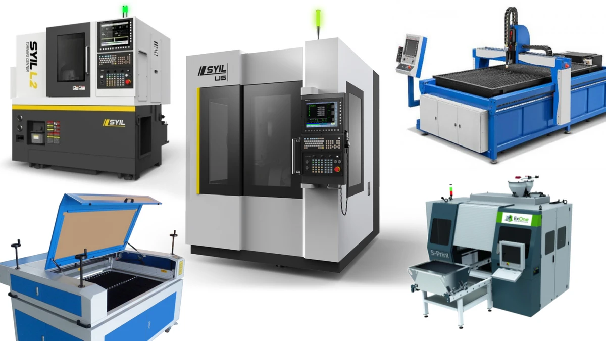
Essential Machine Types for Large Component Manufacturing
Now that you understand what qualifies as large part machining, the next question becomes obvious: what equipment actually handles these massive workpieces? Not all large cnc machines are created equal, and selecting the wrong machine type for your project can mean the difference between success and costly failure.
The machinery used for large component manufacturing represents significant capital investment—we're talking about equipment that can fill an entire facility bay. But beyond sheer size, these machines offer specialized configurations designed to address the unique challenges of oversized parts. Let's break down the primary machine types you'll encounter and when each one makes sense.
Horizontal vs Vertical Configurations for Oversized Components
When you're evaluating a large cnc milling machine for oversized components, the spindle orientation fundamentally changes what's possible. Understanding this distinction helps you match the right machine to your specific application.
Horizontal Boring Mills position the spindle horizontally, allowing the cutting tool to approach the workpiece from the side. According to industry technical resources, this configuration offers superior stability during cutting operations—particularly critical when machining heavy, bulky stock. The horizontal orientation enables efficient chip evacuation since gravity naturally pulls chips away from the cutting zone, preventing tool overheating and extending tool life.
These machines excel at applications like engine blocks, transmission housings, and large structural components where deep cuts and extensive surface milling are required. Horizontal cnc machining services are particularly valuable in automotive and aerospace industries where tight tolerances must be maintained across massive surfaces.
Vertical Turning Lathes (VTLs) flip the traditional lathe concept on its head—literally. With a vertical spindle and a rotating horizontal table, VTLs handle heavy, disk-shaped components that would be impractical to mount in a horizontal configuration. Imagine trying to secure a 5,000-pound turbine housing on a horizontal lathe. The vertical orientation lets gravity work in your favor, keeping the workpiece stable without excessive clamping forces that could cause distortion.
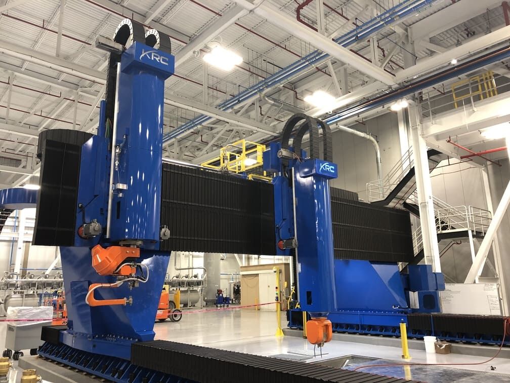
Gantry Mills represent the workhorses of large cnc mill operations. These machines feature a bridge structure that spans across the workpiece, with the spindle mounted on a moving crossrail. This configuration provides exceptional rigidity and enables machining of extremely long parts—some gantry mills can handle work envelopes exceeding 30 feet in length. When you need to machine aircraft wing spars or large structural weldments, a gantry configuration is often the only practical option.
Large-Envelope 5-Axis Machines combine massive work envelopes with the ability to approach the workpiece from virtually any angle. As CBM Precision Parts notes regarding their Mighty Viper x242, some bridge mills now offer work envelopes reaching 398 x 165 x 118 inches—that's over 33 feet of X-axis travel. The variable crossrail design on advanced machines allows operators to adjust spindle-to-table distance, maximizing both work envelope and spindle stability.
Machine Envelope Specifications That Matter
When you're evaluating whether a shop can handle your large component, understanding envelope specifications becomes critical. A cnc machine big enough for your part isn't just about overall dimensions—it's about understanding what each specification actually means for your project.
Here's what typical capacity looks like across different machine types:
| Machine Type | Typical Envelope Size | Best Applications | Precision Capabilities |
|---|---|---|---|
| Horizontal Boring Mill | 72" x 120" table, 60"+ spindle travel | Engine blocks, gearboxes, large housings, deep boring operations | ±0.001" to ±0.0005" depending on size |
| Gantry Mill | Up to 400"+ X-travel, 160"+ Y-travel | Aerospace structures, weldments, long prismatic parts | ±0.002" to ±0.001" across full envelope |
| Vertical Turning Lathe | 30" OD x 80" length (and larger) | Turbine housings, large flanges, ring-shaped components | ±0.001" on diameter, ±0.002" on length |
| 5-Axis Bridge Mill | Variable, up to 398" x 165" x 118" | Complex aerospace parts, multi-sided machining, impellers | ±0.001" to ±0.0005" with in-process probing |
| Floor-Type Boring Mill | Unlimited X-travel (rail-mounted), 80"+ Y-travel | Extremely long parts, press frames, mining equipment | ±0.002" to ±0.001" with laser compensation |
Notice how precision capabilities vary with size? This isn't a limitation of the machines themselves—it reflects the physical realities of thermal expansion, tool deflection, and positioning accuracy across extended distances. A big cnc milling machine can certainly achieve tighter tolerances on localized features, but holding those same tolerances across a 20-foot span requires sophisticated compensation strategies.
One often-overlooked specification is spindle power. Large CNC machines typically feature spindles ranging from 50 to over 100 horsepower, enabling aggressive material removal rates that keep cycle times reasonable despite the massive amount of material being removed. High-torque spindle options, as mentioned in reference to aerospace, heavy construction, and energy applications, allow shops to take deeper cuts without sacrificing surface finish quality.
Another critical factor? Pallet changers and automation capabilities. Machines like advanced bridge mills often include two-pallet changers that enable unattended operations. While one pallet is being machined, operators can load, unload, and inspect parts on the second pallet. For large parts with extended cycle times, this automation dramatically improves machine utilization.
Understanding these specifications helps you ask the right questions when evaluating potential machining partners. But even the most capable machine won't deliver quality results if precision challenges aren't properly managed—which brings us to the realities of maintaining accuracy at scale.
Precision Challenges and Tolerance Realities at Scale
Here's something most shops won't tell you upfront: the precision you can achieve on a 2-inch part is fundamentally different from what's realistic on a 20-foot component. It's not that large CNC machines lack capability—it's that physics works against you in ways that simply don't matter at smaller scales.
When you're producing precision cnc machining parts at scale, every factor that affects accuracy gets amplified. Temperature fluctuations that cause negligible movement in small components create significant dimensional shifts across large workpieces. Tool deflection that's imperceptible in standard operations becomes a major accuracy killer when reaching deep into cavities. Understanding these challenges—and knowing how experienced shops address them—separates successful large part projects from costly failures.
How Thermal Expansion Affects Large Workpiece Accuracy
Imagine you're machining an aluminum component that's 10 feet long. A temperature increase of just 10°F causes that part to grow by approximately 0.014 inches. Sounds minor? That dimensional change alone can push you outside tolerance on precision features—and the problem compounds during extended machining cycles.
According to Frigate's technical analysis, thermal stability plays a major role in ensuring precision in large CNC machined parts. Variations in temperature during machining cause dimensional drift and distortion, particularly in long production cycles where parts may be on the machine for hours or even days.
The thermal challenge operates on multiple levels:
- Workpiece Expansion: As material heats from cutting operations and ambient temperature changes, the part physically grows—unevenly in many cases, since areas being actively cut heat faster than areas waiting for subsequent operations
- Machine Structure Movement: The machine tool itself expands and contracts with temperature changes, affecting spindle position relative to the worktable
- Cumulative Effects: When machining a large component over multiple shifts, morning-to-afternoon temperature variations can cause enough movement to create measurable errors between features machined at different times
In aerospace manufacturing, studies referenced by industry experts show that deviations as small as 0.002 inches can compromise component integrity. When you're working with parts spanning multiple feet, achieving this level of consistency requires deliberate thermal management strategies that go far beyond standard shop practices.
Managing Tool Deflection in Extended Reach Operations
Picture this scenario: you need to machine a pocket that's 18 inches deep in a large structural component. The cutting tool must extend far from the spindle to reach the work surface, and every inch of extension amplifies the forces trying to bend that tool away from its intended path.
Seco Tools' technical guidance explains that in long-reach and extended-tool machining, the cutting edges operate at a considerable distance from the tool holder and its connection to the machine. This results in unwanted vibration, radial deflection, and bending of the tool due to mechanical loads.
The consequences of tool deflection extend beyond simple dimensional errors:
- Radial Deflection: Pushes the tool sideways, affecting accuracy and limiting achievable cutting depths
- Tangential Deflection: Forces the tool downward and away from the workpiece centerline, reducing clearance angles and causing rubbing rather than clean cutting
- Vibration and Chatter: Extended tooling magnifies dynamic machining forces, creating surface finish problems and accelerating tool wear
Without proper compensation, the negative impacts include poor surface finishes, loss of precision, rapid tool wear, tool failure, and potentially serious machine damage. For shops producing cnc precision machined parts at scale, mastering deflection management isn't optional—it's essential for survival.
Realistic Tolerance Expectations by Part Size
One of the most important conversations to have with any large precision machining provider involves honest tolerance discussions. What's achievable on a 6-inch part often isn't realistic across a 6-foot span, regardless of equipment quality.
As Technox Machine's analysis notes, factors that typically influence machining accuracy negatively are magnified when parts are larger. This means careful consideration needs to be placed on monitoring and countering these factors.
Here's a realistic view of tolerance expectations for high precision machining services working with large components:
- Local Feature Tolerances: Individual holes, pockets, and surfaces can typically hold ±0.001" or tighter, similar to smaller parts
- Feature-to-Feature Across Short Distances: ±0.001" to ±0.002" is achievable with proper process control
- Feature-to-Feature Across Full Part Length: ±0.002" to ±0.005" becomes more realistic for parts spanning several feet, depending on material and environmental controls
- Flatness and Straightness Over Long Spans: ±0.003" to ±0.010" per foot of length, varying significantly with material stability and stress relief status
These aren't limitations to hide from—they're physical realities that experienced shops plan around. The key is establishing realistic expectations upfront and designing processes that achieve required tolerances where they actually matter functionally.
Mitigation Strategies That Actually Work
Knowing the challenges is only half the battle. Here's how experienced precision cnc parts manufacturers address these accuracy obstacles:
- Temperature-Controlled Environments: Climate-controlled machining areas maintain consistent temperatures, often within ±2°F, minimizing thermal-induced dimensional changes. Some advanced facilities stabilize both air temperature and coolant temperature for maximum consistency.
- Strategic Machining Sequences: Rather than completing all operations on one end before moving to the other, experienced programmers sequence operations to balance heat distribution and allow cooling between passes. Performing semi-finish passes and measuring between them before taking finishing passes is key to achieving strict tolerances.
- In-Process Measurement: Probing systems integrated into the machining cycle verify dimensions before critical operations, allowing real-time adjustments. As Frigate's approach demonstrates, laser trackers and optical CMMs provide non-contact measurements ensuring accuracy during production.
- Stress Relief Operations: Material stress causes distortions that appear after machining when internal tensions redistribute. For critical large components, stress relief heat treatment between roughing and finishing operations prevents post-machining movement.
- Vibration-Damping Tooling: Specialized tool holders with internal damping mechanisms counteract the vibration tendencies of extended-reach cutting. These solutions can enable long overhang operations at speeds twice as fast as traditional tools while maintaining surface finish quality.
- Adaptive Machining Parameters: When engaging tools with flute lengths exceeding two times the diameter, experienced operators reduce surface footage and feed-per-tooth to minimize deflection. Similarly, when tools extend more than four times their diameter from the holder, axial depth of cut reductions become essential.
The bottom line? Achieving precision at scale requires planning, investment in environmental controls, and process discipline that goes well beyond what standard machining demands. Shops that understand these realities—and communicate them honestly—are the ones most likely to deliver large cnc precision machined parts that actually meet your requirements.
Of course, even the most sophisticated precision strategies depend on one fundamental capability: holding that massive workpiece securely without inducing the very distortions you're trying to avoid.
Workholding Strategies for Oversized Components
You've got the right machine, you understand the precision challenges, but here's a question that trips up even experienced engineers: how do you actually hold a 2,000-pound workpiece steady while cutting tools exert thousands of pounds of force against it? This is where large component machining success often lives or dies.
Workholding for oversized parts isn't just about clamping harder. Apply too much pressure and you'll distort the very part you're trying to machine accurately. Too little, and the workpiece shifts mid-cut—ruining the part and potentially damaging expensive equipment. The solution lies in strategic fixture design, smart clamping distribution, and careful datum management across multiple setups.
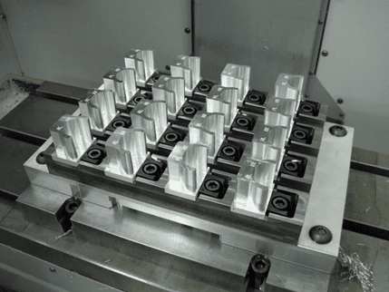
Custom Fixture Design for Oversized Workpieces
When standard vises and clamps can't handle the job, custom fixtures become essential. But designing effective workholding for large parts requires understanding forces that smaller components never encounter.
Think about what happens when a heavy workpiece sits on a machine table. Gravity alone creates stress concentrations at support points. Add cutting forces pushing laterally against the part, and you've got a complex loading scenario that requires engineering analysis—not just bigger clamps.
According to PTSMAKE's manufacturing guidance, the fixture becomes as critical as the cutting tool itself for complex parts. The goal is providing maximum rigidity with minimum clamping force, distributing pressure evenly to avoid damage or distortion.
Several workholding approaches prove effective for large part vertical machining and horizontal operations:
- Modular Workholding Systems: Grid-plate systems with T-slots at regular intervals allow flexible clamp positioning without custom machining. These systems accommodate various part geometries using standardized components that can be reconfigured between jobs.
- Vacuum Table Applications: For large, flat sheet materials, vacuum workholding provides uniform clamping force across the entire surface. As DATRON's technical documentation explains, a 9-inch square piece under vacuum experiences over 1,190 pounds of clamping force at sea level—and this scales linearly with surface area.
- Multi-Point Clamping Strategies: Rather than relying on a few high-force clamps, distributing holding force across many points prevents localized distortion. This approach is especially critical for thin-walled or flexible components.
- Sacrificial Support Structures: Adding temporary support features—machined away in final operations—provides rigidity during critical cuts without affecting the finished part geometry.
The engineering challenge intensifies when supporting heavy workpieces without inducing distortion. A large aluminum plate might deflect measurably under its own weight if supported only at the edges. Strategic support placement—often using adjustable jack screws or conformable supports—maintains flatness while the part is machined.
Multi-Setup Datum Transfer Strategies
Here's where large part machining services face their trickiest challenge: when a workpiece requires machining on multiple sides or exceeds a single machine's envelope, how do you maintain accuracy between setups?
Every time you unclamp and reclamp a part, you introduce potential error. As manufacturing experts note, it's impossible to relocate a part with perfect, zero-error repeatability. These tiny inaccuracies accumulate with each setup—a phenomenon called tolerance stack-up that can push critical dimensions out of spec.
Successful datum transfer depends on establishing clear reference points and using them consistently. Consider how medium to large part horizontal machining operations typically proceed:
- Establish Primary Datum Features First: Machine the surfaces that will serve as reference points for all subsequent operations before any other features. These datum surfaces must be accessible for probing or physical contact in later setups.
- Design Fixture Locators Around Datums: Create fixture elements that precisely engage the primary datum features. Precision dowel pins, machined locating surfaces, or dedicated locating holes provide repeatable positioning.
- Verify Position Before Cutting: Use on-machine probing to confirm workpiece location after each setup. Compare measured positions to expected values and apply offsets as needed before machining begins.
- Document and Track Cumulative Error: Measure critical features after each setup, tracking how dimensional variation accumulates. This data helps identify when tolerance stack-up approaches limits.
- Plan Operations to Minimize Setups: Group operations that share datum references. Machine all features requiring access from one direction before reclamping for another orientation.
For extremely critical applications, some shops machine dedicated tooling balls or reference surfaces into non-functional areas of the workpiece. These precision features provide consistent pickup points that laser trackers or CMM equipment can locate to micron-level accuracy, regardless of how many times the part moves between machines.
The investment in proper workholding strategy pays dividends beyond accuracy. Well-designed fixtures reduce setup time—a major cost driver in large part machining where setup can consume hours. They also improve safety by securing heavy workpieces against unexpected movement during aggressive cutting operations.
With workholding fundamentals covered, another critical factor awaits: selecting materials that behave predictably at scale while meeting your performance requirements.
Material Selection Considerations for Large Part Success
You've secured the right equipment and developed solid workholding strategies. But here's a factor that can undermine even the most carefully planned project: choosing the wrong material for your large component. When you're machining parts that span several feet, material behavior at scale becomes a make-or-break consideration.
What works beautifully for small cnc milled parts often creates headaches at larger dimensions. Thermal expansion that's negligible in compact components becomes a tolerance-busting problem across extended lengths. Weight that's easily managed on small workpieces requires heavy-duty fixturing and material handling for custom machined parts at scale. Understanding these material-specific challenges helps you specify components that actually succeed in large parts manufacturing.
Thermal Behavior Differences Across Material Types
Remember the thermal expansion discussion from earlier? Here's where material selection directly impacts that challenge. According to MISUMI's thermal expansion reference data, different materials expand at dramatically different rates—and this difference matters enormously for oversized cnc mechanical parts.
Consider this scenario: you're machining a 10-foot-long component, and the shop temperature rises 15°F during an extended cutting cycle. Depending on your material choice, here's what happens:
- Aluminum (CTE: 21-24 × 10⁻⁶/°C): The part grows approximately 0.021 to 0.024 inches—potentially pushing precision features out of tolerance
- Carbon Steel (CTE: 11-13 × 10⁻⁶/°C): Growth drops to roughly 0.011 to 0.013 inches—nearly half the aluminum movement
- Titanium (CTE: 8.6 × 10⁻⁶/°C): Even less expansion at approximately 0.009 inches—excellent dimensional stability
- Stainless Steel 304 (CTE: 17.3 × 10⁻⁶/°C): Middle ground at about 0.017 inches of growth
As PEKO Precision's manufacturing experts note from over 150 years of combined experience, temperature control of both machinery and base material is vitally important. They've seen rejectable variances between on-machine measurements and quality control lab measurements simply because coolant systems chilled parts out of tolerance, causing them to grow once warmed.
The thermal challenge extends beyond simple expansion. Different materials conduct heat differently during cutting operations. Aluminum's excellent thermal conductivity disperses cutting heat quickly, while titanium's poor conductivity concentrates heat at the tool-workpiece interface. This affects not just dimensional stability but also tool life and surface finish quality.
When Material Weight Becomes a Machining Factor
Imagine loading a steel billet that weighs 3,000 pounds onto a machine table. Now picture the same-sized aluminum billet at roughly 1,000 pounds. The weight difference fundamentally changes everything about how you handle, fixture, and machine these parts.
Weight impacts large component manufacturing in several critical ways:
- Fixturing Requirements: Heavy steel components may self-locate under gravity but require robust fixtures to resist cutting forces. Lighter aluminum parts need more aggressive clamping to prevent movement during aggressive cutting.
- Machine Table Capacity: Every machine has weight limits. A table rated for 5,000 pounds handles steel parts of smaller dimensions than equivalent aluminum components.
- Material Handling: As PEKO's experts emphasize, proper crane and lifting equipment becomes essential. A wrongly-placed strap or lifting eye can cause large machined parts to buckle under their own weight during removal.
- Deflection During Machining: Heavy workpieces sag between support points. A long steel bar spanning two fixtures may deflect measurably at center, requiring additional support to maintain flatness.
For applications where weight drives design—aerospace, transportation, and portable equipment—material selection often starts with density requirements and works backward to find acceptable machining tradeoffs.
Material Comparison for Large Part Applications
Selecting the right material requires balancing multiple factors simultaneously. This comparison helps you evaluate how common cnc machines parts materials perform across the critical parameters for oversized components:
| Material | Thermal Expansion Rate (×10⁻⁶/°C) | Weight Factor (Relative Density) | Stress Relief Needs | Machining Considerations |
|---|---|---|---|---|
| Aluminum Alloys (6061, 7075) | 21-24 | Low (2.7 g/cm³) | Moderate—recommended for tight-tolerance parts | Excellent machinability, high speeds possible, watch for work hardening in some alloys. Chips evacuate easily. |
| Carbon Steel (1018, 4140) | 11-13 | High (7.85 g/cm³) | High—essential for precision work to prevent post-machining distortion | Good machinability, moderate speeds. Higher cutting forces require rigid setups. Watch for work hardening. |
| Stainless Steel (304, 316) | 14.4-17.3 | High (8.0 g/cm³) | High—particularly for austenitic grades prone to stress cracking | Challenging machinability, lower speeds required. Gummy chips, work hardening concerns. Requires sharp tooling. |
| Titanium (Ti-6Al-4V) | 8.6 | Medium (4.43 g/cm³) | Moderate to High—depending on part geometry and prior processing | Difficult to machine, very low speeds, high tool wear. Excellent strength-to-weight. Requires specialized tooling and coolant strategies. |
Stress Relief: The Hidden Requirement
Here's something that catches many buyers off guard: material stress doesn't disappear just because you've received a nicely machined part. Internal stresses locked into the material during rolling, forging, or previous machining operations wait for their chance to release—often warping your precision component after it leaves the shop.
For large parts, this problem intensifies. A 10-foot steel weldment with residual stress can bow measurably after machining removes constraining material. The larger the part, the more material gets removed, and the greater opportunity for stress redistribution.
Stress relief requirements vary by material:
- Aluminum: Generally more stable, but precision parts benefit from stress relief heat treatment between roughing and finishing. Some alloys (particularly 7075) carry significant residual stress from heat treatment.
- Carbon Steel: Almost always requires stress relief for precision applications. Weldments absolutely demand it. Standard practice involves heating to 1,100-1,200°F, holding, then slow cooling.
- Stainless Steel: Austenitic grades are particularly stress-sensitive. Solution annealing may be required for maximum stability, though this affects hardness and strength.
- Titanium: Stress relief temperatures must be carefully controlled to avoid affecting material properties. Essential for parts with significant material removal.
As manufacturing guidance from Ethereal Machines emphasizes, understanding your project's specific requirements is the first step in making informed material decisions. For large parts, this means considering not just the finished part's performance requirements, but how the material will behave throughout the entire manufacturing process.
The bottom line? Material selection for large components requires thinking beyond basic strength and cost comparisons. Thermal behavior, weight implications, and stress relief needs directly impact whether your project achieves required tolerances—or becomes an expensive lesson in material science. With the right material specified, the next consideration becomes understanding which industries demand these oversized components and what unique requirements they bring.
Industry Applications Demanding Large Part Expertise
Now that you understand the materials that make large part machining possible, where do all these oversized components actually end up? The answer spans some of the world's most demanding industries—each bringing unique requirements that push precision machining services to their limits.
What makes these applications fascinating isn't just the scale of the parts. It's how each industry layers specific certifications, material specifications, and inspection standards on top of the already-challenging dimensional requirements. A wind turbine hub and a defense vehicle chassis might share similar dimensions, but the paths to producing them couldn't be more different.
Aerospace Structural Component Requirements
When you're producing components that fly, failure isn't an option. Aerospace structural parts represent some of the most demanding applications in large machining, combining extreme precision requirements with rigorous certification processes.
According to Neway Precision's aerospace manufacturing documentation, structural components must function reliably under high aerodynamic loads, thermal cycling from -55°C to 200°C, and prolonged vibration exposure—all while maintaining minimal weight. Typical aerospace structural parts requiring large cnc machining part capabilities include:
- Wing Spars and Ribs: Primary load-bearing structures spanning multiple feet, often machined from solid aluminum or titanium billets to eliminate assembly joints
- Fuselage Bulkheads: Critical structural frames requiring tolerances tighter than ±0.01 mm on load-bearing features
- Engine Pylons: High-stress mounting structures connecting engines to wings, demanding exceptional fatigue resistance
- Landing Gear Components: Massive forged and machined assemblies handling extreme impact loads during touchdown
What sets aerospace apart is the certification burden. Heavy machining services targeting this sector must maintain AS9100 certification—the aerospace-specific quality management standard. Parts undergo extensive non-destructive testing including ultrasonic inspection for internal voids, radiographic testing for weld integrity, and dye penetrant inspection for surface cracks.
The material requirements are equally stringent. Titanium alloys like Ti-6Al-4V dominate high-stress applications, offering tensile strength exceeding 900 MPa at roughly half the weight of steel. Aluminum 7075-T6 remains the workhorse for airframe structures. Every material lot must be traceable, with mill certifications documenting chemical composition and mechanical properties.
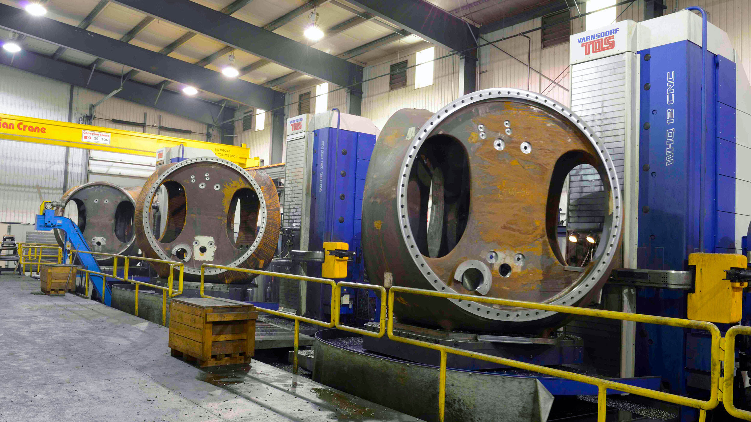
Energy Sector Applications from Wind to Oil and Gas
The energy industry's appetite for large machined components spans two very different environments—towering wind turbines and harsh subsea drilling operations. Both demand precision at scale, but the specific requirements diverge significantly.
Wind Energy Components
A modern wind turbine hub—the central casting connecting blades to the drivetrain—can exceed 15 feet in diameter and weigh over 50,000 pounds. These components require large machining capabilities that few shops possess:
- Hub Assemblies: Massive ductile iron or steel castings requiring precision boring of blade mounting interfaces and main shaft connections
- Main Bearing Housings: Critical fits that must maintain alignment under dynamic loads and temperature swings from desert heat to arctic cold
- Yaw and Pitch Systems: Gear housings and mounting structures requiring consistent tolerances across large diameters
Wind components face unique challenges: they must survive 20+ year service lives with minimal maintenance in remote locations. This drives requirements for corrosion-resistant coatings, precise surface finishes on bearing surfaces, and extensive documentation for warranty support.
Oil and Gas Applications
The oil and gas sector demands components built for extreme pressures, corrosive environments, and zero-tolerance safety requirements. According to Johnson Centrifugal's oil and gas documentation, companies are finding themselves in more remote and challenging environments than ever before, making quality component requirements higher than at any previous time.
Typical large part applications include:
- Valve Bodies: High-pressure housings machined from specialty alloys like C93800 and Inconel to handle corrosive well fluids
- Manifolds: Complex multi-port assemblies distributing flow between wells and processing equipment
- Blowout Preventers: Safety-critical components requiring exceptional material integrity and precise sealing surfaces
- Subsea Connector Housings: Components rated for deep-water pressures exceeding 15,000 PSI
Material specifications in oil and gas applications often call for exotic alloys resistant to hydrogen sulfide, chlorides, and extreme temperatures. ASTM A297 heat-resistant alloys and ASTM B369 copper-nickel alloys appear frequently in specifications. Every component faces rigorous pressure testing and documentation requirements before deployment.
Defense and Heavy Equipment Requirements
CNC machining for the transportation industry and defense sectors presents yet another set of challenges—components must survive operational conditions that would destroy commercial equipment.
As Marberry Machine's defense manufacturing overview explains, military equipment operates in environments ranging from corrosive seas to dusty cityscapes, where a single component failure can mean the difference between mission success and failure. Specialty cnc parts production for defense typically includes:
- Vehicle Hull Components: Armor-grade steel and aluminum structures requiring precise fit for assembly and consistent ballistic protection
- Weapon System Mounts: High-precision platforms maintaining accuracy under extreme recoil forces
- Naval Shaft Sleeves: Large-diameter turning operations with tight concentricity requirements for propulsion systems
- Breech Ring Mechanisms: Complex geometries requiring multiple machining operations with exacting tolerances
Defense contracts introduce ITAR (International Traffic in Arms Regulations) compliance requirements, restricting which facilities can even quote on certain work. Shops serving this sector maintain JCP certification and CAGE codes for government contracting. Material traceability extends beyond commercial requirements—every fastener, every weld rod, and every inch of base material must be documented.
Mining equipment frames and heavy construction components share similar durability demands, though certification requirements differ. These industries prioritize impact resistance, fatigue life under cyclic loading, and field repairability. Weldable steel grades dominate, with stress relief and thorough NDT inspection ensuring components survive punishing service conditions.
Across all these industries, one common thread emerges: the inspection and quality verification methods must match the scale of the components being produced. Standard measurement approaches often fall short when parts exceed conventional CMM envelopes.
Quality Control and Inspection Methods for Large Parts
Here's a challenge that catches many buyers off guard: you've invested in precision large part cnc machining, the component looks beautiful, but how do you actually verify those critical dimensions? When your part is longer than the measurement equipment designed to inspect it, traditional quality control methods hit a wall.
Inspecting oversized components requires measurement technologies and strategies that differ fundamentally from standard parts verification. The same scale that makes large capacity machining challenging also creates unique inspection hurdles—and understanding these limitations helps you set realistic expectations and ask the right questions when evaluating potential suppliers.
When Traditional CMMs Reach Their Limits
Traditional coordinate measuring machines have served as the gold standard for precision inspection for decades. But imagine trying to measure a 15-foot aerospace spar on a CMM with a 48-inch envelope. It simply won't fit—and that's just the beginning of the challenges.
According to ZEISS metrology guidance, available measurement systems have different recommended part size limits—they can measure a part within that size range, no more, no less. For large scale machining applications, traditional bridge-type CMMs present several limitations:
- Physical Envelope Constraints: Most shop-floor CMMs max out at work volumes around 60 x 80 x 40 inches. Parts exceeding these dimensions simply cannot be measured on standard equipment.
- Environmental Sensitivity: Large CMMs require temperature-controlled rooms, often maintained at 68°F ±1°. Moving massive parts into and out of these controlled environments introduces thermal stabilization delays—sometimes hours for heavy steel components to reach equilibrium.
- Measurement Uncertainty at Extremes: Even large CMMs experience degraded accuracy at the edges of their working volume. Uncertainty specifications of ±0.0002" at center can grow to ±0.001" or more at maximum reach.
- Throughput Limitations: Each measurement takes time. As ZEISS notes, even 30 seconds of scanning time adds up when you're measuring several parts per hour—and large parts require exponentially more measurement points.
For large bore machining applications requiring internal diameter verification, physical access compounds the problem. A probe arm must reach deep into cavities, and standard CMM configurations often lack the extension capability for deep-bore measurements on oversized components.
Alternative Measurement Technologies for Oversized Parts
When traditional CMMs can't handle the job, specialized measurement technologies step in. Each offers distinct advantages depending on your part geometry, accuracy requirements, and production environment.
Portable Arm CMMs
These articulated arm devices bring measurement capability directly to the workpiece—even while it remains fixtured on the machine. Portable arms typically offer measurement volumes up to 12 feet in diameter and can be repositioned around larger parts using leap-frog techniques with common reference points.
Key considerations for portable arm selection include:
- Accuracy: Volumetric accuracy typically ranges from ±0.001" to ±0.002" depending on arm length. Shorter arms deliver better precision.
- Part Complexity: Advanced arms handle everything from simple prismatic features to complex contoured surfaces, though operator technique significantly affects results.
- Ease of Use: As ZEISS emphasizes, the device should be easy for workers to operate. Training requirements and measurement repeatability between operators vary by system.
Laser Tracker Systems
For the largest components—think aircraft fuselages or wind turbine structures—laser trackers provide measurement capability across volumes exceeding 100 feet in diameter. These systems track a reflective target moved across the part surface, recording coordinates with remarkable accuracy.
Laser trackers excel at:
- Large-Scale Alignment: Verifying that features across an entire assembly align correctly
- In-Process Verification: Quick checks between machining operations without removing parts from fixtures
- Portable Deployment: Single-operator systems that set up in minutes and work on the shop floor
Accuracy specifications for quality laser trackers reach ±0.0005" + 0.0000005"/inch of distance—impressive performance that degrades only slightly across extended ranges.
Photogrammetry and 3D Scanning
According to SHINING 3D's technical documentation, modern 3D scanning systems now offer scan speeds up to 3,460,000 points per second, enabling rapid full-surface inspection of large components. These non-contact methods capture millions of data points, creating digital twins of physical parts for comparison against CAD models.
3D scanning proves particularly valuable for:
- First-Article Inspection: Comprehensive verification of complex geometries before production commitment
- Freeform Surface Verification: Checking contoured surfaces that would require thousands of individual touch-probe measurements
- Fragile or Flexible Parts: Non-contact measurement eliminates probe forces that could deflect thin-walled structures
In-Process Inspection Strategies
Waiting until machining completes to discover dimensional problems wastes time and money. For large parts with extended cycle times, in-process inspection catches issues while correction remains possible.
Effective in-process strategies include:
- On-Machine Probing: Touch probes integrated into the machining cycle verify critical dimensions between operations. If roughing cuts leave insufficient stock for finishing, operators adjust before wasting hours on subsequent operations.
- Semi-Finish Measurement Holds: Pausing between roughing and finishing to measure parts—allowing stress relief if needed—before taking final cuts that determine part conformance.
- Statistical Process Control: Tracking dimensional trends across multiple parts identifies drift before tolerances are violated. This proves especially valuable in production runs of similar large components.
Documentation and Traceability Requirements
For regulated industries, the inspection report matters as much as the measurements themselves. Aerospace AS9102 first-article inspection reports, automotive PPAP documentation, and defense contract DID requirements all demand specific evidence formats.
Complete documentation packages typically include:
- Dimensional Inspection Reports: Every specified dimension verified against tolerance, with actual measured values recorded
- Material Certifications: Mill test reports tracing raw material to specific heat lots with chemical composition and mechanical property verification
- Process Certifications: Heat treatment records, NDT inspection results, and special process documentation from certified suppliers
- Measurement System Traceability: Calibration records proving inspection equipment accuracy traces to NIST standards
The bottom line? Quality verification for large parts requires planning measurement strategy alongside machining strategy. Shops that invest in appropriate inspection technology—and understand which method suits each application—deliver confidence along with components. Of course, all these capabilities directly impact what you'll pay for large part machining, which brings us to the cost factors that drive project budgets.
Cost Factors and Smart Budgeting for Large Part Projects
You've seen the equipment, understood the precision challenges, and learned about inspection requirements. Now comes the question that ultimately shapes every project: what's this going to cost? Large part machining carries a price tag that often surprises first-time buyers—and understanding what drives those costs helps you budget accurately and identify real opportunities for savings.
Here's what most shops won't explain upfront: the cost structure for oversized components differs fundamentally from standard machining. Setup time consumes a larger percentage of total cost. Material waste calculations change dramatically. And the decision between true large-capacity equipment versus creative workarounds can swing your budget by tens of thousands of dollars. Let's break down what actually drives pricing so you can make informed decisions.
Understanding Setup Time Impact on Project Costs
When you're machining a small part, setup might take 30 minutes. For large components requiring custom fixtures, precision alignment, and multiple reference verifications, setup can consume an entire shift—or more. This reality fundamentally changes the cost equation.
According to Xometry's cost analysis, set-up costs cover the costs incurred in preparation for actual machining, including CAD design, CAM preparation, and machine configuration. For large parts, these costs escalate dramatically because:
- Custom Fixture Fabrication: Standard workholding rarely accommodates oversized components. Designing and building dedicated fixtures adds engineering time and fabrication costs before any chips fly.
- Extended Alignment Procedures: Establishing datums across a 10-foot workpiece takes exponentially longer than aligning a palm-sized part. Laser tracker verification, precision indicator sweeps, and probe routines all consume hours.
- Material Handling Complexity: Moving multi-ton workpieces requires crane time, rigging expertise, and careful positioning. A fumbled lift can damage both the part and expensive machine components.
- Program Prove-Out: First-article runs on large parts carry significant risk. Cautious operators run reduced feeds initially, verify dimensions frequently, and adjust parameters—all adding time before production speeds.
Here's the critical insight: setup costs remain relatively fixed regardless of quantity. Xometry's data shows that cost per unit for a production volume of 1,000 parts runs approximately 88% less than a standalone unit. For large machining companies handling oversized components, this volume effect is even more pronounced because setup represents such a significant portion of single-piece costs.
This explains why contract machining services often quote dramatically different prices for prototype quantities versus production runs. The same heavy cnc machining operation that costs $15,000 for one piece might drop to $3,000 per unit at quantity ten—not because the machining changed, but because setup costs spread across more parts.
Material and Machine Time Cost Drivers
Beyond setup, two factors dominate large part pricing: what goes into the machine and how long it runs.
Material Waste Considerations
Large parts often start as massive billets or forgings, and significant material gets converted to chips. As FacFox's cost reduction guide explains, blank size directly affects CNC costs because material needs to be removed from all sides to ensure dimensional accuracy—leading to significant waste, especially for large batches.
Consider an aerospace structural component machined from a 500-pound aluminum billet that yields a 75-pound finished part. You've paid for 500 pounds of aerospace-grade aluminum, but 425 pounds became chips. At current aluminum prices, that's substantial cost tied up in scrap—even with recycling credits.
Commercial machining operations calculate buy-to-fly ratios (raw material weight divided by finished weight) as a key cost metric. Ratios of 10:1 or higher aren't unusual for complex large components, meaning 90% of purchased material gets machined away.
Machine Time Calculations
Heavy cnc machining equipment commands premium hourly rates. A large gantry mill might bill at $200-400 per hour, compared to $75-150 for standard machining centers. When your part requires 40 hours of machine time, that rate difference translates to thousands of dollars.
What extends machine time on large parts?
- Extended Travel Distances: Tools must traverse feet instead of inches between features, adding non-cutting time
- Conservative Cutting Parameters: Deeper cuts and extended tooling often require reduced speeds to manage deflection and vibration
- Multiple Operations: Parts requiring turning, milling, and boring may move between specialized machines—each with its own setup
- In-Process Verification: Stopping to measure critical features adds time but prevents costly scrap
The Large-Capacity Equipment Decision
Here's a question that deserves honest evaluation: does your part actually require dedicated large-capacity equipment, or could creative approaches using standard machines work?
True large-capacity machines cost more to purchase, operate, and maintain. These costs pass through to customers. But attempting workarounds on undersized equipment introduces risks: compromised accuracy from multiple setups, potential safety hazards, and extended lead times from inefficient processes.
The decision framework involves weighing several factors:
- Dimensional Requirements: Parts genuinely exceeding machine envelopes have no workaround option
- Tolerance Criticality: Features requiring tight relationships across the full part often demand single-setup machining that only large equipment provides
- Quantity: One-off prototypes might justify creative approaches; production runs typically favor purpose-built equipment
- Schedule: Workarounds usually take longer—sometimes the premium for proper equipment buys back schedule time
For best machining results on oversized components, honest assessment of whether your project truly requires large-capacity equipment—or whether it's being pushed onto inappropriate machines—helps you evaluate quotes intelligently.
Design Decisions That Drive Manufacturing Expenses
Perhaps the most powerful cost lever sits with you, the buyer. Design choices made early in development lock in manufacturing costs that no amount of supplier negotiation can recover. According to 6Sigma's DFM research, Design for Manufacturing is the practice of designing products with manufacturing in mind—anticipating and addressing potential production challenges before they arise.
For large parts, DFM principles translate into specific cost-saving strategies:
- Minimize Tight Tolerance Zones: As FacFox notes, tight tolerances necessitate intricate machining processes, extending processing time and requiring additional inspections. Specify precision only where function demands it—not across entire parts.
- Avoid Deep Pockets and Thin Walls: Deep cavities require extended tooling with deflection challenges. Thin walls machine slowly to avoid vibration. Both drive costs significantly higher than standard features.
- Design for Minimum Setups: Every time a part gets reclamped, you pay for alignment, verification, and the risk of datum transfer error. Parts designed for single-setup machining cost less than those requiring multiple orientations.
- Consider Near-Net-Shape Starting Material: Forgings, castings, or weldments closer to final geometry reduce machining time dramatically. The upfront investment in better blanks often pays back through reduced machine hours.
- Standardize Features Where Possible: Standard hole sizes enable fast drilling with standard tools. Non-standard holes require end mills that cut slower and cost more.
- Plan Inspection Accessibility: Features that can't be measured cost more because they require destructive testing or elaborate verification methods. Design critical dimensions where standard measurement equipment can reach them.
- Review Material Selection for Machinability: Free-machining alloys cut faster than difficult materials. If performance requirements permit, selecting more machinable grades directly reduces machine time costs.
The principle of simplification extends particularly to large parts. Every added feature multiplies machining time across an already-extended cycle. Eliminating unnecessary complexity before design release delivers savings no manufacturing optimization can match.
Getting Accurate Quotes
Armed with understanding of cost drivers, you're positioned to get—and evaluate—meaningful quotes from large machining companies. Provide complete information upfront: 3D models, tolerance specifications, material requirements, quantity, and delivery needs. Incomplete RFQs generate padded quotes as suppliers hedge against unknown requirements.
When reviewing quotes, look beyond bottom-line pricing. Understand what's included: Does the quote cover first-article inspection? Material certification? Stress relief operations? Shops quoting significantly below competitors may be excluding necessary operations—or underestimating the true scope of large part challenges.
The relationship between cost and capability becomes even more critical when selecting your machining partner. Understanding what separates qualified large part suppliers from shops overreaching their true capabilities helps you avoid expensive lessons.
Selecting the Right Large Part Machining Partner
You've mastered the technical requirements and understand what drives costs. But here's where many projects stumble: choosing a supplier who can actually deliver. When you're sourcing cnc precision machining services for oversized components, the difference between a capable partner and one overreaching their abilities can mean the difference between project success and expensive failure.
The challenge? Every shop claims they can handle large parts. Sales teams show impressive equipment photos and promise tight tolerances. But how do you separate genuine capability from optimistic marketing? This buyer's guide gives you the questions, verification methods, and warning signs that reveal the truth before your project—and budget—pays the price.
Key Questions to Ask Before Committing
When evaluating potential large cnc machining services providers, surface-level conversations won't reveal true capability. You need to dig deeper with questions that expose actual experience versus aspirational claims.
According to Zenithin Manufacturing's supplier audit guide, the single most powerful shift you can make during evaluation is changing your questions from "Do you have...?" to "Show me how..." A "yes" to the first question is easy. The second requires proof.
Use these targeted questions when evaluating aluminum cnc machining services or any large part supplier:
- "Show me three similar parts you've completed in the last year." Any shop claiming large part expertise should have recent examples matching your size, material, and tolerance requirements.
- "Walk me through your process for a part this size." Listen for specific details about fixturing strategy, thermal management, and inspection methods. Vague answers signal inexperience.
- "What's your largest successfully completed part in this material?" Past performance predicts future capability better than equipment specifications.
- "How do you handle dimensional verification on parts exceeding your CMM envelope?" Shops without answers haven't solved this fundamental large part challenge.
- "Can I see your process capability data for similar tolerance requirements?" According to Kesu Group's selection criteria, robust quality assurance processes—including Cpk data demonstrating process capability—separate professional operations from those just meeting minimum standards.
Don't accept marketing materials as answers. A precision cnc machining company with genuine capability welcomes detailed questions because they've already solved these challenges and can demonstrate their solutions.
Certification Standards That Signal Capability
Certifications act as your first filter when evaluating potential suppliers. They don't guarantee success on your specific project, but they verify that a shop has invested in documented quality systems and passed independent audits.
According to Modo Rapid's certification analysis, certifications like ISO 9001, IATF 16949, and AS9100 signal a supplier's commitment to quality, traceability, and process control—reducing risks in production and supply chains.
Here's what each major certification tells you:
- ISO 9001: The baseline certification verifying documented quality control processes and continuous improvement practices. Consider this the minimum threshold for any serious supplier—think of it like a driver's license for manufacturing.
- IATF 16949: Tailored specifically for automotive applications, this certification adds requirements for defect prevention, Statistical Process Control (SPC), and advanced product quality planning. For automotive components, this certification is non-negotiable. Suppliers like Shaoyi Metal Technology maintain IATF 16949 certification backed by strict SPC protocols—exactly the verification standard you should seek for automotive applications.
- AS9100: The aerospace and defense standard layering additional safety, reliability, and traceability protocols onto ISO 9001 foundations. Required for flight-critical components.
- ISO 13485: Essential for medical device components, ensuring biocompatibility requirements and healthcare-specific traceability.
- ITAR Registration: Mandatory for defense projects involving controlled technical data and export-regulated components.
But here's the critical insight from Zenithin's audit guidance: a certificate proves they have a system, but your evaluation needs to prove they actually use it. Request random audit evidence—ask to see complete documentation trails for recent jobs. The smoothness and speed with which they produce these records reveals how deeply embedded their quality system really is.
Evaluating Lead Time and Capacity Claims
Lead time promises mean nothing without the capacity to deliver. Understanding how to evaluate these claims protects you from suppliers who accept orders they can't fulfill on schedule.
According to Kesu Group's reliability criteria, a factory's production capacity directly affects its ability to meet demand and deliver on time. Assessing capacity ensures the supplier can handle your project's volume and schedule.
When evaluating cnc machining services near me or distant suppliers, investigate these capacity factors:
- Current Machine Loading: Ask what percentage of their large-capacity equipment is currently committed. Shops running at 95% utilization have no buffer for your project delays or their own equipment issues.
- Shift Patterns: Single-shift operations have limited capacity to recover from problems. Multiple shifts and weekend availability indicate serious production capability.
- Workforce Depth: Large part machining requires experienced operators. Ask about operator experience levels and backup personnel for critical equipment.
- Material Lead Times: For exotic materials, sourcing can add weeks. Verify whether quoted lead times include material procurement or assume material in-house.
For projects requiring flexibility from prototyping through production volumes, evaluate whether suppliers can scale with your needs. Shaoyi Metal Technology exemplifies this scalability, offering rapid prototyping with lead times as fast as one working day while maintaining the capacity and quality systems to scale seamlessly to mass production—the kind of flexibility that prevents painful supplier transitions as your project evolves.
Red Flags That Signal Trouble
Experience teaches buyers to recognize warning signs before commitments are made. According to Zenithin's supplier assessment framework, even experienced procurement managers fall for predictable traps:
- The 'Perfect Sample' Trap: A flawless sample part arrives, but it was painstakingly crafted outside normal production flow. Always demand that samples include First Article Inspection reports and Cpk data proving repeatable capability—not one-time craftsmanship.
- Enthusiastic Sales, Silent Engineering: If the salesperson answers all technical questions while engineers remain quiet, you're not talking to the people who'll actually solve your problems. Bypass sales and directly assess engineering and quality personnel.
- Suspiciously Low Quotes: Prices significantly below competitors often exclude necessary operations—stress relief, inspection, documentation—or indicate underestimation of large part challenges.
- Vague Process Descriptions: Suppliers who can't articulate specific strategies for thermal management, fixturing, or datum transfer haven't developed them yet. Your project shouldn't be their learning experience.
- Resistance to Facility Visits: Legitimate operations welcome customer visits. Reluctance suggests the shop floor doesn't match the marketing presentation.
Whether you're sourcing from cnc machining Ohio suppliers or facilities across the globe, these red flags apply universally. Geographic proximity offers convenience for visits and shipping but doesn't substitute for genuine capability verification.
Vendor Evaluation Checklist
Before finalizing any large part machining partnership, verify these critical elements:
- Equipment Verification: Confirm machines matching your part requirements exist and are operational—not on order or recently decommissioned.
- Relevant Experience: Document three or more completed projects with similar size, material, and tolerance requirements.
- Certification Currency: Verify certifications are current and cover the specific facility quoting your work.
- Quality System Evidence: Review actual quality documentation from recent jobs, not just procedures manuals.
- Inspection Capability: Confirm measurement equipment and methods appropriate for your part dimensions and tolerance requirements.
- Financial Stability: As Zenithin's guidance emphasizes, a supplier with shaky financial foundation is a risk regardless of price. A cheap part from a supplier who fails mid-production is the most expensive part you'll ever buy.
- Communication Responsiveness: According to Kesu Group's criteria, response time for technical queries should be within 24 hours. Slow responses during quoting predict frustrating communication during production.
- Capacity Availability: Verify realistic timelines based on current loading, not optimistic best-case scenarios.
The investment in thorough supplier evaluation pays dividends throughout your project. Shops that welcome scrutiny typically deliver results; those that deflect detailed questions often disappoint when production challenges arise.
Remember: you're not just sourcing a part—you're selecting a partner whose capabilities directly impact your project success. The time spent verifying claims before commitment prevents far greater costs from discovering limitations after production begins.
Frequently Asked Questions About CNC Machining Large Parts
1. What are the 7 major parts of a CNC machine?
The seven key components of a CNC machine include the Machine Control Unit (MCU) which serves as the brain, input devices for loading programs, the drive system for axis movement, machine tools for cutting operations, feedback systems for accuracy monitoring, the bed and table for workpiece support, and the cooling system for thermal management. For large part machining, these components must be significantly more robust—with high-torque spindles, extended axis travel, and enhanced rigidity to handle oversized workpieces weighing thousands of pounds.
2. What is the hourly rate for a CNC machine?
CNC machining rates vary significantly based on machine type and capability. Standard machining centers typically bill $75-150 per hour, while large-capacity equipment like gantry mills and horizontal boring mills command premium rates of $200-400 per hour. These higher rates reflect the substantial capital investment in large-capacity equipment, specialized operator expertise, and extended setup times required for oversized components. For automotive applications, IATF 16949-certified facilities like Shaoyi Metal Technology offer competitive rates backed by SPC-controlled quality systems.
3. What size parts qualify as large CNC machining?
Industry professionals define large CNC machined components as those exceeding 24 inches in any single dimension or weighing more than 500 pounds. Parts longer than one meter typically require specialized large-capacity equipment because standard machines cannot accommodate them. Some advanced facilities handle parts up to 34 feet long using gantry mills and floor-type boring mills with travel ranges exceeding three meters along their main axis.
4. How do you maintain precision when machining large parts?
Maintaining precision at scale requires multiple strategies: temperature-controlled environments within ±2°F to minimize thermal-induced dimensional changes, strategic machining sequences that balance heat distribution, in-process measurement using probing systems and laser trackers, stress relief heat treatment between roughing and finishing operations, and vibration-damping tooling for extended-reach cutting. Realistic tolerance expectations include ±0.001" for local features, but ±0.002" to ±0.005" across full part lengths spanning several feet.
5. What certifications should a large part machining supplier have?
Essential certifications depend on your industry. ISO 9001 serves as the baseline for documented quality control. IATF 16949 is mandatory for automotive applications, adding requirements for defect prevention and Statistical Process Control. AS9100 covers aerospace and defense with enhanced safety and traceability protocols. ISO 13485 applies to medical device components. For defense projects, ITAR registration is required. Always verify certifications are current and request evidence of actual quality system implementation through documentation from recent jobs.