 Small batches, high standards. Our rapid prototyping service makes validation faster and easier —

Order CNC Parts Like A Pro: From Design Files To Delivery
Understanding the CNC Ordering Process
When you order CNC parts, you're doing more than simply purchasing components off a shelf. You're initiating a collaborative manufacturing relationship that transforms your digital designs into precision-engineered physical components. Unlike traditional procurement where you select from existing inventory, this process requires active participation in specifying exactly how your parts should be made.
Whether you're a first-time buyer navigating your initial quote request or an experienced engineer optimizing your procurement workflow, understanding what happens behind that "submit" button makes all the difference. This guide bridges the knowledge gap that most resources overlook—focusing on education rather than just pushing you toward a quick quote.
From Digital Design to Physical Part
The journey from CAD file to finished component involves multiple decision points that directly impact your results. When you submit an order to CNC manufacturing shops, your 3D model becomes the blueprint for every cut, drill, and finish operation. Contemporary machining systems can interpret part geometry directly from CAD files, but your input on materials, tolerances, and surface finishes shapes the final outcome.
Think of it this way: your design file tells the machine what to create, but your specifications tell it how to create it. Missing this distinction leads to revision cycles, unexpected costs, and delayed timelines.
Why CNC Ordering Has Evolved
Traditional manufacturing procurement often meant lengthy back-and-forth conversations, physical samples, and weeks of waiting. Today's precision CNC machining services have streamlined this process significantly. You can upload files, receive automated quotes, and track production—all from your desk.
However, this convenience comes with responsibility. As industry research highlights, miscommunication between design engineers and manufacturers remains one of the biggest challenges in sourcing custom parts. When requirements aren't clearly conveyed, the result is often inaccurate quotes or components that miss quality standards entirely.
Proper ordering preparation—including complete file specifications, clear tolerance callouts, and appropriate material selection—can reduce revision cycles by eliminating the guesswork that delays production and inflates costs.
The Modern Manufacturing Workflow
So what does successful CNC fabrication procurement actually involve? Throughout this guide, you'll learn the complete workflow: preparing design files that manufacturers can work with, selecting materials that match your application, specifying tolerances that balance precision with cost, and navigating the quote-to-delivery timeline.
We'll cover primary machining considerations like CNC turning and milling operations, help you understand pricing factors, and explain when CNC is the right choice over alternatives like 3D printing or injection molding. By the end, you'll approach your next order with the confidence that comes from truly understanding the process—not just clicking buttons and hoping for the best.
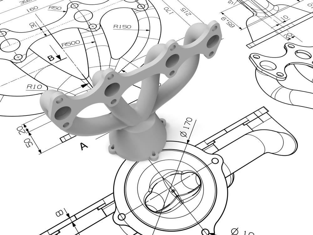
Preparing Your Design Files for Manufacturing
Your CAD file isn't just a visual representation of your part—it's the definitive blueprint that controls every cutting operation. When you order CNC machining parts, the quality of your design files directly determines how smoothly production proceeds. A well-prepared file translates into accurate quotes, fewer revision cycles, and components that match your specifications on the first run.
Yet here's where many first-time buyers stumble: they assume that a model looking correct on screen means it's ready for manufacturing. The gap between design intent and manufacturing reality catches countless engineers off guard. Let's bridge that gap by examining exactly what manufacturers need from your files.
Accepted File Formats and Best Practices
Not all file formats communicate geometric data with equal precision. When preparing files for CNC milling parts or turning operations, your format choice affects how accurately your design transfers to the CAM software that generates toolpaths.
STEP (.step or .stp) stands as the gold standard for CNC machining materials and part geometry. Governed by the ISO 10303 standard, STEP files capture exact NURBS geometry along with crucial topological information—faces, edges, and surfaces that connect seamlessly. This creates a true solid model rather than just graphical data, which is essential for complex 3D machining operations.
IGES (.igs or .iges) remains widely supported but primarily handles surface geometry. While functional, IGES files are more prone to surface continuity errors—small gaps or overlaps—when exporting complex solids. If you're working with legacy systems, IGES works, but STEP is generally preferred for robust solid modeling.
DXF/DWG formats serve a different purpose. These 2D drawing formats excel for profile machining, laser cutting, or waterjet operations. They accurately define lines, arcs, and polylines but lack the volumetric information needed for 3D CNC machine parts.
Native CAD formats (SolidWorks, Fusion 360, Inventor) can sometimes be accepted, though conversion to STEP before submission eliminates software compatibility issues.
Sounds complex? Here's the simple rule: when in doubt, export as STEP AP214, which supports geometry, color, and layer information while maintaining mathematical precision.
Design Features That Affect Machinability
A geometrically correct CAD model isn't automatically a manufacturable one. CNC machining relies on cylindrical cutting tools, which introduces physical constraints your design must accommodate.
Internal corner radii represent the most common issue. End mills cannot create true 90-degree internal corners due to their cylindrical geometry. Specify corner radii at least 1.2 times the radius of the smallest intended tool—typically a minimum of 0.030" (0.76mm) for standard operations. Sharp internal corners force manufacturers to use tiny, fragile tools that slow production and increase costs.
Aspect ratio and depth matter for pockets and slots. As cutting tools extend further from the spindle, rigidity decreases. Deep, narrow features cause tool deflection, chatter, and poor surface finish. Keep pocket depths reasonable relative to their width—generally no more than four times the tool diameter for reliable results.
Wall thickness affects part stability during machining. Thin walls vibrate under cutting forces, causing dimensional inaccuracy and surface defects. For aluminum, maintain minimum wall thicknesses of 0.040" (1mm); for steel, 0.060" (1.5mm) provides better rigidity.
Undercuts and inaccessible features require special consideration. Any geometry that a standard tool cannot reach from above needs either specialized tooling (like T-slot cutters), multi-axis machining, or design modification. If your part is intended for 3-axis work, eliminate undercuts or redesign for accessibility.
Pre-Submission Checklist for Your Files
Before uploading your files, run through this preparation checklist to catch issues that delay orders:
- Verify units and scale: Confirm your model uses the intended units (millimeters or inches) and exports at 1:1 scale. A model designed in inches but interpreted as millimeters creates a part scaled down by a factor of 25.4—an expensive mistake.
- Check for watertight geometry: Your solid model must be completely closed with no gaps between surfaces. Run your CAD software's geometry analysis to identify and repair open edges or non-manifold geometry that confuses toolpath calculations.
- Define coordinate systems clearly: Align your part's coordinate system with how it will be fixtured on the machine. Poorly defined datums force operators to guess your intended orientation, introducing alignment errors.
- Remove unnecessary features: Delete construction geometry, aesthetic details that don't affect function, and features like internal threads that will be added post-machining. Simplified geometry generates faster, more reliable toolpaths.
- Ensure feature accessibility: Verify that all machined features can be reached by standard cutting tools from your intended setup orientations. Flag any areas requiring special tooling or multi-axis access.
- Specify adequate corner radii: Check that all internal corners include radii compatible with standard end mill sizes—0.030" minimum for most applications.
- Maintain minimum wall thicknesses: Confirm walls and ribs meet material-appropriate minimums to prevent vibration and distortion during cutting.
When to Include 2D Technical Drawings
While 3D models drive the actual machining, technical drawings remain essential for communicating information that CAD geometry alone cannot convey. Include 2D drawings when your custom machined parts require:
- Specific tolerances tighter than standard machining allowances
- Thread specifications with defined pitch, class, and depth
- Surface finish requirements for particular features
- GD&T callouts for form, orientation, or position control
- Notes about edge treatments, deburring, or special handling
Your drawing serves as the visual reference operators check during production. Even when your CAD file is perfect, a clear drawing with dimensioned orthogonal views, section views for internal features, and a complete title block helps manufacturers understand your design intent quickly.
The key principle here: your 3D model tells the machine what to cut, while your 2D drawing tells the operator what matters most. Investing time in proper file preparation pays dividends in faster quotes, fewer questions, and machined parts that match your expectations the first time.
Selecting the Right Material for Your Parts
You've prepared your design files and understand the ordering workflow. Now comes a decision that shapes everything from production timeline to final part performance: material selection. When you order CNC components, the material you choose affects far more than just mechanical properties—it influences machining time, tooling costs, lead times, and ultimately your per-part price.
Here's what frustrates many first-time buyers: most suppliers provide long material lists without explaining how to choose between options. You'll see aluminum, steel, brass, and various plastics mentioned, but rarely a framework for matching materials to your specific application. Let's change that approach by examining materials through a practical decision-making lens.
Matching Materials to Application Requirements
Before diving into specific options, ask yourself three fundamental questions:
- What environment will the part operate in? Temperature extremes, chemical exposure, moisture, and UV light all narrow your choices significantly.
- What mechanical loads must it handle? Static loads, dynamic stress, impact forces, and wear resistance requirements dictate minimum strength characteristics.
- What's the production context? Prototype testing, low-volume production, or high-volume manufacturing each favor different material economics.
With these answers in mind, you can navigate the following comparison table to identify suitable candidates:
| Material | Machinability | Cost Tier | Strength | Typical Applications |
|---|---|---|---|---|
| Aluminum 6061 | Excellent | $ | Moderate | General purpose, enclosures, brackets |
| Aluminum 7075 | Good | $$ | High | Aerospace, high-stress structural parts |
| Stainless Steel 304 | Moderate | $$ | High | Food equipment, marine, medical |
| Stainless Steel 316 | Moderate | $$$ | High | Chemical processing, saltwater exposure |
| Carbon Steel 1018 | Excellent | $ | Moderate | Shafts, pins, general industrial |
| Brass C360 | Excellent | $$ | Moderate | Electrical, plumbing, decorative |
| CNC Bronze | Good | $$ | Moderate-High | Bearings, bushings, wear surfaces |
| Delrin (Acetal) | Excellent | $ | Moderate | Gears, precision components, low-friction |
| Nylon | Good | $ | Moderate | Bushings, rollers, wear components |
| Polycarbonate | Good | $ | High (impact) | Transparent guards, safety shields |
| Acrylic | Good | $ | Low | Display cases, light guides, signage |
Notice how aluminum 6061 dominates general-purpose applications. According to industry research, approximately 38% of all CNC-machined parts use aluminum alloys—and for good reason. The combination of excellent machinability, reasonable cost, and adequate strength makes it the default starting point for most projects.
Cost vs Performance Trade-offs
Imagine you're designing a bracket that needs corrosion resistance. Stainless steel 316 handles saltwater exposure beautifully, but it machines significantly slower than aluminum—roughly 2.3 times longer for identical geometry according to production data. That extended cycle time translates directly to higher per-part costs.
Here's how material choice ripples through your order:
Machining time: Harder CNC machining materials require slower feed rates and more frequent tool changes. Stainless steel and titanium extend production schedules compared to aluminum or brass. When machining bronze for bearing applications, expect moderate cycle times—faster than stainless but slower than aluminum.
Tooling costs: Abrasive materials accelerate tool wear. A carbide end mill might produce 500 aluminum parts before replacement but only 80 stainless steel components. Manufacturers factor this consumable cost into your quote.
Lead time implications: Standard materials like aluminum 6061 and delrin material typically ship from distributors within 1-2 days. Exotic alloys or specialty plastics may require 4-8 weeks for procurement, delaying your entire order.
Minimum order economics: Setup costs remain relatively fixed regardless of material. However, expensive raw materials shift the break-even point for quantity discounts. A $200 block of titanium justifies different minimums than a $30 aluminum billet.
The practical takeaway? Don't over-specify. If aluminum meets your functional requirements, using titanium "just in case" wastes budget without adding value. Conversely, under-specifying leads to field failures that cost far more to resolve than the initial material premium.
Industry-Specific Material Considerations
Different sectors have established material preferences based on decades of application experience:
Automotive and industrial: Carbon steel grades (1018, 1045) handle most structural applications cost-effectively. When self-lubricating properties matter, machining nylon or delrin plastic for bushings and guides reduces maintenance requirements. For wear surfaces in mechanical assemblies, CNC machining bronze creates durable bearing interfaces that outperform plastic alternatives under heavy loads.
Consumer electronics: Aluminum dominates enclosure production due to its anodizing compatibility and thermal conductivity. Polycarbonate serves well for transparent elements requiring impact resistance.
Medical and food processing: Stainless steel 316L becomes nearly mandatory due to regulatory requirements for corrosion resistance and cleanability. The "L" designation indicates low carbon content, improving weldability and reducing carbide precipitation.
Aerospace: Aluminum 7075 and titanium Grade 5 handle high-stress applications where weight savings justify material costs. These applications almost always require material certifications.
When to Specify Material Certifications
Material certifications add cost and complexity to your order. Request them when:
- Regulatory compliance applies: Medical devices, aerospace components, and food-contact parts typically require documented material traceability.
- Liability exposure exists: Safety-critical components benefit from mill certifications proving material composition matches specifications.
- Customer contracts mandate documentation: OEM suppliers often flow down traceability requirements to their vendors.
- Failure analysis may be needed: If parts could require forensic examination, certified material provides a baseline reference.
For prototype work or non-critical applications, standard commercial-grade material without certifications keeps costs down. Simply note your certification requirements—or lack thereof—when submitting your order to avoid unnecessary documentation charges.
With your material selected based on application needs and budget constraints, the next critical step involves specifying exactly how precise your parts need to be—and understanding how those tolerance requirements affect what you'll pay.
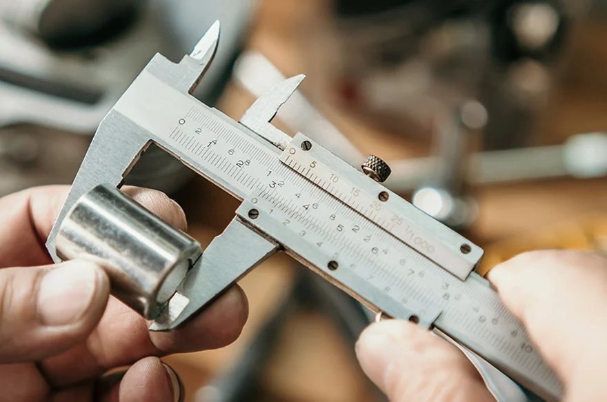
Specifying Tolerances and Surface Finishes
You've selected your material and prepared your files. Now comes the specification that most directly impacts both part function and manufacturing cost: tolerances. When you order CNC machined parts, the dimensional precision you specify tells manufacturers exactly how carefully they need to measure every cut—and that precision level drives machine time, inspection requirements, and ultimately your quote.
Here's what catches many buyers off guard: tolerance specification isn't just about picking a number. It's about understanding which dimensions actually matter for your application and communicating that intent clearly. Over-tolerancing wastes money on unnecessary precision. Under-tolerancing risks parts that don't fit or function correctly. Let's develop a practical framework for getting this balance right.
Standard vs Precision Tolerance Classes
Every CNC cutting operation introduces some dimensional variation. Raw material conditions, tool wear, thermal expansion, and machine rigidity all contribute to minor deviations from nominal dimensions. The question isn't whether variation exists—it's how much variation your application can accept.
Precision machining services typically work within three general tolerance classes:
- Standard tolerances (±0.005" / ±0.127mm): The default for most CNC metal and plastic operations. This range accommodates normal process variation without requiring special equipment or extended cycle times. According to industry benchmarks, CNC routing and laser cutting commonly achieve ±0.005" tolerances across various materials—roughly the thickness of a single sheet of paper.
- Precision tolerances (±0.001" / ±0.025mm): Required for mating surfaces, bearing fits, and functional interfaces. Achieving this level demands slower feed rates, finer finishing passes, and more rigorous in-process measurement. Expect significant cost increases—often 1.5 to 2 times standard pricing for affected features.
- Ultra-precision tolerances (±0.0005" / ±0.0127mm or tighter): Reserved for optical components, aerospace interfaces, and medical devices requiring exceptional accuracy. These specifications require specialized equipment, climate-controlled environments, and extensive inspection. Costs can exceed three times standard rates.
The practical reality? Most machining parts function perfectly well at standard tolerances. The ±0.005" range allows for reliable bolt patterns, adequate clearance fits, and functional assemblies without premium pricing. Reserve tighter callouts only for features that genuinely require them.
Critical Dimensions That Require Tight Tolerances
Not every dimension on your part deserves the same precision level. Experienced engineers distinguish between critical and non-critical features—and so should your tolerance callouts.
Features that typically warrant precision tolerances:
- Bearing bores and shaft diameters where interference or clearance fits matter
- Mating surfaces between assembled components
- Locating features like dowel holes that establish alignment
- Sealing surfaces where gaskets or O-rings must compress correctly
- Thread pitch diameters for high-strength fastener connections
Features that typically accept standard tolerances:
- Overall envelope dimensions with no functional interfaces
- Clearance holes for bolts (where the bolt is significantly smaller than the hole)
- Cosmetic surfaces not affecting assembly
- Internal pocket dimensions for weight reduction rather than fit
When preparing your order for precision machining parts, identify critical dimensions explicitly on your drawing. Use a note like "All dimensions ±0.005" unless otherwise specified" to establish your baseline, then call out tighter tolerances only where function demands them.
Understanding GD&T Basics for Ordering
Geometric Dimensioning and Tolerancing (GD&T) provides a standardized language for specifying not just size, but also form, orientation, and position. While mastering GD&T takes years, understanding three fundamental concepts helps you communicate requirements effectively:
Position tolerance controls where a feature (like a hole) is located relative to datum references. Rather than using coordinate tolerancing that creates a square tolerance zone, position tolerance defines a cylindrical zone—providing approximately 57% more usable area for the same numeric value. This becomes particularly important for bolt hole patterns where you need consistent spacing.
Flatness specifies how much a surface can deviate from a perfect plane. For precision machining services producing mating flanges or sealing surfaces, a flatness callout of 0.002" ensures the surface won't rock or leak regardless of what size tolerances allow.
Perpendicularity controls how square one feature is to another—critical for holes that must align through stacked plates or surfaces that mount against reference faces.
You don't need to become a GD&T expert to order parts effectively. However, if your application requires controlled relationships between features rather than just individual dimensions, consulting with your manufacturer about appropriate GD&T callouts prevents misunderstandings that cause functional failures.
Surface Finish Options and When to Specify Each
Surface finish affects both appearance and function. CNC cuts leave characteristic tool marks whose visibility and texture depend on cutting parameters and post-processing:
As-machined (Ra 125-250 μin): The default condition showing visible tool paths. Functional for most mechanical applications but may not meet cosmetic expectations. No additional cost.
Bead blasting: Creates a uniform matte texture that hides machining marks and minor surface defects. Popular for handling surfaces and prototypes where fingerprints would otherwise show. Adds modest cost and 1-2 days to lead time.
Anodizing (Type II or Type III): Electrochemical conversion creates a durable oxide layer on aluminum. Type II provides color options and corrosion resistance; Type III (hardcoat) adds significant wear resistance. Adds 2-5 days depending on color and specification. Note that anodizing adds 0.0002"-0.0009" per side—factor this into tolerance calculations for tight-fitting parts.
Powder coating: Applies durable color finishes to steel and aluminum. Excellent for housings and covers requiring specific colors. However, powder coating can add 0.002"-0.005" per side—significant for precision features. Mask critical surfaces or apply before final machining of mating interfaces.
Specify finishes based on function first, aesthetics second. A bearing bore needs tight tolerances and smooth finish; an exterior panel needs corrosion protection and color. Different requirements, different specifications.
How Tolerances Impact Your Quote
Understanding the cost relationship helps you specify tolerances strategically. The pricing impact follows a roughly exponential curve—each step tighter than standard roughly doubles the cost premium for affected features:
- Standard (±0.005"): Baseline pricing—no premium
- Precision (±0.001"): 1.5-2x premium on toleranced features
- High precision (±0.0005"): 2-3x premium, may require specialized equipment
- Ultra-precision (±0.0001"): 4x+ premium, limited manufacturer capability
Beyond direct machining costs, tight tolerances trigger additional expenses: incoming material inspection, in-process measurement, final CMM (coordinate measuring machine) verification, and documentation. For critical applications, you may need to request first-article inspection reports, capability studies, or certified dimensional reports—all adding cost but providing confidence in part conformance.
When communicating quality verification needs, specify exactly what documentation you require. Options include dimensional inspection reports (measurements of specified features), first-article inspection (comprehensive verification of initial production parts), and certificates of conformance (formal statements that parts meet drawing requirements). Request only what you need—over-specifying inspection adds cost without proportional value.
With tolerances and finishes defined, you now have the technical specifications manufacturers need. The next step involves understanding how these choices—along with material, quantity, and complexity—combine to determine what you'll pay for your precision machined parts.
Understanding CNC Machining Costs and Pricing
You've prepared your files, selected materials, and specified tolerances. Now comes the question every buyer asks: what will this actually cost? When you order CNC parts, pricing transparency often feels elusive—quotes vary dramatically between suppliers, and understanding why requires looking beneath the surface at how manufacturers calculate costs.
Here's the reality: CNC machining price isn't a single number pulled from a catalog. It's a calculated sum of machine time, material consumption, setup labor, and finishing operations. Understanding these components empowers you to make informed decisions, optimize designs for cost-effectiveness, and recognize when a quote accurately reflects your requirements.
Breaking Down CNC Pricing Components
Every CNC quote you receive reflects a straightforward formula, even when suppliers don't explicitly show their math:
Total Cost = (Machine Time × Hourly Rate) + Material Cost + Setup Cost + Finishing Cost + Shipping
Let's examine each component so you understand where your money goes:
Machine time and hourly rates typically represent the largest portion of your quote. According to industry data for 2025, standard 3-axis milling and turning operations run $70-$125 per hour, while 5-axis machining commands $150-$250 per hour due to equipment complexity and operator skill requirements. Your part's geometry directly determines how long it occupies the machine—every pocket, hole, and contoured surface adds cutting time.
Material cost includes both the raw stock price and inevitable waste. CNC machining is subtractive—you're buying a block larger than your finished part, and everything cut away still costs money. Aluminum typically runs $3-$8 per pound, stainless steel $8-$16, and titanium can exceed $30 per pound before machining begins.
Setup charges cover machine programming, fixture preparation, and first-article verification. This one-time cost remains relatively fixed regardless of quantity—which is why ordering ten parts costs far less per unit than ordering one. Complex parts requiring multiple setups or custom fixturing increase this component significantly.
Finishing operations add cost based on the processes specified. Bead blasting might add $5-$15 per part, while anodizing runs $25-$75 depending on type and batch size. Powder coating, plating, and specialized treatments each carry their own pricing structures.
The following table illustrates how complexity factors affect relative pricing when you order custom CNC machining services:
| Complexity Factor | Example | Cost Impact | Why It Costs More |
|---|---|---|---|
| Simple geometry | Rectangular bracket with holes | Baseline | Minimal tool changes, single setup |
| Moderate complexity | Pockets, contours, multiple features | +30-50% | Extended cycle time, more tool paths |
| Tight tolerances | ±0.001" on critical features | +50-100% | Slower feeds, finishing passes, inspection |
| Multi-axis requirements | Undercuts, compound angles | +75-150% | 5-axis machine rates, specialized programming |
| Difficult materials | Titanium, Inconel, hardened steel | +100-200% | Slow cutting speeds, rapid tool wear |
| Thin walls/fine features | Walls under 0.040", deep pockets | +40-80% | Reduced feeds, vibration management |
Strategies to Optimize Part Cost
Once you understand what drives pricing, you can make design and specification choices that reduce costs without sacrificing functionality. These strategies apply whether you're working with large CNC machining shops or small CNC machining operations:
Simplify geometry where function permits. Every feature requires programming, tool paths, and cutting time. Ask yourself: does this pocket need to be 2" deep, or would 1" accomplish the same purpose? Can sharp internal corners become radii that match standard end mill sizes? According to manufacturing cost studies, internal corners with radii at least 1/3 the pocket depth significantly reduce machining time by allowing larger, more rigid tools.
Specify standard tolerances except where function demands precision. Applying ±0.001" across an entire CNC machining part when only two features require that accuracy inflates costs unnecessarily. Use standard ±0.005" as your baseline and call out tighter tolerances only on critical mating surfaces or functional interfaces.
Consider material substitution. If your application allows, aluminum machines roughly 2-3 times faster than stainless steel at lower material cost. Before specifying an expensive alloy, verify that its properties are genuinely required—or whether a more machinable alternative meets your needs.
Consolidate finishing requirements. Multiple surface treatments add processing steps, handling time, and potential for damage between operations. If possible, design so a single finish type applies to the entire part rather than masking some areas for different treatments.
Avoid unnecessarily thin walls and deep cavities. Features requiring specialized tooling or reduced cutting speeds add disproportionate cost. Industry guidelines suggest keeping cavity depth no more than four times the width and maintaining wall thicknesses above 0.040" for metals.
Understanding Quantity Price Breaks
The difference between prototype pricing and production pricing often surprises first-time buyers. A single part might cost $150 while ten identical parts cost $40 each—same geometry, same material, dramatically different economics.
This happens because setup costs distribute across quantity. Consider a part with $200 in setup charges and $20 in per-unit machining cost:
- 1 part: $200 setup + $20 machining = $220 per unit
- 10 parts: $200 setup + $200 machining = $40 per unit
- 100 parts: $200 setup + $2,000 machining = $22 per unit
Minimum order quantities exist because some jobs simply aren't economical at very low volumes. The machinist metal cost and machine time for a single complex part might not cover the overhead of quoting, programming, and inspecting the work. Many shops establish minimums around $75-$150 to ensure orders remain viable.
When getting an online machining quote or CNC quote online, consider your true quantity needs. If you'll eventually need 50 parts, ordering all 50 now—rather than five orders of 10—reduces total cost substantially. Alternatively, some suppliers offer blanket orders that lock in production pricing across scheduled releases.
Getting Accurate Quotes Upfront
The most reliable way to receive accurate pricing? Provide complete specifications from the start. Incomplete information forces manufacturers to assume worst-case scenarios—or follow up with questions that delay your quote.
When requesting quotes, include:
- 3D model in STEP format with 2D drawing for toleranced features
- Material specification including grade and any certification requirements
- Quantity needed, including whether this is prototype or production intent
- Required tolerances clearly identified on critical features
- Surface finish and post-processing requirements
- Target delivery date or timeline flexibility
Vague requests generate vague quotes. The more precisely you define what you need, the more accurately manufacturers can price the work—and the fewer surprises you'll encounter when parts arrive.
With a clear understanding of how pricing works and strategies to optimize costs, you're ready to navigate the complete ordering workflow from initial quote request through final delivery.
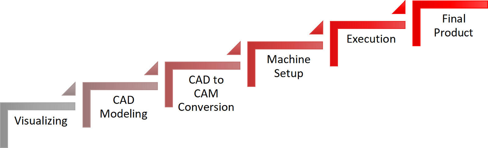
Navigating the Order Workflow from Quote to Delivery
You've prepared your files, selected materials, specified tolerances, and understand what drives pricing. Now comes the practical question: what actually happens after you click "submit"? When you order CNC parts, the process between uploading your design and receiving finished components involves multiple stages—each with opportunities to accelerate timelines or inadvertently cause delays.
Whether you're working with CNC machine shops near me or partnering with manufacturers across the globe, the fundamental workflow remains consistent. Understanding each step helps you set realistic expectations, communicate effectively, and avoid the common pitfalls that extend lead times.
The Quote-to-Delivery Timeline
Most buyers underestimate how much happens between quote approval and shipping. Here's the complete workflow you'll navigate:
- File upload and specification: You submit your 3D model, 2D drawings, and specify material, quantity, tolerances, and finish requirements. Complete submissions receive faster responses—missing information triggers clarification requests that add 1-2 days.
- Quote generation: The manufacturer reviews your files, calculates machine time, material costs, and finishing operations. Automated quoting systems can respond within hours; complex parts requiring manual review may take 1-3 business days.
- Design for Manufacturability (DFM) review: Engineers analyze your design for potential issues—features that are impossible to machine, unnecessarily expensive tolerances, or geometry that risks quality problems. You'll receive feedback with suggested modifications.
- Quote approval and order placement: You review the quote, accept any DFM recommendations, and authorize production. Payment terms vary—prototypes typically require upfront payment, while production orders may offer net terms for established customers.
- Production scheduling: Your order enters the queue based on current shop capacity and your requested timeline. Standard lead times depend on complexity and quantity.
- Machining operations: Raw material is prepared, fixtures are set, and your parts are cut according to the programmed toolpaths. Complex parts may require multiple setups across different machines.
- Quality inspection: Finished parts undergo dimensional verification against your specifications. Critical tolerance features receive individual measurement; standard parts may use sampling protocols.
- Finishing operations: If you specified surface treatments—bead blasting, anodizing, powder coating—parts route to those processes after machining inspection.
- Final inspection and packaging: Completed parts receive final quality verification, documentation preparation, and protective packaging for shipment.
- Shipping and delivery: Parts ship via your selected carrier. Tracking information allows you to monitor transit and plan for receiving.
According to industry workflow documentation, these steps—from quoting and ordering to DFM review, sourcing, and production—represent the standard path your order follows. Understanding this sequence helps you anticipate where delays might occur and how to prevent them.
What Happens After You Submit Your Order
Once you approve production, several factors determine how quickly parts move through the shop:
Part complexity: Simple brackets with basic holes might complete in 2-3 days of actual machining time. Multi-axis parts with tight tolerances, multiple setups, and extensive finishing can require 2-3 weeks of production activity. The difference isn't just machine time—it's programming, fixture preparation, inspection, and quality documentation.
Material availability: Standard aluminum and steel grades typically ship from distributors within 1-2 days. Specialty alloys, specific tempers, or certified materials may require 1-4 weeks for procurement before machining even begins. When searching for machining shops near me, confirm material availability before committing to timelines.
Quantity effects: Counterintuitively, larger quantities don't always mean proportionally longer lead times. Once setup is complete, additional parts flow relatively quickly. However, very large orders may exceed single-machine capacity, requiring scheduling across multiple shifts or machines.
Finishing requirements: Anodizing typically adds 2-5 business days depending on the provider's queue. Powder coating, plating, and specialty treatments may add 3-7 days. Heat treatment requirements can extend timelines by 1-2 weeks for external processing.
Current shop capacity: Even capable manufacturers have finite machine time. During peak seasons or when serving major production contracts, lead times extend. Local machine shops and larger CNC turning services alike experience capacity fluctuations—building relationships helps you receive priority when schedules tighten.
Realistic expectations prevent frustration. Standard prototype lead times run 5-10 business days for simple aluminum parts with basic finishes. Production orders typically quote 2-4 weeks depending on quantity and complexity. Specialty materials or demanding specifications can extend timelines to 6-8 weeks or longer.
Communicating with Your Manufacturing Partner
Effective communication separates smooth orders from frustrating experiences. As industry experts emphasize, collaborating closely with machine shop professionals helps optimize manufacturing designs and ensures the final product aligns with your needs.
Handling design revisions: Changes happen—prototyping often reveals needed modifications. However, revision timing matters enormously. Changes before production begins typically require only updated quotes and file replacements. Changes after machining starts may mean scrapped material, repeated setups, and significant additional costs. If you anticipate design iteration, consider ordering smaller prototype quantities first.
When revisions are necessary, communicate them through proper channels—not informal emails or phone calls that might not reach the production floor. Request acknowledgment that changes were received and confirm the impact on cost and timeline before authorizing continued work.
Proactive status updates: Don't wait until the delivery date passes to ask about your order. Establish check-in points when placing orders—confirmation of material receipt, notification when machining begins, and alert when parts ship. Professional CNC turning service providers typically offer online portals or email updates; smaller machinist shops near me might require phone follow-up.
Documentation expectations: Clarify what paperwork you'll receive with delivered parts. Inspection reports, material certifications, and certificates of conformance should be specified upfront. Requesting documentation after parts ship often causes delays and additional charges.
When Rush Orders Make Sense
Expedite options exist for genuine emergencies—but they come at a premium:
- Rush fees: Expect 1.5-2x standard pricing for expedited production. The shop is disrupting scheduled work to prioritize yours.
- Overtime charges: Weekend or overnight production may require additional labor premiums.
- Express shipping: Air freight for parts that would normally ship ground adds significant cost, especially for heavier components.
Rush orders make sense when downtime costs exceed expedite fees—a production line waiting on parts, a trade show deadline, or customer commitments that can't be rescheduled. They don't make sense for poor planning. Consistently rushing orders strains supplier relationships and drains budget that could fund additional engineering or better materials.
The smarter approach? Build realistic timelines from the start. Add buffer for unexpected issues. Develop relationships with reliable suppliers—whether a cnc shop near me or a specialized manufacturer—who understand your quality requirements and can deliver consistently.
With the complete ordering workflow understood, you're prepared to evaluate whether CNC machining is the right choice for your application—or whether alternative manufacturing methods might better serve your specific needs.
Choosing CNC Over Alternative Manufacturing Methods
You've learned how to prepare files, select materials, specify tolerances, and navigate the ordering workflow. But here's a question worth asking before you submit that order: is CNC machining actually the right process for your application? When you order CNC parts, you're choosing one manufacturing method among several—and understanding when alternatives make more sense can save significant time and money.
The reality is that no single manufacturing process excels at everything. CNC machining delivers exceptional precision and material versatility, but 3D printing offers geometric freedom that subtractive methods can't match. Injection molding dominates high-volume production economics. Sheet metal fabrication handles enclosures efficiently. The key is matching your specific requirements—quantity, precision, material, timeline—to the process best suited for them.
CNC vs 3D Printing Decision Framework
These two technologies overlap more than you might expect, particularly for prototyping and functional parts. Both can produce complex geometries in plastics and metals. Both work from digital files. So when does each make sense?
According to manufacturing technology research, CNC machining generally outperforms 3D printing when dimensional accuracy is a top priority. CNC offers high precision, excellent repeatability, and tight tolerances across part sizes ranging from micro-scale components to large structural assemblies. The mechanical properties remain consistent and isotropic—strength is the same in all directions.
3D printing becomes the better choice under specific conditions:
- Complex geometries: Parts with intricate internal channels, lattice structures, or topology-optimized features that cutting tools simply cannot reach
- Rapid turnaround: When you need functional prototypes within 24-48 hours rather than 5-10 days
- Lower quantities: For quantities under 10 units, additive manufacturing typically costs less than CNC due to minimal setup requirements
- Specialty materials: Flexible TPU, high-performance superalloys, or experimental composites that are difficult or impossible to machine
For prototype machining applications where you need to validate both form and function, consider your priorities. If mechanical performance under load matters—strength, thermal resistance, fatigue life—CNC delivers superior results. If you're testing ergonomics, fit, or visual appearance before committing to production tooling, 3D printing's speed advantage often outweighs its material limitations.
Carbon fiber prototyping presents an interesting case. While 3D printing can produce carbon fiber-reinforced parts, CNC machining of carbon fiber composites yields stronger, more dimensionally stable components—though at higher cost and with specialized tooling requirements.
When Injection Molding Makes More Sense
Here's a threshold that surprises many first-time buyers: somewhere between 500 and 1,000 identical plastic parts, injection molding typically becomes more cost-effective than CNC machining. The exact crossover depends on part complexity, material, and tolerance requirements—but the economic shift is dramatic.
Injection molding requires significant upfront investment in tooling—$5,000 to $50,000+ depending on complexity. However, once that mold exists, per-part costs drop to dollars or even cents. CNC machining carries no tooling investment but maintains relatively fixed per-part costs regardless of quantity.
As industry comparisons note, injection molding is ideal for high-volume production and complex geometries with detailed features, offering consistency and repeatability that makes it particularly attractive across multiple industries. CNC machining remains preferable when you need tight tolerances, complex shapes, or low-to-medium quantities in metals or engineering plastics.
The decision framework becomes clearer when you consider your production trajectory. For products still evolving through design iterations, CNC's flexibility—no tooling to modify—keeps development costs manageable. Once designs stabilize and volumes justify tooling investment, transitioning to injection molding optimizes long-term economics.
Manufacturing Method Comparison
The following table summarizes key decision factors across common manufacturing methods. Use it to quickly identify which processes align with your specific requirements:
| Factor | CNC Machining | 3D Printing | Injection Molding | Sheet Metal |
|---|---|---|---|---|
| Ideal Quantity | 1-500 parts | 1-50 parts | 500+ parts | 10-10,000 parts |
| Material Options | Metals, plastics, composites | Plastics, some metals | Thermoplastics primarily | Metals only |
| Precision Capability | ±0.001" achievable | ±0.005" typical | ±0.003" typical | ±0.010" typical |
| Lead Time | 5-15 days | 1-5 days | 4-8 weeks (with tooling) | 5-10 days |
| Cost Structure | Moderate setup, moderate per-part | No setup, higher per-part | High tooling, very low per-part | Low-moderate setup, low per-part |
| Geometry Freedom | Limited by tool access | Nearly unlimited | Moderate (draft angles required) | Limited to bends/forms |
Notice how CNC machining occupies a middle ground—versatile enough for prototypes yet capable of production quantities, precise enough for critical components yet cost-effective for functional parts. This versatility explains why it remains the default choice for custom metal and plastic components across industries.
For specialized applications, CNC routing and CNC wood routing serve distinct markets. Wood CNC operations excel at signage, furniture components, and decorative elements where the natural material properties matter. Router wood CNC systems handle larger sheet goods efficiently, though precision capabilities differ from metal-focused machining centers.
Hybrid Manufacturing Approaches
Here's what experienced engineers know: you don't have to choose just one process. Combining manufacturing methods often delivers better results than any single approach.
3D printed prototypes before CNC production: Print initial prototypes quickly and inexpensively to validate form, fit, and basic function. Once the design stabilizes, order CNC parts for performance testing and final validation. This sequence minimizes expensive machining iterations while ensuring production parts meet mechanical requirements.
CNC machined mold inserts for injection molding: Rather than investing in full production tooling upfront, some manufacturers offer aluminum molds machined via CNC for bridge production—100 to 10,000 parts while steel production tooling is manufactured.
Hybrid metal parts: As manufacturing guides suggest, a hybrid approach can offer the best of both worlds: 3D print the complex core of a component, then CNC machine critical features like mounting holes and sealing surfaces to achieve precise tolerances. This balances design complexity with functional performance.
According to industry expertise, CNC machining eliminates the need for dedicated tooling, making it ideal for prototyping, product development, and small-batch runs. In early-stage product development where designs often evolve, CNC offers unmatched flexibility to adapt without incurring significant retooling costs.
Your ordering strategy should evolve with your product lifecycle. Early development favors rapid, flexible methods like 3D printing. Functional validation demands CNC's precision and material authenticity. Scale production shifts economics toward injection molding or other high-volume processes. Understanding this progression helps you invest appropriately at each stage.
With a clear framework for when CNC machining serves your needs best—and when alternatives might be more appropriate—you're ready to consider one more critical factor: the industry-specific certifications and quality requirements that may apply to your application.
Industry Certifications and Quality Requirements
You've selected your manufacturing method, prepared your files, and understand the ordering workflow. But depending on your industry, there's one more critical consideration before placing that order: certifications. When you order CNC parts for regulated sectors like aerospace, automotive, or medical devices, the manufacturer's quality credentials aren't just nice-to-have credentials—they're often contractual requirements that determine whether you can use those parts at all.
Here's what catches many buyers off guard: certification requirements flow down from your customers and regulatory bodies, not up from your preferences. If you're supplying components to an automotive OEM, they'll specify IATF 16949 compliance. Aerospace primes mandate AS9100. Medical device companies require ISO 13485. Understanding these requirements before you order prevents costly delays when parts arrive without the documentation your quality team—or your customer—demands.
Certification Requirements by Industry
Different sectors have established distinct quality management standards based on the consequences of component failure. The more critical the application, the more rigorous the certification requirements.
General manufacturing (ISO 9001): This internationally recognized standard serves as the foundation for quality management systems across industries. According to industry research, ISO 9001 provides the structural framework to document and control workflows, trace nonconformances, implement corrective actions, and drive continuous improvement. When working with any CNC machining shop, ISO 9001 certification signals that documented quality control processes exist—think of it as the baseline credential for professional manufacturing.
Automotive (IATF 16949): This standard builds upon ISO 9001 with automotive-specific requirements for defect prevention, statistical process control, and supply chain management. If you're ordering parts for automotive applications, IATF 16949 certification is typically non-negotiable. The standard emphasizes Production Part Approval Process (PPAP) documentation, which validates that your supplier can consistently reproduce parts meeting your specifications. Precision machining companies serving automotive markets maintain these certifications specifically because OEMs require them for supplier qualification.
Aerospace (AS9100D): Aerospace CNC machining operates under the most stringent quality requirements in manufacturing. AS9100 extends ISO 9001 with enhanced risk management, configuration control, and traceability protocols. As certification guides explain, AS9100-certified facilities must maintain auditable process documentation, meticulous part verification, and complete material traceability from billet to finished component. For 5 axis CNC machining services producing complex aerospace geometries, this certification validates capability to meet demands where failure is not an option.
Medical devices (ISO 13485): Medical machining requires specialized quality controls focused on patient safety. ISO 13485 mandates detailed documentation practices, thorough quality checks, risk mitigation procedures, and effective complaint handling systems. Swiss machining operations producing surgical instruments or implantable components must demonstrate compliance with this standard to satisfy FDA and international regulatory requirements.
Defense (ITAR compliance): Beyond quality management certifications, defense-related CNC work falls under International Traffic in Arms Regulations. ITAR compliance requires registration with the U.S. Department of State and stringent information security protocols for handling sensitive technical data and controlled components.
Quality Documentation You May Need to Request
Certifications validate a manufacturer's quality system, but specific orders require specific documentation. When placing orders for precision CNC machining services, clarify upfront what paperwork you'll need with delivered parts:
- Dimensional inspection reports: Measurements of specified features verified against your drawing tolerances, typically generated using coordinate measuring machines (CMMs) or calibrated inspection tools
- First Article Inspection (FAI) reports: Comprehensive verification of initial production parts against all drawing requirements—often required for aerospace applications using AS9102 formats
- Material certifications (mill certs): Documentation from the material supplier verifying chemical composition, mechanical properties, and heat lot traceability
- Certificates of Conformance (CoC): Formal statements that parts were manufactured according to your specifications and meet all stated requirements
- Process certifications: Documentation for special processes like heat treatment, plating, or non-destructive testing performed by qualified suppliers
- PPAP packages: For automotive applications, complete Production Part Approval Process documentation including control plans, process flow diagrams, and capability studies
Not every order requires every document. Prototype work for internal testing rarely needs material certifications. Production components for regulated industries typically require complete documentation packages. Specify your requirements when requesting quotes—documentation adds cost, and manufacturers quote accordingly.
Traceability Requirements and How to Specify Them
Traceability connects finished parts back through every step of their creation—material source, machining operations, operator identification, inspection results, and shipping records. For critical applications, this chain of documentation enables root cause analysis if problems emerge and demonstrates due diligence for regulatory compliance.
When traceability matters for your application, specify requirements clearly:
Material lot traceability: Request that your parts be manufactured from a single material lot with documentation linking finished components to the original mill certificate. This proves consistent material properties across your order.
Serial number marking: For individual part tracking, specify permanent marking requirements—engraving, laser marking, or ink stamping—with your preferred serialization scheme.
Process documentation retention: Clarify how long the manufacturer must retain production records. Aerospace and medical applications often require 7-10 years of documentation retention.
Batch segregation: If you need to track parts by production date or shift, specify batch identification requirements that keep production groups distinguishable.
The level of traceability you specify should match your application's criticality. Over-specifying adds cost without value; under-specifying leaves gaps when quality issues arise. For general commercial parts, standard shop documentation typically suffices. For safety-critical components, full traceability from raw material through final inspection provides necessary assurance.
Working with Certified Manufacturing Partners
Finding a CNC machining shop with the right certifications for your industry simplifies ordering significantly. Rather than educating suppliers on your quality requirements, certified partners already understand what documentation you need, what inspection protocols apply, and how to package deliverables for your quality system.
For automotive applications specifically, IATF 16949-certified facilities like Shaoyi Metal Technology provide the quality assurance automotive buyers require. Their Statistical Process Control (SPC) systems ensure consistent high-tolerance components across production runs—exactly what automotive supply chains demand for reliable performance.
When evaluating potential manufacturing partners, verify certifications directly. Request certificate copies showing current validity dates and certification body information. Confirm that certifications cover the specific processes you need—a facility certified for turning might not hold certifications for multi-axis milling or specialized finishing operations.
According to supplier qualification research, certifications act like a safety net, giving you confidence that your supplier's processes are audited and reliable. They're your first line of defense against poor quality, late deliveries, and compliance headaches.
The investment in finding properly certified precision machining companies pays dividends throughout your relationship. Certified partners understand controlled documentation, maintain calibrated inspection equipment, and train personnel to quality-focused standards. These capabilities translate directly to parts that meet specifications consistently—reducing incoming inspection burden, minimizing rejects, and keeping your production schedules on track.
With certification requirements understood and quality documentation specified, you're prepared to put all your CNC ordering knowledge into action—transforming from a first-time buyer into a confident manufacturing partner who knows exactly what to ask for and what to expect.
Putting Your CNC Order Knowledge into Action
You've traveled the complete journey from understanding file formats to navigating certification requirements. Now comes the moment that matters: placing your first order with confidence—or optimizing your next one based on everything you've learned. When you order CNC parts successfully, the difference between frustration and satisfaction comes down to preparation, communication, and partnership.
Here's what separates experienced buyers from first-timers: they approach ordering as a collaborative process rather than a transaction. They provide complete information upfront, ask clarifying questions before production begins, and build relationships with manufacturing partners who understand their evolving needs. That's the approach this guide has prepared you to take.
Your Pre-Order Checklist
Before clicking submit on your next quote request, run through this comprehensive checklist. Each item represents a potential delay or cost escalation if overlooked—and a smooth production experience when addressed properly:
- File preparation complete: 3D model exported as STEP format with watertight geometry, proper units verified, and coordinate system aligned with intended fixturing orientation
- 2D drawing included: Technical drawing with toleranced dimensions, GD&T callouts for critical features, surface finish specifications, and complete title block information
- Material fully specified: Exact grade designation (not just "aluminum" but "6061-T6"), any certification requirements noted, and finish condition specified
- Tolerances appropriately assigned: Standard tolerances as baseline with precision callouts only on functionally critical features—avoiding over-tolerancing that inflates costs
- Quantity confirmed: Total parts needed including any spares, with indication of whether this represents prototype or production intent
- Surface finish defined: As-machined acceptable or specific treatments required (bead blast, anodize type and color, powder coat specification)
- Quality documentation specified: Inspection reports, material certifications, certificates of conformance, or PPAP requirements clearly listed
- Timeline expectations realistic: Required delivery date with understanding of standard lead times for your part complexity and finishing requirements
- Contact information current: Technical contact for DFM questions, shipping address verified, and any special receiving instructions noted
This checklist isn't bureaucratic overhead—it's the difference between a quote that accurately reflects your needs and one that requires multiple revision cycles. According to sourcing research, clear communication of tolerances and specifications helps minimize discrepancies during production and prevents costly rework.
Building Long-Term Manufacturing Relationships
Imagine searching for "cnc machining near me" or "cnc shops near me" every time you need parts. You'd spend hours vetting new suppliers, explaining your quality requirements, and hoping they deliver as promised. That's the transactional approach—and it's exhausting.
The alternative? Find a reliable manufacturing partner who understands your industry, learns your specifications, and scales with your needs from prototyping through production. As industry experts emphasize, a contract manufacturer goes beyond the service of a regular supply chain vendor to create a true partnership invested in your success.
What makes a manufacturing relationship valuable over time?
Institutional knowledge: Partners who've produced your parts before understand your tolerances, materials, and quality expectations. They catch potential issues before quoting rather than discovering problems mid-production.
Scalability: The right partner handles your prototype order of five parts this month and your production run of five hundred next quarter—using consistent processes that maintain quality as volumes grow. According to manufacturing transition research, working with an experienced partner from the outset offers a streamlined path for parts procurement through the product development process and helps mitigate risk down the road.
Responsive communication: When design changes arise or timelines shift, established relationships mean faster responses and greater flexibility. Your project manager knows your history and prioritizes accordingly.
Quality consistency: Partners invested in long-term relationships maintain rigorous quality standards because they understand that one bad shipment damages years of built trust. They're not cutting corners to win a single order.
Whether you find that partner by searching "machinist near me" for local CNC service providers or by qualifying specialized manufacturers for your industry, the goal remains the same: transform ordering from a repeated evaluation process into a predictable, reliable supply chain element.
Taking the Next Step
You now understand what most first-time buyers learn through trial and error: successful CNC ordering requires more than uploading a file and waiting for parts. It demands complete file preparation, clear tolerance specification, appropriate material selection, and realistic timeline expectations. It benefits from understanding how pricing works, when alternative manufacturing methods make sense, and what certifications your industry requires.
This educational approach—becoming an informed buyer rather than a passive customer—delivers tangible results. You'll receive accurate quotes faster because your specifications are complete. You'll avoid revision cycles because your files are manufacturing-ready. You'll build supplier relationships because partners appreciate working with prepared customers who understand the process.
For readers seeking a certified manufacturing partner capable of handling demanding applications, precision CNC machining services with fast lead times—as quick as one working day—and capabilities spanning complex chassis assemblies to custom machine metal bushings can accelerate supply chain needs significantly. Explore automotive machining solutions from IATF 16949-certified facilities that combine Statistical Process Control with rapid turnaround, whether you need CNC parts for prototyping or production volumes.
The CNC ordering process doesn't have to be intimidating. Armed with the knowledge from this guide, you're prepared to specify requirements confidently, communicate effectively with manufacturers, and receive CNC service that matches your expectations. Your next order—whether searching for "cnc near me" or partnering with specialized global suppliers—starts with the preparation you've now completed.
Ready to put your knowledge into action? Gather your design files, complete the pre-order checklist, and take the first step toward manufacturing partnership rather than simple procurement. The difference between hoping for good results and expecting them comes down to the preparation you bring to every order.
Frequently Asked Questions About Ordering CNC Parts
1. What file format is best for CNC machining orders?
STEP (.step or .stp) is the gold standard for CNC orders. It captures exact NURBS geometry and topological information including faces, edges, and surfaces that create true solid models. While IGES and native CAD formats work, STEP AP214 offers the best mathematical precision and universal compatibility across CAM software systems, reducing file interpretation errors that delay production.
2. How much does CNC machining cost?
CNC machining costs depend on machine time ($70-$250/hour depending on 3-axis vs 5-axis), material costs, setup charges, and finishing operations. A simple aluminum bracket might cost $50-$150 for a single prototype, while complex parts with tight tolerances can exceed $500. Quantity significantly affects per-unit pricing—setup costs distribute across more parts, so ordering 10 units typically costs 70-80% less per part than ordering one.
3. What is the typical lead time for CNC machined parts?
Standard prototype lead times run 5-10 business days for simple aluminum parts with basic finishes. Production orders typically quote 2-4 weeks depending on quantity and complexity. Factors affecting timeline include part complexity, material availability (specialty alloys may require 1-4 weeks procurement), finishing requirements (anodizing adds 2-5 days), and current shop capacity. Rush orders can reduce timelines to 1-3 days at premium pricing.
4. What tolerances can CNC machining achieve?
CNC machining offers three general tolerance classes: standard (±0.005"/±0.127mm) for most applications, precision (±0.001"/±0.025mm) for mating surfaces and bearing fits, and ultra-precision (±0.0005" or tighter) for optical and aerospace components. Standard tolerances work for 90% of applications without cost premiums. Tighter tolerances increase costs 1.5-3x due to slower feeds, finishing passes, and rigorous inspection requirements.
5. How do I choose between CNC machining and 3D printing?
Choose CNC machining when you need superior dimensional accuracy, consistent mechanical properties, production-grade materials (metals or engineering plastics), or quantities above 10-50 units. Select 3D printing for complex internal geometries impossible to machine, rapid 24-48 hour turnaround, quantities under 10 units, or when testing form and fit before committing to production. Many projects benefit from hybrid approaches—3D print prototypes for validation, then CNC machine production parts.