 Small batches, high standards. Our rapid prototyping service makes validation faster and easier —

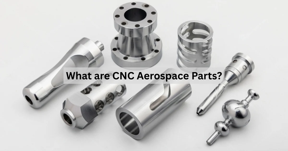
CNC Custom Machining Demystified: From First Quote To Finished Part
Understanding CNC Custom Machining and Why It Matters
Ever wondered how engineers transform digital designs into precision metal or plastic components? The answer often lies in CNC custom machining—a manufacturing process that creates parts built exactly to your unique specifications rather than pulled from a catalog of standard options.
CNC stands for Computer Numerical Control. Unlike traditional manual machining, where skilled operators guide cutting tools by hand, a CNC cutting machine follows precise computer-generated instructions to shape raw materials. According to Zintilon, this approach eliminates human error and delivers unfailing accuracy because the machine precisely follows programmed instructions for each cycle.
So what does "custom" really mean here? Simply put, you're not limited to off-the-shelf components. Whether you need a one-of-a-kind prototype or thousands of identical machined parts, every dimension, feature, and tolerance matches your exact design requirements.
Before exploring the workflow, let's look at what makes up a CNC system:
- Controller (MCU): The brain of the machine that reads G-code instructions and translates them into precise movements
- Machine Tool: The cutting equipment—mills, lathes, or routers—that physically shapes the material
- Workpiece: Your raw material block (metal, plastic, or wood) that gets transformed into the finished part
- Cutting Tools: End mills, drills, and turning tools that remove material to create your design
From Digital Design to Physical Reality
The journey from concept to finished component follows a clear path. It starts with a CAD (Computer-Aided Design) file—think of this as your digital blueprint. Designers sculpt every detail on screen: dimensions, curves, holes, and angles.
But here's the thing: CNC machines don't understand CAD files directly. They need a translation step. CAM (Computer-Aided Manufacturing) software converts your design into G-code—the step-by-step "recipe" the machine follows. This code controls everything from spindle speed to feed rate to exact toolpaths.
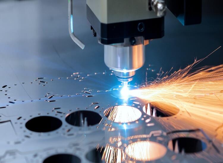
Once the machine is set up with your material secured and cutting tools loaded, the cnc cutting process begins. The machine spins tools at high speeds, moves them along programmed paths, and removes tiny chips of material until your part emerges. As zone3Dplus notes, this automated process delivers precision within ±0.01 mm—making it ideal for demanding applications.
Why Custom Beats Standard Components
Why invest in custom manufacturing when catalogs offer ready-made parts? The answer comes down to fit, function, and performance.
Standard components force you to design around their limitations. Custom machining flips that equation—your design drives the manufacturing, not the other way around. Need a bracket with non-standard hole spacing? A housing that fits your exact electronics layout? CNC turning or milling delivers precisely what you specify.
There's also the question of what is cnc routing and when it applies. CNC routing handles large-format work—think sheet materials and wood applications—while milling and turning excel at metal components requiring tighter tolerances.
The real difference between CNC and manual machining? Repeatability. Traditional methods depend entirely on operator skill, introducing variations between parts. CNC machines produce thousands of identical components because they follow the same programmed instructions every single time. For production runs requiring consistency, that difference matters.
Choosing the Right CNC Machining Method for Your Project
Now that you understand how CNC custom machining works, the next question becomes: which method fits your project? Should your component be milled or turned? Is a router the better choice for your material? Making the wrong selection can lead to costly delays, tolerance issues, or unnecessary spending.
Think of it this way—each CNC process excels at specific tasks. Some handle flat, complex geometries brilliantly. Others specialize in cylindrical shapes or large sheet materials. Let's break down the major methods so you can match your project requirements to the right technology.
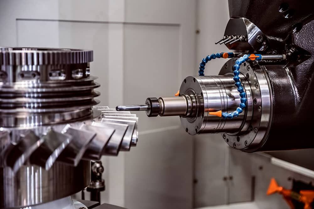
CNC Milling Explained
In CNC milling, the workpiece stays fixed while a rotating cutting tool moves across it, removing material layer by layer. Imagine peeling an apple with a spinning blade that travels in multiple directions—that's essentially what's happening.
This process shines when you need parts with flat surfaces, pockets, slots, or complex three-dimensional contours. According to RapidDirect, CNC milling handles challenging materials like steel, titanium, aluminum, and engineering plastics with exceptional precision.
But here's where it gets interesting—not all milling machines are created equal:
3-Axis Milling: The tool moves along three linear directions (X, Y, and Z). This setup handles straightforward tasks like drilling, pocketing, and facing. It's widely available, affordable, and perfect for parts without undercuts or complex angles. However, you'll need to reposition the workpiece to machine different faces, which adds time and potential for alignment errors.
5-Axis Milling: The tool or worktable can also tilt and rotate, adding two more degrees of movement. This means accessing virtually any angle without repositioning the part. The result? Fewer setups, better surface finishes on contoured surfaces, and the ability to machine features that 3-axis simply cannot reach. Aerospace components, turbine blades, and complex medical implants often require this capability.
When does 5-axis justify its higher cost? Consider it when your design includes deep cavities, undercuts, compound angles, or surfaces requiring continuous smooth tool contact. For simpler prismatic parts, 3-axis milling delivers excellent results at lower expense.
CNC Turning for Cylindrical Parts
CNC turning flips the script—here, the workpiece spins while a stationary cutting tool shapes it. Picture a potter's wheel, except the clay is metal and the shaping tool follows computer-controlled precision paths.
This method dominates when producing rotationally symmetric components: shafts, rods, bushings, pins, and tubes. As JLCCNC notes, CNC turning offers unmatched precision and efficiency for parts requiring precise diameter and length specifications.
Why choose cnc turning services over milling for cylindrical work? Speed and cost. Turning removes material faster from round stock, and the simpler tool movements mean shorter cycle times. For high-volume production of symmetrical parts, turning typically costs less per piece than milling the same geometry.
The limitation? Turning struggles with non-cylindrical features. Flat faces, pockets, or asymmetric shapes require either secondary milling operations or a mill-turn machine that combines both capabilities.
CNC Routing for Large-Format Work
What about projects involving sheet materials, wood, or large panels? That's where cnc routing enters the picture.
A CNC router uses a high-speed spindle to cut softer materials quickly across large work areas. Think signage, cabinet components, foam prototypes, and architectural elements. The wood cnc applications alone span furniture manufacturing, musical instruments, and decorative millwork.
Compared to milling machines, routers offer several advantages for appropriate applications. They're faster when cutting softer materials, more affordable to purchase and operate, and easier to set up for sheet goods. Cnc wood routing has transformed woodworking industries by enabling complex shapes that would take hours to produce by hand.
However, routers trade precision for speed. Their lighter frames generate more vibration, making them unsuitable for tight-tolerance metal work. When your project involves hard materials or requires tolerances under ±0.005", milling remains the better choice.
Comparing CNC Machining Methods at a Glance
Still unsure which process fits your project? This comparison table breaks down the key differences:
| Factor | CNC Milling | CNC Turning | CNC Routing | EDM |
|---|---|---|---|---|
| Typical Materials | Metals, plastics, composites | Metals, plastics | Wood, plastics, foam, soft metals | Conductive metals only |
| Part Geometries | Complex 3D shapes, pockets, slots, contours | Cylindrical, rotationally symmetric | Large flat panels, 2.5D profiles | Intricate details, sharp internal corners |
| Tolerance Capability | ±0.001" to ±0.005" | ±0.001" to ±0.005" | ±0.005" to ±0.010" | ±0.0001" to ±0.001" |
| Surface Finish Quality | Excellent (Ra 0.8-3.2 μm) | Excellent (Ra 0.4-3.2 μm) | Good (Ra 3.2-6.3 μm) | Mirror finish possible |
| Ideal Applications | Enclosures, brackets, molds, aerospace parts | Shafts, pins, bushings, fittings | Signs, cabinets, router wood cnc projects, prototypes | Dies, molds, hardened steel tooling |
| Relative Speed | Moderate | Fast for round parts | Very fast for soft materials | Slow |
| Cost Efficiency | Best for complex metal parts | Most economical for cylindrical parts | Lowest cost for cnc wood and sheet goods | Highest cost, specialized use |
Making Your Selection
Here's a practical approach to choosing the right method:
- Start with geometry: Cylindrical parts point toward turning. Complex 3D shapes or flat surfaces with features suggest milling. Large sheet materials or soft substrates favor routing.
- Consider your material: Hard metals require milling or turning. Softer materials like plastics, wood, or foam work well with routing.
- Check tolerance requirements: Ultra-tight specifications (under ±0.001") may require EDM or precision grinding. Standard industrial tolerances suit milling and turning.
- Factor in volume: High-volume cylindrical parts benefit from turning's speed. Complex cnc milled components may justify 5-axis investment for reduced setup time.
With the machining method selected, your next decision involves materials—and that choice impacts everything from cost to performance. Let's explore how to match materials to your application requirements.
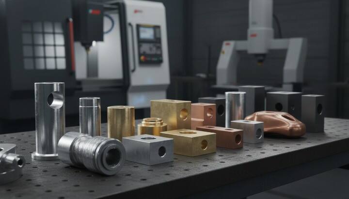
Material Selection Guide for CNC Custom Parts
You've chosen your machining method—now comes an equally critical decision: what material should your part be made from? This choice directly affects performance, cost, machinability, and longevity. Get it wrong, and you're looking at premature failures or budget overruns. Get it right, and your component delivers exactly what your application demands.
The good news? CNC machining handles virtually any metal or plastic. According to Hubs, the process works with such a wide range of materials that selecting the optimal one for your application can be quite challenging. Let's simplify that decision with a practical framework.
Metals for Strength and Durability
When your application demands high strength, hardness, or thermal resistance, metals are the answer. But which metal? Each alloy family offers distinct advantages.
Aluminum Alloys: These remain the workhorses of CNC custom machining. With an excellent strength-to-weight ratio, high thermal conductivity, and natural corrosion resistance, aluminum suits countless applications. It's also among the easiest metals to machine, which keeps costs down.
- 6061: The most common general-purpose aluminum—affordable, machinable, and versatile
- 7075: Aerospace-grade aluminum with fatigue properties comparable to steel when heat-treated
- 5083: Exceptional seawater resistance for marine and construction applications
Stainless Steel Alloys: Need corrosion resistance alongside strength? Stainless steel delivers. These alloys weld easily, polish beautifully, and resist wear.
- 304: The most widely used stainless steel—handles most environmental conditions
- 316: Superior chemical resistance, especially against saline solutions
- 17-4: Can be hardened to levels comparable to tool steels for high-performance applications
Bronze Alloys: When wear resistance and low friction matter, cnc bronze components excel. Machining bronze produces bearings, bushings, and gears that outlast alternatives in high-load applications. The material's natural lubricity means parts glide smoothly against mating surfaces. If you need to machine bronze for marine hardware or industrial equipment, expect excellent corrosion resistance and long service life.
Cnc machining bronze requires attention to chip formation and tool selection, but experienced shops handle it routinely. The resulting parts justify the material cost through extended operational life.
Engineering Plastics for Lightweight Solutions
Plastics aren't just cheaper alternatives to metals—they solve problems metals cannot. Lower weight, electrical insulation, chemical resistance, and self-lubricating properties make engineering plastics indispensable for specific applications.
Delrin (POM): This delrin plastic ranks as the most machinable thermoplastic available. It offers high stiffness, low friction, excellent dimensional stability at elevated temperatures, and minimal water absorption. When precision and tight tolerances matter in plastic components, Delrin is often the first choice.
Nylon (Polyamide): Excellent mechanical properties combined with outstanding impact strength and abrasion resistance make nylon for machining a popular option. The material handles chemical exposure well but absorbs moisture over time—a factor to consider for dimensional stability in humid environments.
Polycarbonate: Need transparency combined with toughness? Polycarbonate delivers impact strength superior to ABS while remaining machinable. Applications range from protective covers to fluidic devices.
Acrylic: For optical clarity and aesthetic applications, acrylic cnc machining produces everything from display cases to light guides. The material machines cleanly but requires care to prevent cracking.
As Rally Precision notes, plastics typically offer lower material and machining costs compared to metals. They're faster to machine, extend tool life, and require less aggressive cutting parameters.
Matching Materials to Application Requirements
How do you narrow down the options? Start with your application's non-negotiables, then balance secondary factors against cost.
| Material Category | Machinability | Strength-to-Weight | Corrosion Resistance | Relative Cost | Common Applications |
|---|---|---|---|---|---|
| Aluminum 6061 | Excellent | High | Good (anodizable) | Low | Prototypes, enclosures, brackets |
| Aluminum 7075 | Good | Very High | Moderate | Medium | Aerospace structures, high-stress components |
| Stainless Steel 304 | Moderate | Moderate | Excellent | Medium | Food equipment, medical devices |
| Bronze CNC | Good | Low | Excellent (marine) | Medium-High | Bearings, bushings, marine hardware |
| Delrin (POM) | Excellent | Very High (for plastic) | Excellent | Low | Gears, precision components, insulators |
| Nylon | Good | High (for plastic) | Good | Low | Wear parts, bushings, low-friction applications |
| Polycarbonate | Good | High (for plastic) | Good | Low-Medium | Protective covers, transparent housings |
Here's a practical decision path:
- Weight-critical aerospace or automotive parts? Start with aluminum 7075 for metal or PEEK for plastic alternatives
- Wear surfaces requiring low friction? Consider bronze cnc machining for heavy loads or nylon for lighter-duty applications
- Chemical or corrosive environments? Stainless steel 316 or PTFE handle aggressive media
- Tight budgets with moderate requirements? Aluminum 6061 for metals, Delrin for plastics
Material selection sets the foundation—but even the perfect material won't save a poorly designed part. Next, we'll explore Design for Manufacturability principles that help you avoid costly mistakes before production begins.
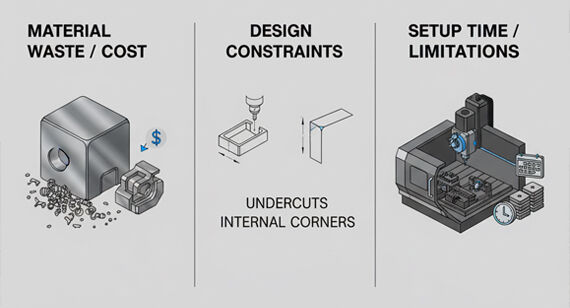
Design for Manufacturability Principles That Save Time and Money
You've selected your machining method and material—but here's the thing: how you design your part determines whether production runs smoothly or grinds to a costly halt. According to Frigate, nearly 20% of CNC production issues stem directly from drawing misinterpretations or oversights. Even worse, up to 30% of total machining costs often trace back to preventable design mistakes.
Design for Manufacturability (DFM) isn't about limiting creativity—it's about understanding what CNC machines can realistically achieve. When you design with machining in mind, you'll accelerate production time, reduce costs, and get better parts. Let's walk through the principles that separate smooth cnc prototyping runs from expensive headaches.
Wall Thickness and Feature Depth Rules
Imagine trying to machine a paper-thin wall—the cutting forces would bend or break it before you finish. That's why minimum wall thickness matters so much in CNC custom work.
Different materials handle thin features differently:
- Metals (aluminum, steel): Maintain at least 0.5mm (0.020") wall thickness for stability during primary machining operations
- Plastics (Delrin, nylon): Keep walls at 1.0mm (0.040") minimum—plastics flex more under cutting pressure
- Soft materials (wood, foam): A cnc wood cutter can handle thinner sections, but 2.0mm provides safer margins for detailed work
Feature depth follows similar logic. Deep, narrow pockets cause problems because extended tools deflect under cutting forces. As Protolabs notes, you should watch out for deep, narrow pockets or features alongside tall walls—cutter or workpiece vibration causes deflection and loss of accuracy or surface finish.
A practical rule: limit pocket depth to no more than four times the pocket width. Need deeper features? Consider widening the opening or splitting the geometry into multiple machined surfaces.
Internal Corner Radii and Tool Access
Here's a design trap that catches many engineers: sharp internal corners look fine on CAD screens but create major problems during machining parts.
Why? CNC cutting tools are round. End mills spin and remove material, but they physically cannot create perfectly square internal corners. The smallest corner radius you can achieve equals the radius of your cutting tool—and using tiny tools means slower speeds, more passes, and dramatically higher costs.
According to Protolabs' design guidelines, any part requiring square internal corners will cost much more because the only options are EDM (electro-discharge machining) or extremely slow cutting with miniature tools.
The fix is simple: add internal radii to your corners. For most applications, a radius of at least 1/3 the pocket depth works well. If your design absolutely requires tighter corners, specify the minimum acceptable radius and expect additional cost.
Remember: internal corners need fillets or radii. External corners benefit from chamfers—they're faster to machine and more cost-effective than rounded external edges.
Hole Depth and Threading Considerations
Holes seem straightforward, but depth and threading specifications dramatically affect what's achievable during cnc cuts.
Standard drilling limits:
- Conventional drills reach depths up to 10 times the hole diameter before accuracy suffers
- Deeper holes require specialized tooling, peck-drilling cycles, or gun drills—all adding cost
- Blind holes (not through-holes) need clearance for the drill point, typically adding 0.5x diameter to your specified depth
Threading considerations:
- Thread depth should not exceed 3 times the hole diameter—threads beyond this add little strength
- Specify standard thread sizes (M6, M8, 1/4-20) rather than custom pitches whenever possible
- Leave chamfers at hole entries to help threading tools engage cleanly
Planning these details before submission prevents back-and-forth revisions that delay your cnc cut project.
Common DFM Mistakes to Avoid
Beyond specific feature rules, certain design habits consistently drive up costs without adding value. Here's what to watch for:
- Undercuts without purpose: Features that require special tooling or additional setups should serve a functional need—don't add complexity for aesthetics alone
- Unnecessarily tight tolerances: Specifying ±0.01mm across every dimension when only mating surfaces require precision multiplies inspection time and machining cost
- Features requiring excessive tool changes: Each unique tool size adds setup time—consolidate hole sizes and radii where functionally equivalent
- Designs ignoring material properties: A geometry that works in aluminum may fail in stainless steel due to different machining characteristics
- Inaccessible features: If a tool cannot physically reach a surface without collision, the feature cannot be machined conventionally
- Mismatched 2D drawings and 3D models: Conflicting dimensions between files force programmers to guess—and guesses lead to scrapped parts
File Format Requirements and Submission Best Practices
Your design only becomes a machined part if manufacturers can interpret it correctly. Submitting the right files with complete information prevents delays and misunderstandings.
Preferred file formats:
- STEP (.stp, .step): The universal standard—nearly every CAM system reads it accurately
- IGES (.igs, .iges): Older but widely compatible for surface and solid geometry
- Native CAD formats: SolidWorks (.sldprt), Inventor (.ipt), or Fusion 360 files preserve design intent if your supplier uses matching software
- 2D drawings (.pdf, .dwg): Essential for communicating tolerances, surface finishes, and special requirements not captured in 3D models
What manufacturers need beyond geometry:
- Material specification with grade (e.g., "Aluminum 6061-T6" not just "aluminum")
- Critical dimensions with tolerances called out
- Surface finish requirements on specific faces
- Quantity needed and whether this is prototyping or production
- Any secondary operations required (anodizing, plating, heat treatment)
Complete documentation upfront means faster quotes, fewer questions, and machining parts that match your expectations the first time.
With your design optimized for manufacturing, the next consideration becomes precision—understanding what tolerance levels your application actually requires and how those specifications affect cost.
Tolerances and Surface Finishes Explained for Real Applications
Here's a scenario you've probably encountered: your design calls for precision, so you specify the tightest tolerances across every dimension. Sounds like good engineering, right? Actually, that approach might double your part cost without adding functional value.
According to Modus Advanced, moving from standard tolerances to precision specifications can increase costs by approximately 4x, while ultra-precision requirements can cost 24 times more than standard machining. Understanding when precision actually matters—and when it doesn't—separates cost-effective designs from expensive ones.
Standard vs Precision vs Ultra-Precision Tolerances
Not all cnc machining parts require the same level of accuracy. The key is matching tolerance specifications to functional requirements rather than defaulting to the tightest numbers your CAD software allows.
| Tolerance Grade | Typical Range | Cost Impact | Best Applications |
|---|---|---|---|
| Standard | ±0.005" (±0.127mm) | Baseline | General parts, brackets, housings, non-mating surfaces |
| Precision | ±0.001" (±0.025mm) | 2-4x increase | Mating components, bearing fits, sliding interfaces |
| Ultra-Precision | ±0.0005" (±0.0127mm) | 10-24x increase | Critical assemblies, aerospace interfaces, medical implants |
Standard tolerances (±0.005") represent what precision machining services achieve under normal shop conditions. According to Modus Advanced's tolerance guide, this level accommodates normal variations in machine tool accuracy, thermal effects, tool wear, and setup repeatability while maintaining economical production rates. Most structural components, enclosures, and general cnc parts function perfectly within these limits.
Precision tolerances (±0.001") require more controlled conditions—slower cutting speeds, more frequent tool changes, and additional inspection steps. Swiss machining centers excel at these specifications for small, complex components. Expect this level when parts must mate with tight fits or when bearing surfaces require specific clearances.
Ultra-precision tolerances (±0.0005" or tighter) demand temperature-controlled environments, specialized spindles with air bearings, and comprehensive measurement protocols. These specifications make sense for aerospace interfaces, optical components, and medical devices where microns determine success or failure.
When Tight Tolerances Actually Matter
Here's the manufacturing reality: that ±0.001" tolerance you specified might have doubled your part cost and tripled your lead time. But did your application actually require it?
Tight tolerances genuinely matter in specific situations:
- Interference fits: Press-fit pins, bearing housings, and shaft shoulders require controlled dimensions
- Sealing surfaces: Flatness affects gasket compression and leak prevention
- Rotating assemblies: Runout and concentricity impact vibration and wear
- Optical or electronic alignments: Position accuracy affects system performance
Conversely, many dimensions don't need tight control. External edges, clearance holes, and non-functional surfaces often perform identically whether held to ±0.005" or ±0.001". Specifying tighter tolerances on these features simply adds cost without functional benefit.
The tightest tolerance isn't necessarily the best tolerance. The optimal specification achieves necessary function with maximum manufacturing efficiency.
Tolerance Stack-Up in Assemblies
Individual part tolerances combine when components assemble together—and those cumulative effects can surprise you. Imagine five parts in a stack, each with ±0.005" tolerance. In the worst case, your assembly dimension could vary by ±0.025" total.
Smart tolerance allocation addresses this challenge:
- Identify critical interfaces: Which dimensions actually affect assembly function?
- Allocate precision where it matters: Tighten tolerances on functional surfaces, relax them elsewhere
- Use datum structures wisely: Reference critical features to minimize error accumulation
- Consider material behavior: Aluminum's thermal expansion coefficient (approximately 23 × 10⁻⁶ /°C) means a 300mm part expands roughly 0.07mm for every 10°C temperature change
For cnc fabrication projects involving multiple mating components, discuss tolerance stack-up with your manufacturer. They can often suggest datum structures or tolerance distributions that achieve your functional goals at lower cost.
Surface Finish Options and Their Purpose
Beyond dimensional accuracy, surface texture affects how your parts perform and appear. The standard measurement—Ra (Roughness Average)—quantifies surface smoothness in micrometers or microinches. Lower Ra values mean smoother surfaces.
According to RapidDirect, the standard roughness of CNC machining surface finish is Ra 3.2 μm (125 μin)—the default result from basic milling or turning without additional finishing. This works well for most mechanical components that don't require extreme smoothness.
Common surface finish options:
- As-machined (Ra 3.2 μm): Cost-effective, functional, shows visible tool marks—suitable for internal components and parts hidden from view
- Bead blasted: Uniform matte texture that hides machining marks and reduces glare—popular for metal machining projects requiring aesthetic appeal
- Anodized: Electrochemical process adding protective oxide layers to aluminum—improves corrosion resistance and allows color options
- Powder coated: Durable, even coating applied as dry powder and baked—excellent for exterior components requiring weather resistance
- Electropolished: Removes surface material electrically for mirror-like finishes—used in medical and food-grade applications
Match finish specifications to actual needs. A bearing surface might require Ra 0.8 μm for proper lubrication, while an external housing simply needs visual appeal from bead blasting. Over-specifying surface finish, like over-specifying tolerances, adds cost without adding value.
Understanding what drives these costs helps you make informed decisions during design—and that's exactly what we'll explore next: the economics behind CNC custom machining pricing.
What Drives CNC Custom Machining Costs
Ever wondered why two seemingly similar parts come back with dramatically different price quotes? Or why your single prototype costs almost as much as ordering ten? Understanding the economics behind CNC custom machining helps you make smarter design decisions—and avoid sticker shock when quotes arrive.
According to Scan2CAD, machining time is considered the most significant cost driver during machining—so great that it outweighs setup costs, material costs, and costs of achieving custom finishes through plating or anodizing. But machining time is just one piece of a complex pricing puzzle. Let's break down exactly what you're paying for.
Material Costs and Waste Factors
Raw material pricing varies significantly based on type, quantity, availability, and prevailing market conditions. As you might expect, metals cost more than plastics—but both fluctuate with supply chains and commodity markets.
Here's what many engineers overlook: you're not just paying for the material in your finished part. You're paying for the entire block of stock that gets loaded into the machine. The "chip-to-part ratio" describes how much material becomes waste chips versus finished component.
Consider a machined housing that weighs 200 grams but started as a 2-kilogram aluminum billet. You've paid for 2 kilograms of aluminum machining, but 90% became scrap. That waste directly affects your per-part cost.
Material costs also depend on form factor and availability. Standard bar stock costs less than specialty shapes. Common alloys like 6061 aluminum are readily available, while exotic materials may require minimum order quantities or longer lead times from suppliers.
Machining Time and Complexity Multipliers
Time equals money in CNC machining—literally. According to Hotean, design complexity increases machining time by 30-50% for parts with features like undercuts and multi-axis geometry. Every additional contour, pocket, or feature means more tool movements and longer cycle times.
What specifically drives machining time higher?
- Deep pockets: Require multiple passes and slower feed rates to prevent tool deflection
- Tight tolerances: Demand slower cutting speeds and additional finishing passes
- Complex geometries: Need more sophisticated toolpaths and potentially 5-axis positioning
- Fine surface finishes: Require light finishing cuts that remove material slowly
- Multiple tool changes: Each tool swap adds non-cutting time to the cycle
The machinist metal cost equation extends beyond just spindle time. Programming complex parts takes longer. Fixturing unusual geometries requires custom workholding. Inspection of intricate features demands more measurement points. All these factors compound into your final quote.
Setup Costs and Volume Economics
Here's why prototypes cost more per unit than production runs: setup costs get spread across however many parts you order.
Before a single chip flies, your job requires CAM programming, fixture preparation, tool selection, machine setup, and first-article inspection. According to Jiga, these initial setup costs have great significance when producing parts in small quantities—and the main way to reduce them is by increasing production quantities to cost-effective levels.
The prototype-to-production cost curve looks dramatic. Hotean's research shows that a single prototype might cost $500, while ordering 10 units drops the per-piece price to approximately $300 each. For runs of 50+ units, costs can decrease by up to 60%, bringing per-unit prices down to around $120.
When do volume discounts become significant? Generally, you'll see meaningful per-unit reductions starting around 10 pieces, with substantial savings kicking in at 25-50 units. Beyond 100 pieces, you're approaching production economics where setup becomes a small fraction of total cost.
Lead time factors into pricing too. Rush orders often carry 25-50% premiums because they disrupt scheduled work, require overtime, or bump other jobs. If your timeline allows flexibility, standard lead times deliver better value.
Strategies for Reducing Custom Machined Parts Costs
Now that you understand the cost drivers, here's how to optimize your custom machined parts for better economics:
- Simplify geometries: Eliminate features that add machining time without functional benefit—decorative details, unnecessarily deep pockets, or complex contours that could be simpler
- Relax non-critical tolerances: Specify precision only where it matters functionally; general dimensions can remain at standard ±0.005" levels
- Choose readily available materials: Common alloys like 6061 aluminum or 304 stainless cost less and ship faster than specialty grades
- Design for standard tooling: Use standard hole sizes, corner radii that match common end mills, and features achievable with readily available cutters
- Consolidate hole sizes and radii: Fewer unique dimensions mean fewer tool changes and faster cycles
- Consider material efficiency: Designs that use more of the stock billet reduce waste and material costs
Whether you're getting quotes from local machine shops or exploring machinist shops near me through online platforms, these principles apply universally. The shops that provide detailed quotes often break down costs by category—use that transparency to identify where design changes could yield savings.
With cost fundamentals understood, the next question becomes: is CNC machining even the right manufacturing method for your project? Let's compare it against alternatives to ensure you're choosing the optimal approach.
Is CNC Custom Machining Right for Your Project
You understand how CNC machining works, what it costs, and how to design for it—but here's a question worth asking before you commit: is this actually the best manufacturing method for your specific project? Sometimes the answer is yes. Sometimes 3D printing, injection molding, or sheet metal fabrication delivers better results at lower cost.
According to Protolabs, while machining has long been a reliable manufacturing process for both prototyping and end-use production, 3D printing has emerged as a viable production method, especially for low- to mid-volume part production or when part complexity might prohibit processes such as machining. The right choice depends on your unique combination of quantity, material, precision, and timeline requirements.
CNC vs 3D Printing Decision Framework
These two technologies often compete for the same projects—but they excel in different scenarios. Understanding their fundamental differences helps you choose wisely.
Material capabilities: Metal cnc machining handles virtually any metal or engineering plastic, from aluminum and titanium to PEEK and Delrin. According to Protolabs' comparison, CNC machining works with aluminum, brass, copper, stainless steel, steel alloys, titanium, and dozens of plastics. 3D printing's metal options are more limited—primarily aluminum, stainless steel, titanium, and specialty alloys like Inconel and cobalt chrome.
Precision and tolerance: CNC machines for metal routinely achieve ±0.001" tolerances, with ultra-precision work reaching ±0.0005". 3D printing typically delivers ±0.005" to ±0.010" depending on technology. When tight fits and critical interfaces matter, cnc metal parts maintain the edge.
Geometry and complexity: Here's where 3D printing shines. As Protolabs notes, 3D printing can create parts with few geometric limitations and can produce parts with hollow features without the need for support structures. Internal channels, lattice structures, and organic shapes that would require multiple setups or prove impossible for machining become straightforward with additive processes.
Speed and cost tradeoffs: For quantities under 10-20 pieces, 3D printing often delivers faster turnaround and lower cost—especially for complex geometries. Once quantities climb above 100 pieces, CNC machining's favorable economics of scale take over. The crossover point depends heavily on part complexity and size.
Consider combining both methods: use 3D printing for complex internal features, then machine critical surfaces to achieve precision where it matters most.
When Injection Molding Makes More Sense
At some volume threshold, neither CNC machining nor 3D printing makes economic sense for plastic parts. That's when injection molding enters the conversation.
According to Protolabs' manufacturing guide, injection molding is ideal for high-volume production and complex geometries with detailed features and material variety. The process requires upfront tooling investment—typically $1,500 to $25,000+ depending on complexity—but delivers extremely low per-part costs once that tooling exists.
When should you consider injection molding over custom cnc parts?
- Quantities above 500-1,000 pieces: Tooling costs amortize across volume, making per-unit economics favorable
- Plastic materials only: Injection molding doesn't work for metals (though die casting serves similar purposes)
- Consistent production needs: Once tooling is proven, parts replicate identically for years
- Complex internal features: Cores and slides create geometries difficult or impossible to machine
The tradeoff? Lead time. Tooling design and fabrication typically requires 2-6 weeks before first articles arrive. CNC machining delivers prototypes in days. For development iterations, machining remains faster even if injection molding will eventually handle production.
Hybrid Approaches for Complex Projects
Sometimes no single manufacturing method optimizes every aspect of your project. Smart engineers combine processes strategically.
3D print + machine: Print complex geometry in metal or plastic, then machine critical surfaces to tight tolerances. This hybrid captures additive's design freedom alongside subtractive's precision.
Sheet metal + machining: Fabricate enclosures and brackets from sheet stock, then machine mounting features, threaded holes, or precision interfaces.
Prototype with one method, produce with another: Use CNC machining for rapid development iterations, then transition to injection molding once designs stabilize for production volumes.
The key insight? Each process solves different problems. Viewing them as complementary rather than competing expands your manufacturing toolkit.
Manufacturing Process Comparison at a Glance
This table summarizes how each major process performs across critical decision factors:
| Factor | CNC Machining | 3D Printing | Injection Molding | Sheet Metal Fabrication |
|---|---|---|---|---|
| Minimum Order Quantity | 1 piece | 1 piece | 100-500+ pieces (economical) | 1 piece |
| Material Options | Extensive: metals, plastics, composites | Limited metals; good plastic variety | Plastics and elastomers only | Sheet metals only |
| Tolerance Capability | ±0.001" standard; ±0.0005" achievable | ±0.005" to ±0.010" typical | ±0.002" to ±0.005" typical | ±0.005" to ±0.010" typical |
| Surface Finish Quality | Excellent; multiple finishing options | Moderate; often requires post-processing | Excellent; mirrors tool surface | Good; can be painted or coated |
| Cost at 1-10 Units | Moderate to high | Low to moderate | Very high (tooling dominant) | Moderate |
| Cost at 100+ Units | Moderate | High | Low | Low to moderate |
| Cost at 1,000+ Units | Moderate to high | Very high | Very low | Low |
| Typical Lead Time | 3-10 days | 1-5 days | 2-6 weeks (including tooling) | 5-15 days |
| Best For | Precision metal parts, low-mid volumes | Rapid prototypes, complex geometries | High-volume plastic production | Enclosures, brackets, chassis |
Making Your Manufacturing Decision
Use these criteria to guide your process selection:
- Need metal parts with tight tolerances? CNC machining is likely your answer—especially for cnc metal components requiring precision interfaces
- Complex geometry with internal features? Start with 3D printing, machine critical surfaces if needed
- Plastic parts in quantities above 500? Injection molding delivers the best economics
- Flat or bent sheet components? Sheet metal fabrication costs less than machining from solid stock
- Timeline under one week? CNC machining or 3D printing—injection molding tooling takes longer
The decision isn't always obvious, and many projects benefit from professional guidance. Once you've determined that CNC machining fits your requirements, the next step involves understanding how different industries apply these capabilities—and what quality standards your sector demands.
Industry Applications and Quality Standards
Different industries don't just use CNC custom machining—they demand entirely different quality frameworks, certifications, and documentation standards. A bracket destined for a passenger vehicle faces different scrutiny than one heading into an aircraft engine or a surgical instrument. Understanding these sector-specific requirements helps you select the right manufacturing partner and prepare for the documentation your industry demands.
According to American Micro Industries, certifications are an integral component of the entire manufacturing ecosystem, serving as pillars that uphold and validate every stage of the production process. Let's explore what each major sector requires and why those standards exist.
Automotive and Transportation Applications
The automotive sector demands one thing above all else: consistency. When you're producing thousands of identical components—chassis brackets, transmission housings, suspension parts, or precision assemblies—every single piece must meet specification. One defective part in 10,000 can trigger costly recalls and endanger lives.
This is where IATF 16949 certification becomes essential. This automotive-specific quality management standard builds on ISO 9001 principles while adding sector-specific requirements for continuous improvement, defect prevention, and rigorous supplier oversight. According to American Micro Industries, compliance with IATF 16949 can boost a manufacturer's credibility and open doors to business with leading automakers that mandate the highest levels of part quality.
Statistical Process Control (SPC) plays a critical role in maintaining this consistency. Rather than inspecting every part after production, SPC monitors key dimensions during manufacturing, identifying trends before they become problems. Control charts track variation in real-time, alerting operators when processes drift toward specification limits.
For companies that manufacture custom metal parts for automotive applications, SPC capabilities demonstrate the discipline required for high-volume production. For example, Shaoyi Metal Technology maintains IATF 16949 certification alongside strict SPC protocols—the kind of automotive-grade manufacturing standards that OEM supply chains expect from precision cnc machining services.
Automotive CNC applications commonly include:
- Chassis components requiring tight dimensional control across production runs
- Brackets and mounting hardware where consistency ensures proper assembly
- Transmission and drivetrain parts demanding precise tolerances for smooth operation
- Custom bushings and wear components where material traceability matters
Aerospace Requirements and Certifications
If automotive demands consistency, aerospace cnc machining demands absolute traceability. Every material, every process step, and every inspection result must be documented and retrievable—sometimes decades after production.
AS9100 certification represents the aerospace industry's quality management standard. According to American Micro Industries, AS9100 builds upon ISO 9001 and introduces additional requirements specific to the aerospace sector, emphasizing risk management, stringent documentation, and product integrity control throughout complex supply chains.
Beyond AS9100, many aerospace components require NADCAP accreditation for special processes. Unlike general quality certifications, NADCAP examines process-specific controls for heat treating, chemical processing, nondestructive testing, and similar operations. This accreditation validates that manufacturers can consistently perform specialized processes at the highest standard.
What makes aerospace documentation so demanding? Consider material traceability. Every aluminum billet, titanium bar, or specialty alloy must have mill certifications documenting its exact composition and heat treatment. These certificates follow the material through every production step, creating an unbroken chain from raw stock to finished component.
Key aerospace industry considerations include:
- AS9100 certification: Required baseline for aerospace quality management systems
- NADCAP accreditation: Mandatory for special processes like heat treating and NDT
- Material certifications: Mill test reports documenting alloy composition and properties
- First Article Inspection (FAI): Comprehensive documentation per AS9102 requirements
- Process documentation: Complete records of every manufacturing step
- Configuration management: Tracking design changes and their impact on production
Aerospace work often involves aluminium spinning for components like nose cones or engine housings, alongside traditional milling and turning operations. Each process requires its own quality controls and documentation trails.
Medical Device Manufacturing Standards
Medical machining operates under perhaps the most stringent quality framework of all—because failures don't just cost money, they can cost lives. According to PTSMAKE, medical device manufacturing faces stringent regulatory demands and zero tolerance for errors, with even minor defects in medical components potentially leading to life-threatening situations.
ISO 13485 serves as the definitive quality management standard for medical device manufacturing. This certification outlines strict controls over design, manufacturing, traceability, and risk mitigation. Facilities must implement detailed documentation practices, thorough quality checks, and effective complaint and recall handling.
For components destined for the U.S. market, FDA registration adds another layer of compliance. The FDA's Quality System Regulation (21 CFR Part 820) governs product design, manufacturing, and tracking. According to American Micro Industries, facilities must follow FDA 21 CFR Part 820 and maintain ISO 13485 certification to demonstrate their commitment to precision and patient safety.
Biocompatibility requirements add complexity when machining implantable devices or instruments that contact bodily tissues. Material selection must consider not just mechanical properties but biological response. PTSMAKE notes that for implantable devices, tolerances as tight as ±0.0001 inches (2.54 micrometers) are common—precision levels that demand specialized equipment and rigorous process control.
Medical device manufacturers must address these critical considerations:
- ISO 13485 certification: Quality management system specifically designed for medical devices
- FDA 21 CFR Part 820 compliance: U.S. regulatory requirements for quality systems
- Biocompatibility testing: Material validation per ISO 10993 standards
- Complete traceability: Lot control from raw material through finished device
- Cleanroom manufacturing: Controlled environments for sterile or implantable components
- Validated processes: Documented proof that manufacturing consistently produces conforming parts
- Risk management: ISO 14971 framework for identifying and mitigating hazards
Matching Your Project to Industry Requirements
When evaluating custom cnc machining services for regulated industries, certification verification should be your first step. Ask potential suppliers about their quality management certifications, inspection capabilities, and documentation practices. For automotive work, confirm IATF 16949 certification and SPC implementation. For aerospace, verify AS9100 and relevant NADCAP accreditations. For medical devices, ensure ISO 13485 certification and FDA registration status.
The right manufacturing partner understands not just how to machine your part, but how to document the process in ways that satisfy auditors and regulatory bodies. That documentation capability often distinguishes qualified suppliers from those who can make parts but cannot prove they made them correctly.
With industry requirements understood, the next step involves the practical process of working with a manufacturing partner—from preparing your design files to verifying final quality.
Working with a CNC Machining Partner Successfully
You've designed your part, selected your material, and determined that CNC custom machining fits your project requirements. Now comes the practical question: how do you actually work with a manufacturer to turn your design into finished components? The process involves more than uploading a file and waiting for parts to arrive.
According to Dipec, fast, transparent quotes allow you to compare costs, lock in lead times, and keep your project moving forward. Whether you're searching for cnc machine shops near me or evaluating online platforms, understanding the workflow helps you avoid delays and get better results.
Here's the typical project workflow from initial inquiry to delivery:
- Design submission: Upload CAD files, drawings, and specifications to your selected supplier
- Quote review: Receive pricing, lead time estimates, and any initial questions from the manufacturer
- DFM feedback: Engineering team reviews your design and suggests manufacturability improvements
- Order confirmation: Approve the quote, finalize specifications, and authorize production
- Production: Parts are machined according to your approved specifications
- Inspection: Quality verification confirms parts meet dimensional and finish requirements
- Delivery: Finished components ship to your specified location
Let's walk through each critical stage so you know exactly what to prepare and what to expect.
Preparing Your Design Files and Specifications
Your documentation quality directly determines how fast you receive an accurate cnc quote online. Incomplete information triggers back-and-forth questions that delay everything. Complete documentation gets you to production faster.
According to Dipec's quoting guide, providing a high-quality technical drawing and/or 3D CAD model is one of the most important steps to receiving a fast and accurate quote. This foundation eliminates ambiguity about dimensions, tolerances, or features.
Essential documentation for online machining quotes:
- 3D CAD file: STEP format works universally; IGES or native formats (SolidWorks, Inventor) also work well
- 2D technical drawing: Annotate critical dimensions, tolerances, surface finishes, and special requirements
- Material specification: Include grade and temper—"Aluminum 6061-T6" rather than just "aluminum"
- Quantity needed: Specify exact numbers or request quotes for multiple quantities (e.g., 10, 50, 100 units)
- Surface finish requirements: Note any post-processing needs like anodizing, bead blasting, or polishing
- Delivery timeline: Indicate your target date and whether it's flexible or firm
Dipec emphasizes that providing both a STEP file and a 2D technical drawing with annotations can significantly speed up the quoting process—it eliminates questions about tolerances, threads, or surface finishes, meaning less back-and-forth and a faster quote in your inbox.
Common quoting delays stem from vague material specifications, missing tolerance callouts, and conflicting information between 2D drawings and 3D models. Invest time upfront to ensure consistency across all your documentation.
Evaluating Quotes and Comparing Suppliers
Once you've submitted your request—whether to machining shops near me or distant online platforms—quotes will arrive. But the lowest price rarely represents the best value. Smart evaluation looks beyond the bottom line.
According to Rally Precision, selecting the right precision CNC machining supplier goes far beyond comparing quotes. It requires evaluating technical capabilities, quality systems, communication style, and engineering support.
Questions to ask potential cnc service providers:
- Certifications: Do they hold ISO 9001, AS9100 (aerospace), IATF 16949 (automotive), or ISO 13485 (medical) as relevant to your industry?
- Equipment capabilities: Can their machines handle your part geometry, tolerances, and material?
- DFM support: Will engineers review your design and suggest improvements before production?
- Inspection capabilities: Do they have CMM equipment and provide inspection reports?
- Communication processes: Who's your point of contact, and how quickly do they respond?
- Sample availability: Can they provide sample parts or case studies from similar projects?
Rally Precision recommends paying attention to how fast suppliers reply to your RFQ—a fast response shows they value your time and run an organized internal workflow. Delayed replies, vague answers, or missing details signal poor project management.
What a complete quote should include:
- Itemized pricing breakdown (material, machining, finishing, inspection)
- Clear lead time from order confirmation to shipment
- Material specifications confirming what will be used
- Any assumptions made during quoting
- Terms for design changes or quantity adjustments
If you're evaluating a machinist near me versus an online platform, consider the tradeoffs. Local shops offer easier communication and potentially faster turnaround for urgent jobs. Online platforms often provide instant pricing tools and broader capacity. Many engineers work with both depending on project requirements.
Managing Production and Quality Verification
Once you've confirmed your order with a custom machine shop, production begins—but your involvement doesn't end. Understanding the inspection and approval process helps you catch issues early and ensures parts meet your requirements.
According to Ensinger, transitioning from prototype to production requires careful planning to maintain tight tolerances, repeatable quality, and full traceability across batches.
First Article Inspection (FAI): Before full production runs, most manufacturers produce a first article—one or a few parts inspected against all specifications. You'll receive a report documenting measured dimensions versus your requirements. This checkpoint catches setup errors, programming mistakes, or interpretation issues before they affect your entire order.
In-process inspection: Quality-focused suppliers don't wait until parts are complete to check dimensions. Rally Precision notes that reliable suppliers perform checks during machining—not just after—to detect deviations early. This proactive approach prevents entire batches from going out of specification.
Final inspection and documentation:
- CMM (Coordinate Measuring Machine) reports for critical dimensions
- Surface finish measurements where specified
- Material certifications tracing back to raw stock
- Visual inspection for cosmetic requirements
- Functional checks if assembly testing applies
For production volumes, ask about SPC (Statistical Process Control) implementation. This ongoing monitoring ensures consistency across large runs—particularly important for automotive applications where every part must be identical.
Lead Time Expectations: Prototyping vs Production
Timeline expectations vary dramatically based on what you're ordering. Understanding realistic lead times helps you plan your project schedule.
Prototyping (1-10 pieces): Expect 3-10 business days from order confirmation for standard materials and geometries. Complex parts, exotic materials, or tight tolerances extend timelines. Some manufacturers offer expedited services—Shaoyi Metal Technology, for example, delivers lead times as fast as one working day for urgent prototyping needs, with seamless scaling from those initial prototypes to mass production.
Production runs (100+ pieces): Lead times typically extend to 2-4 weeks depending on quantity, complexity, and material availability. Setup time becomes less significant per part, but total machining time increases with volume.
Factors that extend lead times:
- Specialty materials requiring procurement
- Secondary operations (heat treating, plating, anodizing)
- Ultra-tight tolerances requiring additional passes and inspection
- Complex geometries needing 5-axis machining
- High current capacity utilization at the shop
Dipec notes that most reputable suppliers return quotes within 48 to 72 hours if your files are clear and complete. For urgent jobs, faster responses are common when you work with a trusted supplier who knows your requirements.
Building a Long-Term Manufacturing Relationship
The first order is just the beginning. Developing an ongoing relationship with a reliable manufacturing partner delivers benefits beyond any single project.
Dipec recommends building a long-term relationship with a reliable fabricator because familiarity means faster quoting every time. When your supplier understands your typical materials, tolerance requirements, and quality expectations, they can respond more quickly and anticipate your needs.
Benefits of established supplier relationships:
- Faster quote turnaround based on historical knowledge
- Priority scheduling during capacity crunches
- Better DFM feedback from engineers who know your applications
- Streamlined quality processes with proven inspection protocols
- Volume pricing based on annual commitments
Whether you're working with local cnc machine shops near me or partnering with manufacturers across the globe, clear communication and thorough documentation remain the foundation of successful projects. Prepare complete files, ask the right questions during supplier evaluation, and stay engaged through production and inspection. The result? Precision CNC custom parts that meet your specifications, delivered on schedule, at costs that make sense for your project.
Frequently Asked Questions About CNC Custom Machining
1. What is custom CNC machining?
Custom CNC machining is a manufacturing process that creates parts built to your unique specifications rather than standard off-the-shelf components. Using computer-controlled machines, your digital CAD design is translated into precise G-code instructions that guide cutting tools to shape raw materials—metals, plastics, or composites—into finished parts with tolerances as tight as ±0.001 inches. This process eliminates human error and delivers repeatable accuracy across prototype runs or high-volume production.
2. What is the hourly rate for a CNC machine?
CNC machining hourly rates vary significantly based on machine type, complexity, and location. In the US, rates typically range from $35 to $150 per hour. 3-axis machines generally cost $35-$75/hour, while 5-axis machines command $75-$150/hour due to their advanced capabilities. These rates cover machine operation, tooling wear, and overhead costs. However, total project costs depend more on design complexity, material selection, and tolerance requirements than hourly rates alone.
3. How do I choose between CNC machining and 3D printing?
Choose CNC machining when you need tight tolerances (±0.001 inches), specific metal alloys, excellent surface finishes, or quantities above 20-100 pieces. Select 3D printing for complex internal geometries, rapid prototypes under 10 units, or when design iteration speed matters more than precision. CNC excels with production-grade materials like aluminum, steel, and engineering plastics. Consider hybrid approaches—3D print complex features, then machine critical surfaces—for parts requiring both geometric freedom and precision interfaces.
4. How can I reduce CNC machining costs?
Reduce CNC costs by simplifying geometries, relaxing non-critical tolerances to standard ±0.005 inches, choosing common materials like 6061 aluminum, and designing for standard tooling sizes. Consolidate hole sizes to minimize tool changes, add internal corner radii matching common end mills, and avoid unnecessarily deep pockets. Increasing order quantities spreads setup costs—per-unit prices can drop 60% when moving from single prototypes to 50+ piece runs. Provide complete, consistent CAD files and drawings to eliminate quoting delays.
5. What certifications should I look for in a CNC machining supplier?
Required certifications depend on your industry. For automotive applications, seek IATF 16949 certification with Statistical Process Control capabilities—suppliers like Shaoyi Metal Technology maintain these automotive-grade standards. Aerospace projects require AS9100 certification plus NADCAP accreditation for special processes. Medical device manufacturing demands ISO 13485 certification and FDA compliance. All quality-focused suppliers should hold baseline ISO 9001 certification. Verify certifications match your regulatory requirements before placing orders.