 Small batches, high standards. Our rapid prototyping service makes validation faster and easier —

CNC Machining Operations Decoded: From Digital File To Finished Part
What CNC Machining Operations Actually Mean
Ever wondered how manufacturers create those perfectly precise metal parts you see in everything from smartphones to aircraft engines? The answer lies in CNC machining operations - a technology that has fundamentally transformed how we turn raw materials into finished products.
The Core Definition of CNC Technology
So, what exactly is a CNC system? Let's break it down. CNC stands for Computer Numerical Control, which represents the computerized automation of machine tools through pre-programmed software instructions. Understanding the c.n.c meaning is essential for anyone working in modern manufacturing.
CNC machining operations refer to automated manufacturing processes where computer-programmed software controls the movement and function of machinery to shape raw materials into precise finished parts with minimal human intervention.
The definition of CNC goes beyond simple automation. According to Goodwin University, CNC machines operate using pre-programmed software and codes that tell each machine the exact movements and tasks to complete. This means a CNC machine can cut, shape, or form a piece of material based entirely on computer instructions - meeting specifications pre-coded into the program without requiring a manual machine operator.
How Computer Control Transforms Raw Materials
When you define CNC in practical terms, you're describing a system where digital instructions replace human hands on machine controls. The machining meaning here involves removing material from a workpiece using cutting tools - but with computer-guided precision that humans simply cannot match consistently.
Here's how CNC works in practice:
- Digital blueprints created through CAD (computer-aided design) software define the part geometry
- G-code and M-code translate those designs into machine-readable instructions
- The machine control unit (MCU) interprets codes and directs tool movements
- Precision motors execute exact movements for cutting, drilling, or shaping operations
Why does understanding these operations matter? Whether you're an engineer designing components, a purchasing manager sourcing parts, or a product developer bringing concepts to life, CNC machining operations form the backbone of modern precision manufacturing. These processes enable everything from rapid prototyping to high-volume production runs with consistent accuracy.
In the sections ahead, you'll discover exactly how digital designs become physical parts, explore the various operation types available, and learn how to select the right approach for your specific project needs.
How CNC Machines Transform Digital Designs Into Physical Parts
Imagine you've just designed a complex bracket in your CAD software. It looks perfect on screen - but how does it become a physical part you can hold in your hands? Understanding the cnc machining process from start to finish reveals a fascinating journey where digital data transforms into precision-cut reality.
From CAD Design to G-Code Instructions
The general machining process begins long before any cutting takes place. Think of it as a relay race where each stage hands off critical information to the next. Here's how the complete cnc process unfolds:
- CAD Model Creation: Everything starts with a 3D digital model designed in software like SolidWorks, Fusion 360, or Inventor. This model defines every dimension, angle, and surface of your part with mathematical precision.
- Export to CNC-Friendly Format: Your design gets exported into formats that downstream software can interpret - typically STEP, IGES, or Parasolid files. Avoid mesh-based formats like STL, as they break smooth curves into triangles and lose the precision CNC machines require.
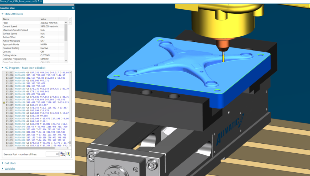
- CAM Software Processing: Computer-Aided Manufacturing (CAM) software takes your digital design and creates toolpaths - the exact movements your cutting tool will follow. This is where decisions about tool selection, cutting speeds, and approach angles get made.
- G-Code Generation: The CAM software uses a post-processor to convert toolpaths into G-code and M-code - the universal language CNC machines understand. G-code controls motion and coordinates, while M-code manages machine functions like spindle activation and coolant.
- Machine Setup: An operator loads the correct tools, secures the raw material in workholding fixtures, and uploads the G-code program to the machine's controller.
- Tool Path Execution: With the push of a button, the controller executes the program and machining begins. The spindle rotates the cutting tool while precision motors move along programmed axes.
- Finished Part: What started as raw stock emerges as a fully machined component, matching your original CAD specifications down to fractions of a millimeter.
The Machine Control Loop Explained
So how does cnc work at the machine level? The controller unit sits at the heart of every CNC machine, functioning like a sophisticated brain that interprets your programmed instructions and orchestrates all machine movements.
Here's what happens inside that control loop:
- Code Interpretation: The controller reads G-code line by line, translating coordinates and commands into electrical signals
- Motor Activation: Servo motors or stepper motors receive signals and move machine axes to precise positions
- Feedback Monitoring: Industrial machines use closed-loop servo systems with encoders that constantly verify position - if the actual position differs from the commanded position, the controller makes instant corrections
- Spindle Control: The controller manages spindle speed (RPM) based on M-code commands, adjusting for different tools and materials
According to ENCY CAD/CAM, this is precisely how cnc machine works: the controller reads the code, motors and drives move the machine axes, the spindle rotates the cutting tool or workpiece, and sensors keep motion on target throughout the operation.
Understanding cnc machining processes: a guide to machine tools and programming wouldn't be complete without mentioning that while CAM software is common, many modern controls also support conversational programming directly at the machine. This allows experienced operators to create simple programs without leaving the shop floor.
Now that you understand the digital-to-physical workflow, let's explore the specific operation types that actually remove material and shape your parts.
CNC Milling and Turning Operations Explained
You've seen how digital designs become machine instructions - but what actually happens when the cutting begins? The answer depends on which cnc machining operations you're using. Two fundamental approaches dominate precision manufacturing: milling and turning. Each excels at different tasks, and knowing when to use which can mean the difference between a perfect part and a costly mistake.
Material Removal Through Rotary Cutting
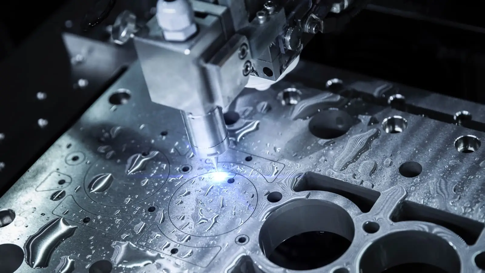
What is cnc milling, exactly? Picture a rotating cutting tool approaching a stationary workpiece from multiple angles, carving away material layer by layer. The cnc milling process uses rotary cutters spinning at high speeds to remove material systematically - creating everything from flat surfaces to intricate 3D contours.
Cnc machining milling operations fall into several categories, each designed for specific outcomes:
- Face Milling: The cutting action occurs at the end corners of the milling cutter, positioned perpendicular to the workpiece surface. This operation creates flat surfaces quickly and efficiently - perfect for squaring up raw stock or producing smooth, level faces on components. According to industry guides, face milling achieves surface roughness values between 1-3 μm for fine finishes.
- End Milling: The most versatile milling cnc machine operation. Cutting edges on both the sides and end of the tool allow axial and radial cutting simultaneously. Use end milling for slots, pockets, complex 3D shapes, and detailed profiles - it achieves roughness values around 1-2 μm.
- Peripheral Milling: Also called slab milling, this technique uses the cutter's outer edges to machine large flat surfaces. The tool axis runs parallel to the workpiece, making it ideal for removing significant material from broad areas.
Cnc milling machining handles an impressive range of materials - from soft aluminum alloys to hardened steels, plastics, composites, and even some ceramics. This versatility makes it the go-to choice when your part features intricate shapes, non-rotationally symmetric designs, or requires slots and pockets.
Achieving Cylindrical Precision Through Turning
Now imagine the opposite approach: instead of the tool spinning, the workpiece rotates while a stationary cutting tool removes material. That's cnc lathe machining in action.
CNC turning excels at producing cylindrical or rotationally symmetric parts - think shafts, pins, bushings, and any component with circular cross-sections. The workpiece spins in a chuck while precision-controlled cutting tools shape the exterior (and interior) surfaces with exceptional accuracy.
Common turning operations include:
- Facing: Creates flat surfaces on the workpiece ends
- Threading: Cuts precise internal or external threads
- Grooving: Produces grooves, recesses, or O-ring seats
- Boring: Enlarges or refines existing holes
- Knurling: Adds textured grip patterns to cylindrical surfaces
According to VMT CNC, turning achieves machining accuracy within a few microns, making it essential for industries demanding precision like aerospace, automotive, and medical device manufacturing. The process handles metals beautifully - aluminum alloys, stainless steel, brass, titanium, and various steels all turn with excellent results.
Matching Operations to Your Part Requirements
So when should you choose milling versus turning? It comes down to geometry, tolerances, and material characteristics. The following table provides a quick-reference guide for matching operation types to project requirements:
| Operation Type | Best Applications | Typical Tolerances | Material Suitability |
|---|---|---|---|
| Face Milling | Large flat surfaces, squaring stock, surface finishing | ±0.025 - 0.05 mm | All metals, plastics, composites |
| End Milling | Slots, pockets, complex 3D profiles, contours | ±0.01 - 0.025 mm | Aluminum, steel, brass, plastics, titanium |
| Peripheral Milling | Wide flat surfaces, heavy stock removal | ±0.05 - 0.1 mm | Softer metals, aluminum, mild steel |
| CNC Turning (Facing) | Flat end surfaces on cylindrical parts | ±0.01 - 0.025 mm | All turnable metals, engineering plastics |
| CNC Turning (External) | Shafts, pins, bushings, cylindrical components | ±0.005 - 0.02 mm | Aluminum, stainless steel, brass, titanium |
| CNC Turning (Threading) | Screws, bolts, threaded shafts, fittings | ±0.01 mm on pitch | Most metals, some engineering plastics |
Here's a practical rule of thumb: if your part is rotationally symmetric - meaning you could spin it on an axis and it looks the same - turning is typically faster and more economical. For parts with complex pockets, angled features, or asymmetric geometries, milling provides the flexibility you need.
Many precision components actually require both operations. A shaft with keyways, for example, might be turned for the cylindrical body and then milled for the slot features. Modern CNC turning centers with live tooling can even perform milling operations without removing the part - combining both capabilities in a single setup.
Of course, milling and turning represent just the foundation. When standard cutting operations can't achieve the surface finish or handle the material hardness your project demands, advanced techniques come into play.
Advanced CNC Operations Beyond Basic Cutting
What happens when milling and turning can't achieve the surface quality your project demands? Or when your material is so hard that conventional cutting tools simply won't survive the job? That's where advanced machining operations enter the picture. These specialized process machining techniques solve problems that basic cutting operations cannot - and understanding when to use them can save your project from costly failures.
Precision Surface Finishing Through Grinding
Sounds complex? CNC grinding is actually a straightforward concept: instead of cutting chips with a sharp-edged tool, grinding removes material through abrasion using a spinning wheel embedded with abrasive particles. The result? Surface finishes that conventional machining types simply cannot match.
Here's the reality: according to Norton Abrasives, precision CNC grinding achieves surface finishes ranging from 32 microinches Ra down to 4.0 microinches Ra and better. Compare that to traditional milling or turning, which typically produces finishes between 125 to 32 microinches Ra. When your mechanical machining specifications demand ultra-smooth surfaces, grinding becomes essential.
CNC grinding operations fall into several categories based on geometry:
- Surface/Creepfeed Grinding: Produces flat, precision surfaces - ideal for tool faces, fixture plates, and components requiring extreme flatness
- Outer Diameter (OD) Grinding: Achieves tight tolerances on cylindrical exteriors - think precision shafts and bearing journals
- Internal Diameter (ID) Grinding: Finishes bore surfaces where turning tools cannot reach required tolerances
- Centerless Grinding: Processes high volumes of cylindrical parts without requiring center mounting
When should you specify grinding in your cnc machine operations? Consider it mandatory when:
- Surface finish requirements fall below 16 microinches Ra
- Dimensional tolerances tighter than ±0.0005" are required
- Parts have been heat-treated and are too hard for conventional cutting
- Components require precise geometric relationships (roundness, cylindricity, parallelism)
The grinding process itself involves careful parameter control. Wheel speed, feed rate, depth of cut, and dressing conditions all influence the final surface quality. For critical applications, operators may increase spark-out passes - allowing the wheel to make additional light passes without infeed - to achieve mirror-like finishes.
Electrical Discharge Machining for Complex Geometries
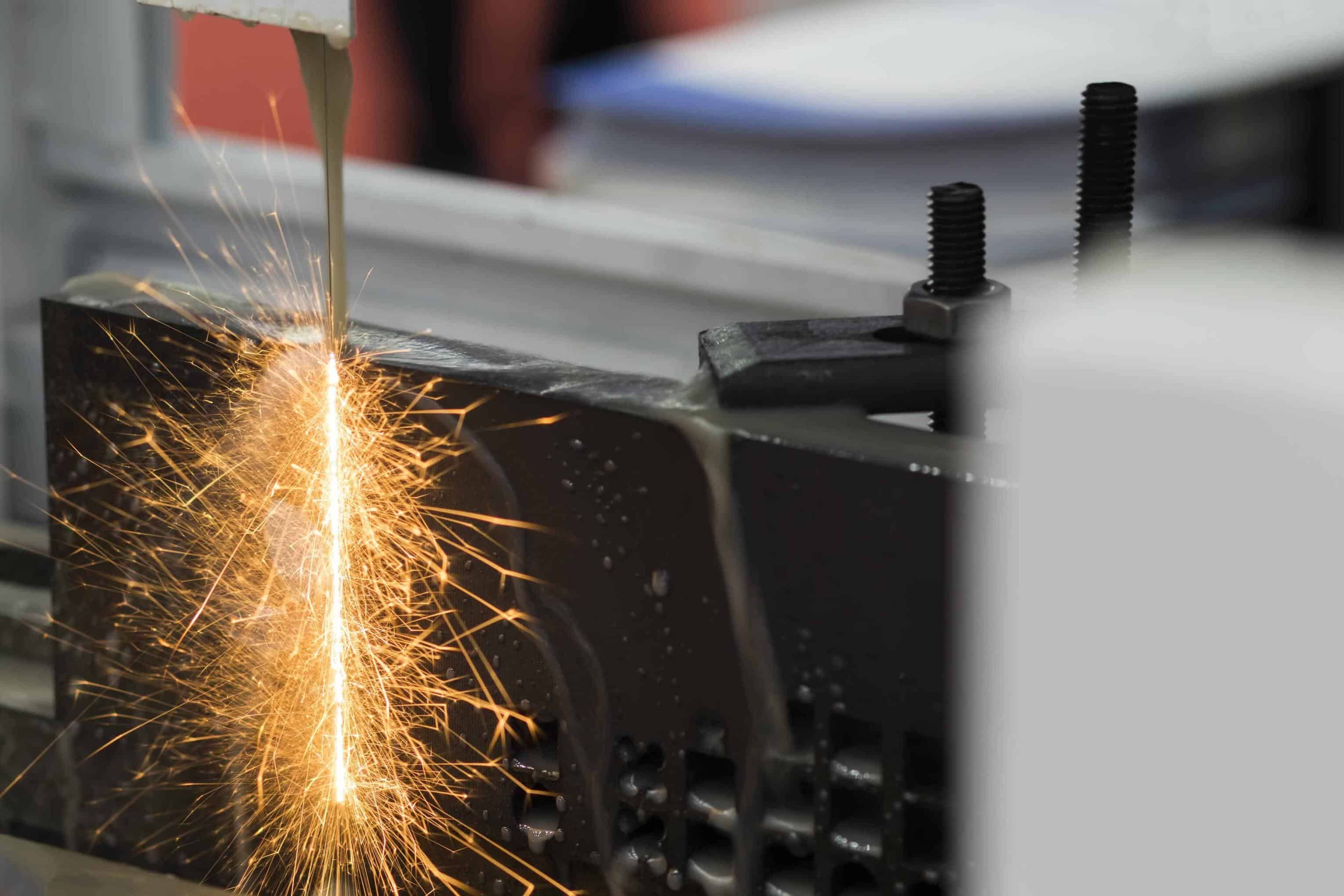
Imagine machining hardened steel without ever touching it. That's exactly what Electrical Discharge Machining (EDM) accomplishes. Instead of cutting, EDM removes material through rapid electrical sparks that vaporize tiny particles from the workpiece surface.
According to Xometry's technical resources, EDM achieves dimensional tolerances of ±0.0002" - precision that rivals grinding while handling materials that would destroy conventional cutting tools. The sparks generate temperatures between 14,500-21,500°F at the contact point, allowing EDM to machine virtually any conductive material regardless of hardness.
Three primary EDM variations address different machining challenges:
- Wire EDM: Uses a continuously fed thin wire electrode to cut through material like a cheese slicer - perfect for cutting complex 2D profiles through thick plates or creating precision die components
- Die Sinking EDM: A shaped electrode plunges into the workpiece, transferring its geometry to create cavities, molds, and intricate 3D features
- Hole Drilling EDM: Specialized for creating micro-holes, deep holes with extreme depth-to-diameter ratios, or holes in hardened materials where conventional drilling fails
Here are practical machining examples where EDM becomes the only viable solution:
- Cutting sharp internal corners that rotary tools cannot produce
- Machining hardened tool steels (60+ HRC) and tungsten carbide
- Creating undercuts and complex internal features impossible with straight tools
- Drilling micro-holes under 0.5mm diameter in aerospace components
- Removing broken taps or drill bits from expensive workpieces
- Producing injection mold cavities with textured surfaces
The trade-off? EDM operates significantly slower than conventional machining processes, making it economical only when no alternative exists. However, its non-contact nature means zero cutting forces - eliminating tool deflection concerns and enabling machining of thin-walled or delicate geometries.
Secondary Hole-Making Operations
Beyond grinding and EDM, several machining operations refine features created during primary machining:
- Drilling: Creates initial holes using rotating drill bits - the starting point for most hole-based features
- Boring: Enlarges existing holes with single-point tools to achieve precise diameters and improved roundness - essential when drilled holes aren't accurate enough
- Reaming: A finishing operation using multi-flute tools to achieve tight hole tolerances (typically ±0.0005") and superior surface finish after drilling
- Honing: Removes minimal material using abrasive stones to create crosshatch patterns - critical for cylinder bores and hydraulic components
These operations often work in sequence. A hole might be drilled to rough size, bored to near-final dimension, then reamed to achieve final tolerance and surface finish. Understanding this progression helps you specify the right machining operations for your tolerance requirements.
With this foundation in advanced operations, how do you actually decide which techniques to apply to your specific project?
Choosing the Right CNC Operation for Your Project
You've learned about milling, turning, grinding, and EDM - but when you're staring at a new part design, how do you actually decide which operation to use? What are cnc machines used for in your specific situation depends on a clear decision-making framework. Let's build one together.
Matching Part Geometry to Operation Type
Think about what you can do with a cnc machine as matching capabilities to requirements. The geometry of your part provides the first and most important clue for operation selection.
Ask yourself these questions about your part:
- Is it rotationally symmetric? Parts that look the same when spun around a central axis - shafts, pins, bushings, threaded fasteners - point directly toward CNC turning as your primary operation
- Does it have pockets, slots, or complex 3D surfaces? These features require milling operations, where a rotating tool approaches a stationary workpiece from multiple angles
- Are there sharp internal corners? Standard milling tools leave radiused corners. If true sharp corners are mandatory, you'll need EDM or alternative approaches
- How tight are your surface finish requirements? When specifications demand finishes below 16 microinches Ra, grinding or secondary finishing operations become necessary
The following table maps your project requirements directly to recommended cnc machine application choices:
| Decision Criteria | Low/Simple | Medium | High/Complex |
|---|---|---|---|
| Part Complexity | 3-axis milling or standard turning - handles prismatic shapes and basic cylindrical parts efficiently | 4-axis machining for parts requiring indexing or rotary features without continuous motion | 5-axis milling for contoured surfaces, undercuts, and multi-angle features in single setups |
| Material Hardness | Standard carbide tooling for aluminum, brass, mild steel (under 30 HRC) | Coated carbide or ceramic inserts for stainless steel, tool steels (30-50 HRC) | EDM or grinding for hardened materials above 50 HRC where conventional cutting fails |
| Tolerance Requirements | Standard machining (±0.005" / ±0.125mm) - achievable with basic setups | Precision machining (±0.001" / ±0.025mm) - requires climate control and quality tooling | Ultra-precision (±0.0005" / ±0.013mm or tighter) - demands grinding, honing, or specialized equipment |
| Surface Finish Needs | As-machined (Ra 3.2-6.3 μm) - standard milling or turning sufficient | Smooth machined (Ra 1.6-3.2 μm) - optimized cutting parameters and sharp tooling required | Polished/ground (Ra 0.4-1.6 μm or better) - secondary operations mandatory |
| Production Volume | Prototypes (1-10 units): prioritize flexibility over cycle time optimization | Low-volume production (10-500 units): balance setup costs against per-part efficiency | High-volume (500+ units): invest in optimized fixturing, multi-spindle machines, or automation |
Production Volume Considerations for Operation Selection
Different types of cnc machine configurations make economic sense at different production scales. Understanding cnc machine capabilities at each level helps you avoid overspending on prototypes or underinvesting in production tooling.
For prototypes and low volumes (1-50 parts):
- Prioritize 3-axis milling and standard turning - widely available and cost-effective
- Accept longer cycle times in exchange for simpler setups
- Use standard tooling rather than custom solutions
- Consider manual repositioning between operations if it avoids expensive 5-axis machine time
For medium volumes (50-500 parts):
- Invest in optimized workholding to reduce setup times
- Evaluate 4-axis or 5-axis machining if it eliminates multiple setups per part
- Custom tooling becomes justifiable when it significantly reduces cycle time
- Statistical process control (SPC) becomes valuable for maintaining consistency
For high volumes (500+ parts):
- Multi-spindle machines, pallet changers, and automation deliver significant per-part savings
- 5-axis machines often pay for themselves through reduced handling and improved accuracy
- Dedicated fixturing and tooling packages become essential investments
- Secondary operations like grinding may shift to dedicated equipment for throughput
When Multi-Axis Operations Justify Additional Cost
Among different types of cnc machines, 5-axis systems command premium pricing - ranging from $80,000 to over $500,000 compared to $25,000-$50,000 for 3-axis equipment. When does paying that premium make sense?
Consider 5-axis machining when your project involves:
- Complex contoured surfaces: Aerospace components, turbine blades, and impellers require continuous 5-axis motion for smooth surface transitions
- Multi-face machining: Parts requiring features on multiple sides benefit from single-setup processing, eliminating repositioning errors
- Undercuts and deep pockets: The additional rotational axes allow tool access impossible with fixed orientations
- Tight tolerances between angled features: When features on different faces must relate precisely, eliminating setup changes eliminates a major error source
According to Xometry's analysis, 5-axis machines offer increased efficiency and reduced tool changes through continuous milling operations. For complex parts, the higher machine cost often translates to lower total part cost through faster production and improved accuracy.
The key calculation: compare total part cost including setup time, machining time, and quality costs. A part requiring three 3-axis setups might actually cost more than single-setup 5-axis machining once you factor in handling time and potential tolerance stack-up from repositioning.
With your operation selected based on geometry, material, and volume, what happens when things don't go according to plan? The next section addresses the real-world problems operators encounter and how to solve them.
Troubleshooting Common CNC Machining Problems
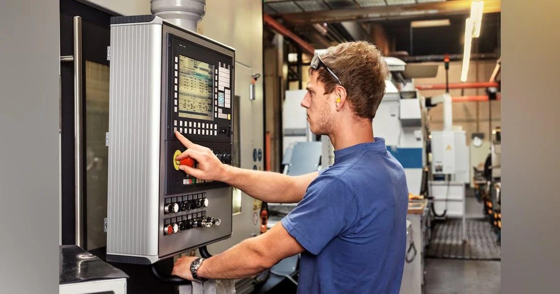
You've selected the right operation, loaded the program, and started the cut - but something isn't right. Maybe the surface looks rough, dimensions are drifting, or you're hearing that dreaded chatter. Learning how to operate a cnc machine means knowing what to do when problems arise. Let's walk through the most common issues and their practical solutions.
Diagnosing Tool Wear and Breakage Issues
When tools fail prematurely or break mid-operation, production stops and costs spike. Understanding why tools fail helps you prevent problems before they ruin your parts - or your schedule.
Symptom: Excessive tool wear or sudden breakage
- Cause: Incorrect cutting parameters - speeds and feeds either too aggressive or too conservative for the material
- Solution: According to industry troubleshooting guides, verify parameters against tooling manufacturer recommendations. Use spindle speed and feed overrides during test cuts to find stable combinations
- Cause: Poor chip evacuation causing recutting of chips
- Solution: Increase coolant pressure, adjust coolant nozzle aim to flush chips from the cutting zone, or modify toolpaths to improve chip clearance
- Cause: Excessive tool deflection from improper tool selection or too much stick-out
- Solution: Minimize tool extension - keep it as short as possible while still clearing the workpiece. Consider larger diameter tools or reduced depth of cut
- Cause: Wrong tool material or coating for the workpiece material
- Solution: Match tool substrate and coating to your application - TiAlN coatings excel in high-heat situations with steels, while uncoated carbide or diamond-coated tools work better for aluminum
Operating cnc machine tools effectively requires regular tool inspection. Implement a monitoring system that tracks tool usage and replaces cutters based on actual wear rather than arbitrary schedules. This condition-based approach prevents both premature changes and catastrophic failures.
Resolving Dimensional Accuracy Problems
Parts measuring out of tolerance? Dimensional drift during a production run? These problems have identifiable causes - and solutions.
Symptom: Parts consistently oversized or undersized
- Cause: Tool wear causing gradual dimensional shift
- Solution: Implement tool wear compensation in your program, or establish inspection intervals to catch drift before parts go out of spec
- Cause: Incorrect tool offset or geometry values
- Solution: Verify tool length and diameter offsets using a tool presetter or touch-off routine. Double-check values entered in the controller
Symptom: Dimensions drift during extended runs
- Cause: Thermal expansion of the machine, workpiece, or tooling as temperatures rise during machining cutting operations
- Solution: Allow the machine to warm up before critical cuts. For precision work, consider in-process probing to compensate for thermal growth. According to CNC troubleshooting experts, thermal effects represent one of the most overlooked sources of dimensional variation
- Cause: Loose workholding allowing part movement
- Solution: Verify clamping forces are adequate without distorting the part. Check fixture components for wear or damage
Symptom: Inconsistent dimensions between setups
- Cause: Machine not holding zero position reliably
- Solution: Check encoder connections and cables for looseness. Verify homing switches function correctly. Inspect ballscrews and linear guides for wear that could cause positioning errors
Eliminating Chatter and Poor Surface Finish
That high-pitched screech during machining? It's more than annoying - chatter destroys surface finish, accelerates tool wear, and can damage your machine. Here's how to work cnc machine operations without the noise.
Symptom: Visible chatter marks on machined surfaces
- Cause: Chip load too light - RPM too high or feedrate too low
- Solution: According to Haas CNC troubleshooting documentation, when chip load is too small, the tool resonates during the cut. Reduce spindle speed or increase feedrate to stabilize the cut
- Cause: Too many flutes engaged simultaneously
- Solution: Select a tool with fewer flutes, or reduce radial width-of-cut to engage fewer cutting edges at once
- Cause: Excessive tool stick-out causing deflection
- Solution: Use the shortest possible tool extension. Consider anti-vibration toolholders with tuned mass dampers or vibration-absorbing materials for deep-reach applications
- Cause: Inadequate workholding rigidity or machine foundation issues
- Solution: Verify the workpiece is clamped solidly. Check that the machine sits on a stable, continuous concrete foundation without cracks
Symptom: Poor surface finish without audible chatter
- Cause: Worn or damaged cutting tool
- Solution: Inspect cutting edges for wear patterns, chipping, or built-up edge. Replace tools showing visible wear
- Cause: Incorrect cutting parameters for the material
- Solution: Optimize speed and feed combinations for your specific material. Higher surface speeds often improve finish in many materials, while proper feed rates prevent rubbing
- Cause: Coolant not reaching the cutting zone
- Solution: Adjust coolant nozzle positioning to deliver fluid directly to the cut. Verify coolant concentration meets manufacturer recommendations for proper lubricity
Cnc machine working at peak performance requires systematic troubleshooting. When problems occur, resist the urge to change multiple variables at once. Adjust one parameter, observe the result, then proceed. This methodical approach identifies root causes rather than masking symptoms.
With troubleshooting skills in hand, you're ready to see how these operations integrate into real manufacturing environments across different industries.
CNC Operations Across Manufacturing Industries
How do the operations we've discussed translate into real-world production? Walk through any modern factory - whether it's building cars, aircraft, or medical devices - and you'll find CNC machines at the heart of the operation. Understanding how cnc in manufacturing works across different sectors reveals why these processes have become indispensable to global production.
Automotive Component Production at Scale
The automotive industry exemplifies high-volume manufacturing with cnc at its most demanding. When you're producing thousands of identical engine blocks, transmission housings, or brake components daily, consistency isn't optional - it's survival.
What makes automotive cnc machining industry requirements unique? Consider these factors:
- Engine blocks and cylinder heads: These castings require precision boring and milling operations to achieve bore tolerances within microns - essential for proper piston fit and compression
- Transmission components: Gears, shafts, and housings demand tight geometric tolerances to ensure smooth power transfer and durability over hundreds of thousands of miles
- Brake system parts: Calipers, rotors, and master cylinders must meet strict quality standards where dimensional accuracy directly impacts safety
- Suspension components: Control arms, steering knuckles, and wheel hubs require consistent machining to maintain handling characteristics across every vehicle produced
Manufacturing with cnc in automotive applications means balancing speed with precision. According to American Micro Industries, CNC machining enables engineers to accelerate research and development processes while manufacturing enhanced vehicles and parts faster. The machinery in production must deliver repeatable results across multi-shift operations, week after week.
The cost implications are significant. In high-volume automotive production, shaving seconds off cycle time translates to substantial annual savings. Operation selection directly impacts these economics - choosing between 3-axis and 5-axis machining, for example, involves calculating whether reduced setup time justifies higher machine rates.
Aerospace Precision Requirements
If automotive represents high-volume consistency, aerospace represents the opposite extreme - lower volumes with tolerances that push the boundaries of what's physically achievable.
The cnc machine industrial applications in aerospace involve materials and specifications that general manufacturing rarely encounters. According to Wevolver's aerospace CNC analysis, aerospace components operate under severe thermal, mechanical, and environmental loads, requiring significantly tighter tolerances than those used in general industrial machining. Critical features may call for tolerance bands measured in a few microns.
Machining manufacturing for aerospace typically includes:
- Structural components: Wing ribs, spars, and bulkheads machined from aluminum or titanium billets - often removing 90% or more of the original material to create lightweight, high-strength structures
- Engine hardware: Turbine blades, compressor discs, and combustor components machined from nickel superalloys like Inconel that retain strength at extreme temperatures
- Landing gear: High-strength steel and titanium components requiring precise bore alignments and load-bearing surfaces held to exceptionally tight geometric tolerances
- Avionics housings: Precision enclosures for flight computers, radar units, and sensors requiring tight dimensional control for board alignment and electromagnetic shielding
The cnc machine manufacture process for aerospace operates under AS9100D quality management standards - an extension of ISO 9001 developed specifically for aviation, space, and defense manufacturing. This means full inspection of critical features, complete material traceability from heat-lot identifiers through final assembly, and documentation retained for the life of the aircraft.
How Operation Selection Impacts Production Economics
Whether you're in automotive or aerospace - or medical devices, oil and gas, electronics, or marine applications - the operations you select directly affect your bottom line. Understanding these cost drivers helps you make smarter manufacturing decisions.
According to Xometry's cost analysis, the most important factors affecting CNC machined part costs include equipment, materials, design complexity, production volume, and finishing operations. Here's how these factors interact:
Equipment and operation complexity: Mills typically cost more than lathes due to more complex moving parts. Five-axis machines, while capable of producing complex geometries faster and more accurately, carry higher hourly rates than three-axis equipment. The key calculation: does reduced machining time offset higher machine costs?
Material machinability: Materials with low machinability take more time and consume more resources - cutting fluids, electricity, and tooling. Titanium's low thermal conductivity demands careful heat management and specialized tooling. Nickel superalloys cause rapid tool wear. These factors multiply cycle time and cost.
Volume economics: The cost per unit drops dramatically as quantity increases. Setup costs - CAD design, CAM preparation, and machine setup - are handled once for all parts. Xometry's data shows that cost per part for 1,000 units can be approximately 88% less than the cost of a single prototype.
Industry-specific applications with real component examples:
- Oil and gas: Valve bodies, pump components, drill bit parts, and pipeline fittings requiring corrosion-resistant materials and extreme durability for remote, harsh environments
- Medical devices: Surgical instruments, implant components, and diagnostic equipment housings machined from biocompatible materials to FDA-regulated specifications
- Electronics: Precision housings, heat sinks, and connector components requiring error-free micro-machining with parameters under 10 micrometers
- Marine: Propeller shafts, valve components, and hull fittings machined from corrosion-resistant materials for long-term water exposure
- Defense: Weapons components, communication equipment housings, and vehicle parts meeting strict government regulations and security requirements
The cnc machining industry continues evolving as these sectors push for lighter materials, tighter tolerances, and faster production cycles. From prototype through mass production, CNC operations provide the flexibility to serve single-piece orders and million-unit runs alike - making them foundational to modern manufacturing ecosystems.
With this understanding of industry applications, how do you find a manufacturing partner capable of meeting your specific production requirements?
Selecting a CNC Machining Partner for Production Success
You understand the operations, you've selected the right processes for your project - but who actually machines your parts? Finding the right production cnc machining partner can mean the difference between a smooth product launch and costly delays. Whether you need a single prototype or thousands of production parts, knowing what is a cnc provider's true capabilities requires looking beyond their website claims.
Evaluating CNC Service Provider Capabilities
What is cnc machinery capability really about? It comes down to matching a provider's equipment, expertise, and systems to your specific requirements. According to industry evaluation guides, systematic assessment across multiple dimensions ensures you partner with someone who can actually deliver.
Here's what to examine when evaluating cnc machining and manufacturing partners:
- Equipment capabilities and condition: Request machine lists showing make, model, and axis configurations. Modern CNC equipment from reputable manufacturers (Mazak, DMG Mori, Haas) typically indicates investment in precision. Ask about calibration schedules - well-maintained machines undergo regular verification against traceable standards
- Tolerance and precision track record: Can they actually achieve your required tolerances? Request sample parts with measurement reports or capability studies (Cpk values) demonstrating process stability. A provider claiming ±0.001" capability should have data proving it
- Material expertise: The machining parameters for aluminum differ dramatically from titanium or Inconel. Ask for case studies or project examples involving materials similar to yours - this demonstrates genuine experience rather than theoretical knowledge
- Workforce qualifications: Skilled operators matter as much as good machines. Inquire about training programs, certifications, and operator-to-machine ratios. According to evaluation best practices, a ratio of 1:2 or better ensures adequate oversight during production
- Scalability from prototype to production: Can they handle your initial 10-piece prototype run and then scale to 10,000 units? Look for providers with diverse equipment - both flexible machining centers for low volumes and production-oriented machines with automation for high volumes
- Lead time flexibility: Production schedules rarely go as planned. Ask about rush capabilities and typical lead times. Some providers offer rapid prototyping with turnaround as fast as one working day for urgent projects
Quality Certifications That Matter for Precision Parts
Certifications aren't just wall decorations - they represent documented proof that a provider's cnc manufacturing process meets externally verified standards. Understanding which certifications matter for your industry helps you filter candidates quickly.
According to American Micro Industries' certification guide, the following credentials signal genuine commitment to quality:
- IATF 16949 (Automotive): The global standard for automotive quality management, combining ISO 9001 principles with sector-specific requirements for continuous improvement, defect prevention, and rigorous supplier oversight. If you're sourcing automotive components, this certification is often mandatory - and indicates the provider understands the relentless quality demands of automotive production
- ISO 9001: The internationally recognized baseline for quality management systems. It demonstrates documented workflows, performance monitoring, and corrective action processes. While foundational, ISO 9001 alone may not suffice for regulated industries
- AS9100 (Aerospace): Extends ISO 9001 with aerospace-specific requirements for risk management, product traceability, and documentation control throughout complex supply chains. Essential for any aerospace-related machining
- ISO 13485 (Medical): The definitive quality standard for medical device manufacturing, requiring strict controls over design, traceability, and risk mitigation. Mandatory for implants, surgical instruments, and diagnostic equipment components
- NADCAP (Special Processes): Accreditation for aerospace and defense special processes including heat treating, chemical processing, and nondestructive testing. Provides additional validation beyond general quality certifications
Beyond certifications, evaluate the provider's quality control practices. Statistical Process Control (SPC) implementation demonstrates data-driven manufacturing - tracking key dimensions throughout production runs to catch drift before parts go out of spec. Ask about inspection equipment: CMMs (coordinate measuring machines), optical comparators, surface roughness testers, and other metrology tools indicate serious quality infrastructure.
Putting It All Together: A Practical Evaluation Framework
The cnc machine manufacturing process evaluation doesn't have to be overwhelming. Use this structured approach:
| Evaluation Criteria | What to Request | Red Flags |
|---|---|---|
| Equipment Capabilities | Machine list with specifications, calibration records | Outdated equipment, no calibration documentation |
| Quality Certifications | Current certificates, audit results | Expired certifications, reluctance to share |
| Precision Track Record | Sample parts with inspection reports, Cpk studies | No measurement data, vague tolerance claims |
| Material Experience | Case studies with your specific materials | No relevant project examples |
| Scalability | Examples of prototype-to-production transitions | Only handles one end of the volume spectrum |
| Lead Time Performance | Historical on-time delivery rates | No tracking data, missed delivery history |
For automotive applications specifically, providers with IATF 16949 certification and demonstrated SPC implementation offer the quality assurance that OEMs and Tier 1 suppliers demand. Shaoyi Metal Technology exemplifies this approach - their IATF 16949 certification, strict SPC quality control, and ability to scale from rapid prototyping (with lead times as fast as one working day) to mass production makes them a capable partner for automotive CNC machining solutions requiring consistent precision across high volumes.
The machining partner you select becomes an extension of your manufacturing capability. Invest time upfront in thorough evaluation - it pays dividends in quality, reliability, and peace of mind throughout your production program.
Frequently Asked Questions About CNC Machining Operations
1. Is CNC operation a good career?
CNC machining offers excellent career prospects due to high demand across automotive, aerospace, and medical industries. Skilled CNC machinists command competitive salaries because shops need qualified operators to run precision equipment. The career provides job security, opportunities for advancement into programming and supervision roles, and the satisfaction of creating tangible precision components used in everything from vehicles to surgical instruments.
2. What are the 7 major parts of a CNC machine?
The seven key CNC machine components include: the Machine Control Unit (MCU) that interprets programmed instructions, input devices for loading programs, the drive system with motors for axis movement, cutting tools for material removal, feedback systems with encoders for position verification, the bed and table for workpiece support, and the cooling system for thermal management during machining operations.
3. What is the difference between CNC milling and CNC turning?
CNC milling uses rotating cutting tools to remove material from a stationary workpiece, ideal for complex 3D shapes, pockets, and slots. CNC turning rotates the workpiece while stationary tools cut material, best for cylindrical parts like shafts and bushings. Choose turning for rotationally symmetric parts and milling for prismatic geometries requiring multi-angle machining.
4. How do I choose the right CNC operation for my project?
Select CNC operations based on part geometry, material hardness, tolerance requirements, and production volume. Rotationally symmetric parts suit turning, while complex shapes need milling. Hardened materials above 50 HRC may require EDM or grinding. For prototypes, prioritize flexibility; for high volumes, invest in automation and optimized fixturing to reduce per-part costs.
5. What certifications should a CNC machining partner have?
Key certifications depend on your industry: IATF 16949 for automotive components ensures rigorous quality management and supplier oversight; AS9100 covers aerospace requirements; ISO 13485 applies to medical devices. ISO 9001 provides a quality baseline. Also verify SPC implementation, calibration records, and inspection equipment capabilities to ensure the provider can meet your precision requirements.