 Small batches, high standards. Our rapid prototyping service makes validation faster and easier —

Carbide Inserts For Stamping Dies: Grade Selection That Stops Premature Failure
Understanding Carbide Inserts in Stamping Die Applications
When your stamping operation starts producing inconsistent parts or you notice accelerated wear on cutting edges, the culprit often lies in one critical component: the carbide insert. But what exactly are these components, and why do they matter so much to your die's performance?
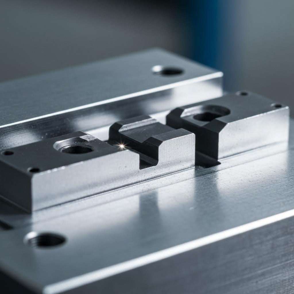
Carbide inserts for stamping dies are precision-engineered wear components made primarily from tungsten carbide, designed to be mounted within the die body at high-stress contact points where they absorb the brunt of repetitive cutting, forming, and blanking operations.
What Are Carbide Inserts in Stamping Applications
Think of a stamping die as having two distinct parts: the structural body and the working surfaces. The die body provides rigidity and houses all the moving components, while carbide inserts serve as the actual cutting edges and wear surfaces that contact the workpiece material. This separation is intentional and highly strategic.
Tungsten carbide inserts consist of hard tungsten carbide particles bonded together by a metallic binder, typically cobalt. This combination creates a material that offers exceptional hardness while maintaining enough toughness to withstand the repetitive impact forces inherent in stamping operations. A single tungsten carbide insert can outlast conventional tool steel components by factors of ten to twenty times, depending on the application.
You'll find carbide tips positioned at punch noses, die cutting edges, form stations, and anywhere else the tooling directly engages the sheet metal. These locations experience the highest stress concentrations and wear rates during production runs.
The Role of Replaceable Wear Components in Die Design
Why not simply manufacture the entire die from carbide? The answer comes down to practicality and economics. Carbide is significantly more expensive than tool steel and considerably more difficult to machine into complex shapes. By using replaceable carbide inserts only at critical wear points, manufacturers achieve the best of both worlds: economical die construction with premium wear resistance where it matters most.
When a carbide insert eventually wears beyond acceptable tolerances, you simply remove it and install a fresh component. This modular approach minimizes downtime compared to reconditioning or replacing an entire die section. The cobalt binder content in your inserts directly influences this wear behavior, affecting both how long the insert lasts and how it ultimately fails.
Throughout this guide, you'll explore the material science behind carbide composition, learn how to match grades to specific workpiece materials, and discover practical strategies for preventing premature failure. Understanding these fundamentals transforms carbide insert selection from guesswork into a systematic engineering decision.

Material Science Behind Carbide Composition and Performance
Ever wondered why two carbide inserts that look identical can perform dramatically differently in the same stamping application? The answer lies in their internal composition, specifically the delicate balance between tungsten carbide particles and the cobalt binder that holds everything together. Understanding this relationship gives you the power to select grades that match your exact operational demands.
Tungsten Carbide and Cobalt Binder Ratios Explained
Imagine tungsten carbide particles as extremely hard stones embedded in a softer metallic cement. The stones provide wear resistance and hardness, while the cement, in this case cobalt, provides the toughness needed to absorb impact without shattering. Adjusting the ratio between these two components fundamentally changes how the insert behaves under stress.
Cobalt content in stamping die inserts typically ranges from 6% to 15% by weight. Lower cobalt percentages, around 6% to 8%, produce inserts with maximum hardness and wear resistance. These grades excel in applications where abrasion is the primary concern, such as stamping abrasive materials or running extremely high volumes. However, they sacrifice some impact resistance in the process.
As you increase cobalt content toward 10% to 15%, the inserts become progressively tougher. They can absorb more shock loading without chipping or cracking, making them ideal for heavy blanking operations or when stamping thicker materials. The trade-off is slightly reduced wear resistance and hardness. When working with a reliable carbide supply partner, you'll notice they offer multiple grades specifically because no single formulation works optimally across all applications.
Think of selecting cobalt content like choosing between a sports car and an off-road vehicle. Both get you where you need to go, but each excels in different conditions. A facing insert used in light finishing operations might prioritize hardness, while a punch tip absorbing repeated heavy impacts needs that extra toughness from higher cobalt content.
How Grain Size Affects Stamping Performance
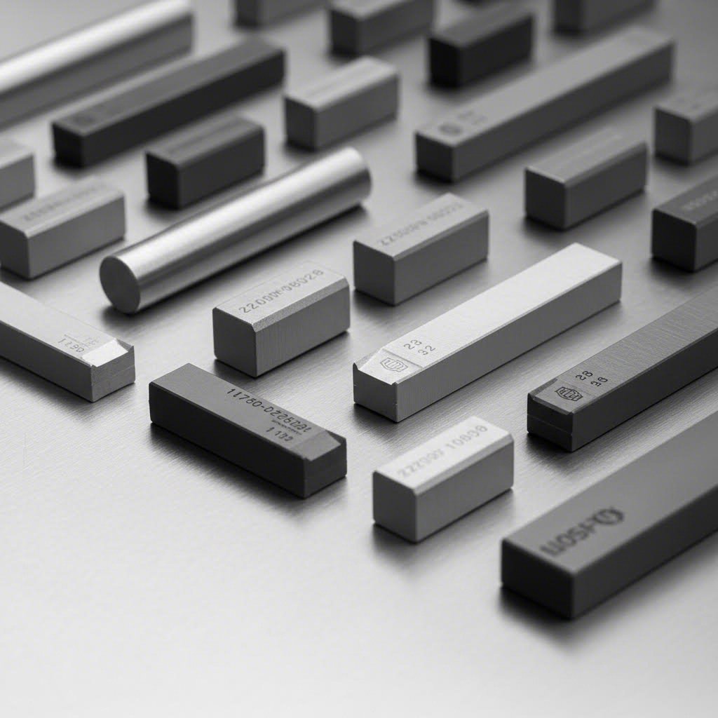
Beyond binder content, the size of the tungsten carbide particles dramatically influences insert performance. Grain sizes are typically classified into four categories:
- Nano-grain (below 0.5 microns): Provides exceptional edge sharpness and wear resistance for precision stamping
- Submicron (0.5 to 1.0 microns): Offers an excellent balance of hardness and toughness for general-purpose applications
- Fine-grain (1.0 to 2.0 microns): Delivers good toughness with moderate wear resistance
- Coarse-grain (above 2.0 microns): Maximizes toughness for severe impact applications
Smaller grain sizes pack more tightly together, creating fewer voids and producing higher hardness values. Rectangular carbide blanks machined from nano-grain materials hold sharper cutting edges longer, which proves critical when stamping thin materials or maintaining tight dimensional tolerances. However, finer grains also mean less forgiving behavior under shock loading.
Coarse-grain carbides sacrifice some hardness but gain significant resistance to chipping and fracture. When your operation involves heavy blanking or experiences occasional misfeeds that shock the tooling, coarser grain structures provide a safety margin against catastrophic failure.
| Cobalt Content | Hardness (HRA) | Transverse Rupture Strength | Recommended Applications |
|---|---|---|---|
| 6% | 92.5 - 93.5 | 1,500 - 1,800 MPa | High-volume stamping of thin materials, precision blanking |
| 8% | 91.5 - 92.5 | 1,800 - 2,200 MPa | General-purpose stamping, progressive die stations |
| 10% | 90.5 - 91.5 | 2,200 - 2,600 MPa | Medium blanking, forming operations with moderate impact |
| 12% | 89.0 - 90.5 | 2,600 - 3,000 MPa | Heavy blanking, thicker materials, higher shock loads |
| 15% | 87.0 - 89.0 | 3,000 - 3,500 MPa | Severe impact applications, interrupted cuts, rough conditions |
Notice how hardness decreases as cobalt content rises, while transverse rupture strength, which measures resistance to breaking under bending loads, increases substantially. This inverse relationship is why inserts carbide manufacturers offer such a wide range of grades. Selecting the right combination of binder content and grain size for your specific workpiece material and stamping conditions prevents the premature failures that plague poorly matched tooling.
Selecting Carbide Grades for Different Workpiece Materials
Now that you understand how cobalt content and grain size shape insert behavior, the next question becomes practical: which grade works best for the specific material you're stamping? The answer depends heavily on the workpiece properties because different metals create vastly different demands on your tooling.
Stamping mild steel produces moderate abrasive wear. Stamping stainless steel generates intense heat and galling. Stamping aluminum creates adhesion problems. Each scenario calls for a distinct carbide formulation, and choosing incorrectly leads to either premature wear or unexpected chipping. Let's break down the selection criteria for the most common workpiece materials.
Carbide Selection for Steel and Stainless Steel Stamping
When you're stamping carbon steel or low-alloy steel, abrasive wear dominates the failure mode. The iron oxides and scale present on steel surfaces act like sandpaper against your cutting edges, gradually grinding them down with each stroke. For these applications, prioritize harder carbide grades with lower cobalt content, typically in the 6% to 10% range.
Submicron to fine-grain structures work exceptionally well here. They maintain sharp cutting edges longer, producing cleaner sheared surfaces and tighter dimensional control. If your operation involves high-volume production runs on thin-gauge steel, a 6% cobalt nano-grain carbide cutting insert delivers maximum tool life before requiring replacement or regrinding.
Stainless steel presents a completely different challenge. Its work-hardening tendency means the material becomes progressively harder as you deform it. This creates higher cutting forces and more localized stress on your insert edges. Additionally, stainless steel's chromium content promotes adhesion to carbide surfaces, causing galling and material buildup that accelerates wear.
For stainless steel stamping, consider these adjustments:
- Increase cobalt content to 10% to 12% for added toughness against higher cutting forces
- Select fine-grain structures that balance edge retention with chip resistance
- Ensure adequate lubrication to minimize adhesion and heat buildup
- Consider coated inserts that reduce friction at the tool-workpiece interface
High-strength alloys, including advanced high-strength steels used in automotive applications, demand the toughest grades in your arsenal. The extreme forces required to shear these materials can crack or chip harder carbide formulations. Moving toward 12% to 15% cobalt content provides the impact resistance needed to survive these demanding conditions, even though you'll sacrifice some wear resistance.
Optimizing Insert Choice for Aluminum and Copper Applications
Softer metals like aluminum and copper seem like they should be easy on your tooling, but they introduce their own unique problems. Aluminum's primary issue is adhesion. The soft metal wants to stick to carbide surfaces, building up on cutting edges and eventually pulling particles from the insert itself. This adhesive wear mechanism differs fundamentally from the abrasive wear you see with steel.
For aluminum stamping, sharp edges are critical. Nano-grain and submicron carbide grades with lower cobalt content produce the keen edges needed to shear cleanly through aluminum without allowing material buildup. Many shops also find success with polished insert surfaces that reduce friction and make it harder for aluminum to adhere.
Copper and brass behave similarly to aluminum regarding adhesion but add another consideration: these materials work-harden at moderate rates and can create unexpectedly high cutting forces when stamping thick gauges. A cutting insert with 8% to 10% cobalt content typically handles copper alloys well, providing enough toughness for the forming forces while maintaining the edge sharpness needed to prevent material sticking.
Interestingly, the principles governing carbide selection in stamping parallel those used for inserts for turning and other machining operations. Just as carbide inserts for lathe applications must match the workpiece material being cut, stamping inserts require the same thoughtful material pairing. The physics of metal deformation remain consistent across manufacturing processes.
How Material Thickness and Stamping Speed Influence Selection
Beyond workpiece composition, two operational parameters significantly impact your grade selection: material thickness and stamping speed.
Thicker materials require greater force to shear or form, translating directly into higher stress concentrations at your insert edges. When stamping heavy-gauge stock, shift toward tougher grades with higher cobalt content. The increased transverse rupture strength prevents edge chipping under these intensified loads. Conversely, thin materials generate less impact per stroke, allowing you to prioritize wear resistance with harder, lower-cobalt formulations.
Stamping speed affects heat generation and impact frequency. High-speed progressive die operations cycle hundreds of times per minute, generating significant heat at cutting edges. This thermal stress can cause micro-cracking in carbide that's too hard and brittle. Faster operations generally benefit from slightly tougher grades that tolerate thermal cycling better.
| Workpiece Material | Recommended Cobalt % | Preferred Grain Size | Primary Wear Mode | Key Selection Considerations |
|---|---|---|---|---|
| Mild Carbon Steel | 6% - 8% | Submicron to Fine | Abrasive | Maximize hardness for long wear life |
| Stainless Steel | 10% - 12% | Fine | Adhesive + Abrasive | Balance toughness with galling resistance |
| Aluminum Alloys | 6% - 8% | Nano to Submicron | Adhesive | Sharp edges, polished surfaces, proper lubrication |
| Copper and Brass | 8% - 10% | Submicron to Fine | Adhesive | Edge sharpness with moderate toughness |
| High-Strength Alloys | 12% - 15% | Fine to Coarse | Impact + Abrasive | Prioritize toughness over hardness |
Balancing Wear Resistance Against Chipping Resistance
Every carbide grade selection involves a fundamental trade-off. Harder grades with lower cobalt content resist gradual wear magnificently but prove vulnerable to sudden impact loads or edge chipping. Tougher grades with higher cobalt survive shock loading but wear faster under normal operation.
Ask yourself these questions when evaluating options for carbide cutting inserts:
- Does your application involve consistent, predictable loading, or do you experience occasional misfeeds and double-hits?
- Is your press properly maintained with tight gibbing, or does it exhibit some play that creates off-center loading?
- Are you stamping uniform material, or does thickness vary within your incoming stock?
- How critical is burr-free edge quality versus maximizing time between regrinds?
Shops with well-maintained equipment, consistent material supply, and tight process control can push toward harder grades and extract maximum tool life. Operations dealing with variable conditions or older presses benefit from the insurance that tougher grades provide against unexpected loading events.
Understanding these material-specific requirements and operational trade-offs positions you to make informed grade selections. However, even the perfect carbide grade won't perform optimally if it's fighting against the wrong die design. Different die configurations create unique stress patterns and wear conditions that further refine your insert choices.
Carbide Inserts Compared to Tool Steel and Alternative Materials
So you've identified the right carbide grade for your workpiece material, but here's a question that often gets overlooked: should you even be using carbide in the first place? While carbide tool inserts dominate high-performance stamping applications, they're not always the most economical choice. Understanding when carbide makes sense versus when alternative materials deliver better value helps you allocate your tooling budget strategically.
Let's examine how carbide stacks up against the most common alternatives: D2 tool steel, M2 high-speed steel (HSS), and advanced ceramics. Each material occupies a specific niche in stamping die applications, and the best choice depends on your production volumes, workpiece material, and tolerance requirements.
Carbide vs Tool Steel in High-Volume Stamping
Tool steels like D2 have served stamping operations for decades. They're relatively easy to machine, can be heat-treated to achieve respectable hardness, and cost significantly less than carbide. For prototype runs or low-volume production, D2 tool steel often makes perfect economic sense.
However, when production volumes climb into the hundreds of thousands or millions of parts, the calculus shifts dramatically. A D2 insert might require regrinding every 50,000 to 100,000 strokes, while a properly selected carbide cutter handling the same operation can run 500,000 to over 1,000,000 strokes before needing attention. Each regrind means production downtime, labor costs, and potential dimensional drift as the tool geometry changes.
Consider this scenario: you're running a progressive die at 400 strokes per minute, producing automotive brackets. With D2 inserts, you might stop for regrinding every shift or two. Switch to carbide, and that same station runs for weeks without intervention. The insert tooling cost per part drops substantially despite carbide's higher initial price.
The break-even point typically occurs somewhere between 100,000 and 250,000 parts, depending on the specific application. Beyond this volume, carbide's extended service life more than compensates for its premium price. Below this threshold, tool steel's lower upfront cost and easier machinability often win out.
When Ceramic or HSS Alternatives Make Sense
M2 high-speed steel occupies a middle ground between conventional tool steel and carbide. It offers better hot hardness than D2, meaning it retains its cutting edge even when heat builds up during high-speed operations. For applications where heat generation is a concern but carbide's cost seems excessive, M2 provides a viable compromise.
HSS works particularly well in forming operations where the tool insert experiences less abrasive wear but still needs to resist deformation under load. Draw dies and bending stations that don't involve actual cutting often perform adequately with M2 components at a fraction of carbide's cost.
Ceramic materials represent the opposite end of the spectrum from tool steel. They're extremely hard and wear-resistant, exceeding even the hardest carbide grades. However, ceramics are also exceptionally brittle. In stamping applications involving any impact loading, shock, or vibration, ceramic inserts tend to crack or shatter catastrophically.
Where do ceramics excel? In highly specialized operations stamping abrasive materials under very controlled conditions with minimal impact. Some electronics stamping applications involving ceramic substrates or heavily filled plastics benefit from ceramic tooling. For mainstream metal stamping, though, ceramics remain too fragile for practical use.
Interestingly, the milling insert l rectangular geometries used in some die applications sometimes incorporate ceramic materials when the application involves light finishing cuts on hardened surfaces. However, these represent niche cases rather than typical stamping scenarios.
| Material | Hardness (HRC/HRA) | Toughness | Wear Resistance | Relative Cost | Typical Tool Life (strokes) |
|---|---|---|---|---|---|
| D2 Tool Steel | 58-62 HRC | Good | Moderate | 1x (baseline) | 50,000 - 150,000 |
| M2 HSS | 62-65 HRC | Good | Moderate-High | 1.5x - 2x | 75,000 - 200,000 |
| Carbide (10% Co) | 90-91 HRA | Moderate | Excellent | 5x - 10x | 500,000 - 2,000,000 |
| Ceramic | 93-95 HRA | Poor | Outstanding | 8x - 15x | Variable (fragile) |
Making the Economic Decision
When evaluating carbide cutters against alternatives, calculate the total cost per part rather than focusing solely on initial tool insert price. Factor in:
- Downtime costs: What does each production stoppage cost in lost output?
- Regrind expenses: Labor, equipment time, and logistics for tool reconditioning
- Quality consistency: Does tool wear create dimensional drift requiring more frequent adjustments?
- Scrap rates: Do worn tools produce more rejected parts before replacement?
High-volume automotive and appliance stamping operations almost universally favor carbide despite its premium pricing. The math simply works out better when you're producing millions of identical parts. Conversely, job shops handling varied short runs often maintain a mix of tool steel and carbide tooling, deploying each where it makes the most economic sense.
One often-overlooked factor is regrindability. Tool steel inserts can be reground many times before the geometry becomes unusable. Carbide allows fewer regrinds due to its hardness but requires specialized diamond grinding equipment. If your shop lacks carbide regrinding capability, factor in outside service costs or the expense of replacement versus reconditioning.
Ultimately, the right material choice depends on your specific production context. Carbide dominates when volumes are high, precision matters, and downtime costs money. Tool steel remains viable for lower volumes and applications where its limitations don't impact quality. Ceramics wait in the wings for specialized situations where their extreme hardness justifies their fragility.
With material selection clarified, the next consideration involves how different die configurations affect your insert requirements. Progressive dies, transfer dies, and compound dies each create unique stress patterns that influence both carbide grade selection and insert positioning strategies.
Application Guidance for Progressive Transfer and Compound Dies
You've selected the right carbide grade for your workpiece material and confirmed that carbide makes economic sense for your production volumes. Now comes a question that trips up even experienced die designers: how does your die configuration affect insert placement, geometry, and grade selection? Progressive dies, transfer dies, and compound dies each create distinct stress patterns that demand tailored approaches to carbide integration.
Think of it this way: the same carbide grade that excels in a single-hit blanking operation might fail prematurely in a progressive die's forming station. Understanding these application-specific demands helps you position your metal punches and dies for maximum longevity and consistent part quality.
Carbide Insert Considerations for Progressive Dies
Progressive dies move strip material through multiple stations, performing different operations at each stop. This configuration creates a fascinating wear pattern challenge because each station experiences fundamentally different stresses.
Early stations typically handle piercing and blanking operations, subjecting stamping die punches to high shear forces and abrasive wear. Middle stations often perform forming, bending, or coining operations where the tooling experiences more gradual pressure than sudden impact. Final stations might involve cutoff or trimming operations that combine shearing with potential edge loading from accumulated strip positioning errors.
What does this mean for your carbide insert strategy? You'll likely need different grades at different stations rather than a one-size-fits-all approach. Consider these station-specific guidelines:
- Piercing stations: Harder grades with 6% to 8% cobalt content excel here. The repetitive punching action creates consistent abrasive wear, and sharper edges produce cleaner holes with less burr.
- Forming stations: Moderate grades with 10% to 12% cobalt handle the sustained pressure and potential side loading better. These stations rarely see the sharp impact of piercing but must resist deformation under load.
- Cutoff stations: Tougher grades around 10% cobalt provide insurance against the accumulated strip positioning variations that create off-center loading at the final separation point.
Strip progression also creates a unique consideration: stations near the strip entry point see cleaner, more consistent material, while downstream stations encounter work-hardened material that's been punched, bent, and formed multiple times. This progressive hardening effect increases cutting forces at later stations, sometimes justifying tougher carbide grades even for operations that would normally favor harder inserts.
Mounting methods matter significantly in progressive die applications. Carbide punches must be secured rigidly enough to prevent any movement during operation yet remain replaceable for maintenance. Press-fit mounting works well for smaller punches, while larger inserts often use mechanical retention with screws or clamps. The mounting approach affects how stress transfers through the insert, influencing both wear patterns and failure modes.
Transfer Die and Compound Die Insert Requirements
Transfer dies move individual blanks between stations rather than progressing a continuous strip. This fundamental difference changes the stress dynamics your carbide inserts face.
Without the strip's inherent guidance, each blank must be precisely located at every station. Any positioning error translates directly into off-center loading on your carbide punches. This reality pushes transfer die applications toward tougher carbide grades that tolerate occasional misalignment without chipping. Even if your transfer mechanism operates with excellent precision, building in some toughness margin protects against the inevitable positioning deviations that occur over millions of cycles.
Transfer dies also typically handle larger, heavier blanks than progressive operations. The increased mass means greater momentum during each stroke, translating to higher impact forces at the moment of contact. Your metal punches and die components must absorb this energy without damage, favoring grades in the 10% to 12% cobalt range for most stations.
Compound dies present yet another distinct challenge. These dies perform multiple operations simultaneously in a single stroke, typically combining blanking with piercing, or cutting with forming. The simultaneous nature of these operations creates complex stress states that single-operation dies never experience.
Key considerations for compound die carbide inserts include:
- Simultaneous loading: Multiple cutting edges engage the workpiece at once, requiring balanced forces to prevent lateral movement. Inserts must be positioned symmetrically to distribute loads evenly.
- Stress interaction: When piercing occurs simultaneously with blanking, the material flow from one operation affects the stress state at adjacent operations. Tougher grades help absorb these interacting forces.
- Knockout requirements: Compound dies must eject parts and slugs in close quarters. Carbide surfaces involved in knockout or stripping functions need good surface finish to prevent sticking.
- Heat concentration: Multiple simultaneous operations generate more heat in a smaller area than distributed operations. Consider grades with slightly higher cobalt content to tolerate thermal cycling.
Typical failure points in compound dies concentrate where operations interface. The junction between a blanking edge and an adjacent forming surface, for example, experiences complex stress states that neither operation would create in isolation. Positioning carbide inserts to span these interfaces with unified sections, rather than placing separate inserts that meet at the high-stress junction, significantly improves reliability.
How Press Parameters Influence Insert Selection and Positioning
Your carbide selection doesn't exist in isolation from the press that drives it. Tonnage, speed, and stroke length all influence how your inserts perform and wear.
Press tonnage directly affects the force transmitted through your tooling. Higher-tonnage applications, particularly those approaching the press's rated capacity, demand tougher carbide grades. Running a 200-ton press at 180 tons leaves little margin for force spikes from material variations or slight misalignments. In these scenarios, carbide punches with 12% to 15% cobalt content provide essential fracture resistance.
Stamping speed affects both heat generation and impact frequency. High-speed presses cycling at 400 or more strokes per minute subject inserts to rapid thermal cycling that can cause micro-cracking in brittle grades. Faster operations typically benefit from grades with slightly higher cobalt content than you'd choose for the same operation running slower. The added toughness compensates for thermal stress accumulation.
Stroke length influences the velocity at which punches contact the workpiece. Longer strokes allow punches to accelerate more before impact, increasing instantaneous forces at the moment of engagement. Snap-through presses and high-velocity stamping operations require careful attention to carbide grade selection, with tougher formulations providing insurance against the elevated impact energies.
Consider these press-related factors when positioning your carbide inserts:
- Tonnage distribution: Position the most critical carbide components in areas where press force concentrates uniformly rather than where the platen might flex or deflect.
- Alignment sensitivity: Older presses with worn guides or excessive play require tougher inserts throughout to compensate for off-center loading.
- Lubrication delivery: Position inserts where lubrication reaches effectively. Starved cutting edges wear dramatically faster and run hotter.
- Accessibility: Install frequently replaced inserts in positions that allow relatively quick changeout without extensive die disassembly.
Matching your carbide insert strategy to both die type and press characteristics creates a comprehensive approach to premature failure prevention. However, even the best-planned installation will eventually show wear. Recognizing the difference between normal wear progression and abnormal failure indicators allows you to intervene before quality suffers or catastrophic damage occurs.
Failure Modes Troubleshooting and Maintenance Strategies
Your carbide inserts are performing exactly as designed, steadily shearing through material stroke after stroke. Then something changes. Maybe you notice burrs appearing on parts that were previously clean. Perhaps the press sounds slightly different, or dimensional measurements start drifting. These subtle signals often precede more serious problems, and recognizing them early can mean the difference between a scheduled maintenance stop and an expensive emergency repair.
Understanding how carbide inserts fail, and more importantly why they fail, transforms your maintenance approach from reactive firefighting into proactive prevention. Let's examine the distinct failure modes you'll encounter and the troubleshooting strategies that keep your tooling inserts running at peak performance.
Identifying Wear Patterns and Failure Indicators
Not all wear is created equal. Normal wear progresses gradually and predictably, giving you ample warning before quality suffers. Abnormal wear accelerates unexpectedly, often indicating underlying problems that will only worsen if left unaddressed. Learning to distinguish between these patterns guides your maintenance decisions.
Normal wear appears as gradual edge rounding or flank wear on your insert carbide surfaces. Under magnification, you'll see a smooth, uniform wear land developing along the cutting edge. This wear progresses linearly with stroke count, meaning if you track it, you can predict with reasonable accuracy when the insert will need attention. Parts remain within specification even as wear accumulates, though you may notice slight increases in cutting forces or burr height.
Abnormal wear manifests differently. You might see localized wear concentrated on one side of the cutting edge while the opposite side remains relatively fresh. Grooves or scoring perpendicular to the cutting edge indicate abrasive particles causing damage. Cratering on the rake face suggests chemical interaction between the workpiece material and the carbide. Any of these patterns signals that something beyond normal operation is occurring.
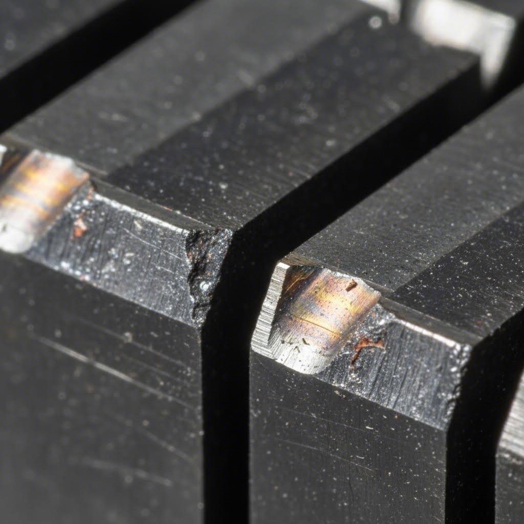
Chipping involves small fragments breaking away from the cutting edge. These chips typically measure less than 0.5mm and leave irregular, jagged edges behind. Light chipping might be acceptable initially, but it accelerates further damage as stress concentrations form around the chip boundaries. Chipping usually indicates that your carbide grade lacks sufficient toughness for the application's impact levels.
Cracking represents a more serious condition. Cracks propagate through the carbide body, sometimes visible on the surface, sometimes hidden internally until catastrophic failure occurs. Thermal cracks typically form perpendicular to the cutting edge, caused by rapid heating and cooling cycles. Mechanical cracks follow stress concentration points and may propagate at angles related to the loading direction.
Catastrophic failure occurs when the insert fractures completely, often damaging the die body and potentially the press itself. This failure mode should never occur in a well-managed operation. If you're experiencing catastrophic failures, something is fundamentally wrong with your grade selection, setup, or operating parameters.
Warning Signs That Demand Attention
Experienced operators develop an almost intuitive sense for when tooling needs attention. But relying solely on intuition risks missing problems until they affect quality. Establish systematic monitoring that catches issues early.
Watch for these warning indicators that suggest your carbide cutter inserts need evaluation:
- Burr height increase: When previously clean edges start showing noticeable burrs, your cutting edges have worn beyond optimal sharpness
- Dimensional drift: Parts trending toward tolerance limits indicate progressive wear affecting cut geometry
- Increased cutting forces: If your press seems to be working harder, worn inserts require more force to shear material
- Surface finish degradation: Rougher cut surfaces or visible scratches suggest edge damage or material buildup
- Noise changes: Sharper impacts, grinding sounds, or irregular rhythms often precede visible problems
- Material sticking: Workpiece material adhering to insert surfaces accelerates wear and affects part quality
- Visual edge damage: Any visible chips, cracks, or unusual wear patterns warrant immediate investigation
Establishing baseline measurements when inserts are new gives you reference points for comparison. Track burr height, part dimensions, and cutting force readings at regular intervals. Plotting these values over time reveals wear trends that help you schedule maintenance proactively rather than reactively.
Preventing Chipping Cracking and Premature Wear
Most premature failures trace back to identifiable root causes. Address these underlying issues, and your replacement carbide tips for lathe tools and stamping inserts alike will deliver their full service life potential.
Improper grade selection remains the most common cause of premature failure. Using a hard, low-cobalt grade in an application with significant impact loading virtually guarantees chipping. Conversely, selecting a tough, high-cobalt grade for pure abrasive wear conditions sacrifices tool life unnecessarily. Review the grade selection principles from earlier sections and honestly evaluate whether your current inserts match your actual operating conditions.
Misalignment creates uneven loading that concentrates stress on one portion of the cutting edge. Even small misalignments multiply over millions of cycles, causing localized wear or edge damage. Check punch-to-die alignment regularly using precision measurement tools. Worn guide components, loose retainers, or thermal expansion differences can all introduce misalignment that wasn't present during initial setup.
Inadequate lubrication accelerates both wear and heat buildup. Dry cutting edges experience dramatically higher friction, generating temperatures that can cause thermal cracking in carbide. Ensure your lubrication system delivers consistent coverage to all cutting surfaces. Check for clogged nozzles, depleted reservoirs, or lubricant breakdown that might compromise protection.
Excessive press speed increases impact severity and heat generation simultaneously. If you've recently increased production speed without reconsidering your carbide grade, you may have outpaced your inserts' capabilities. Higher speeds often justify upgrading to tougher grades even if the original selection worked perfectly at lower speeds.
Prevention strategies that extend tool life include:
- Regular alignment verification: Check punch-to-die clearances and concentricity at scheduled intervals, not just when problems appear
- Lubrication system maintenance: Clean, calibrate, and verify lubricant delivery systems as part of routine die maintenance
- Material inspection: Incoming material variations in thickness, hardness, or surface condition affect insert wear. Reject out-of-spec material before it damages tooling
- Proper break-in: New inserts benefit from running at reduced speed initially, allowing microscopic edge conditioning before full production demands
- Temperature monitoring: Excessive heat indicates inadequate lubrication or excessive speed. Address thermal issues before they cause cracking
Regrinding Versus Replacement Decisions
When your inserts show wear, you face a choice: regrind to restore the cutting edge or replace with new components. Both options have their place, and making the right call affects both cost and performance.
Regrinding makes economic sense when:
- Wear is uniform and confined to the cutting edge area
- Sufficient material remains to restore original geometry with acceptable tolerance
- No cracks, deep chips, or structural damage exists
- Your shop has access to proper carbide grinding equipment and expertise
- The insert design allows for multiple regrinds before retirement
Replacement becomes necessary when:
- Cracks or deep chips compromise structural integrity
- Previous regrinds have consumed available material
- Wear patterns indicate grade mismatch requiring different material
- Regrinding costs approach replacement costs
- Critical applications demand the consistency of new inserts
Most carbide inserts for stamping dies can be reground three to five times before dimensional constraints prevent further restoration. Track each insert's regrind history to know when retirement becomes inevitable. Some shops mark inserts with punch dots or etch marks to indicate regrind count visually.
Expected Tool Life Benchmarks
What constitutes reasonable tool life varies enormously based on application type. These general benchmarks help you evaluate whether your inserts are performing appropriately:
| Application Type | Typical Strokes Between Service | Factors Affecting Life |
|---|---|---|
| Light-gauge steel blanking | 500,000 - 2,000,000 | Material hardness, lubrication quality |
| Heavy-gauge steel blanking | 200,000 - 750,000 | Tonnage requirements, impact severity |
| Stainless steel piercing | 150,000 - 500,000 | Galling tendency, lubrication effectiveness |
| Aluminum stamping | 750,000 - 3,000,000 | Adhesion control, edge sharpness maintenance |
| High-strength alloy forming | 100,000 - 300,000 | Material strength, press tonnage margin |
If your actual tool life falls significantly below these ranges, investigate the root causes discussed above. Conversely, if you're substantially exceeding these benchmarks, you may have opportunities to optimize by selecting harder grades that offer even longer wear life.
Tracking actual performance against expected benchmarks reveals optimization opportunities. Perhaps your progressive die's forming station consistently underperforms expectations, suggesting a grade upgrade. Maybe your blanking punches exceed predictions, indicating you could reduce costs by extending service intervals.
With failure modes understood and prevention strategies in place, the remaining question concerns quality at the source. The manufacturing processes used to create your carbide inserts fundamentally determine their performance potential, making supplier evaluation a critical component of your tooling strategy.
Manufacturing Quality Factors and Supplier Evaluation
You've mastered grade selection, understood failure modes, and developed maintenance strategies that extend tool life. But here's a reality that often gets overlooked: two inserts with identical specifications on paper can perform dramatically differently in your dies. The difference comes down to manufacturing quality, and not all carbide inserts manufacturers produce components with equal precision.
Understanding how carbide inserts are made helps you ask the right questions when evaluating potential suppliers. The manufacturing journey from raw powder to finished insert involves multiple critical steps, and quality variations at any stage affect your tooling performance.
Sintering Grinding and EDM Finishing Quality Factors
The production of carbide inserts begins long before any machining occurs. Powder preparation sets the foundation for everything that follows. Tungsten carbide powder must be precisely milled to achieve consistent grain size distribution. Cobalt binder powder requires careful blending to ensure uniform dispersion throughout the mixture. Any inconsistency at this stage creates weak spots or hard spots in the finished product.
Powder pressing transforms the blended powder into a "green" compact that holds its shape but lacks strength. The pressing operation must apply uniform pressure across the entire insert geometry. Uneven pressure creates density variations that persist through sintering, producing inserts with inconsistent hardness across their surfaces. Premium carbide inserts suppliers invest in high-precision pressing equipment and carefully calibrated dies to ensure density uniformity.
Sintering represents perhaps the most critical manufacturing step. During sintering, the pressed compact heats to temperatures where the cobalt binder melts and flows around the tungsten carbide particles, bonding everything into a solid mass. Temperature control during this process must be exceptionally precise.
Consider what happens with temperature variations:
- Too low: Incomplete bonding leaves porosity and weak grain boundaries
- Too high: Excessive grain growth reduces hardness and edge retention
- Uneven heating: Creates internal stresses that cause cracking during use or finishing
- Improper cooling rate: Induces thermal stresses or microstructural inconsistencies
Reputable manufacturers maintain sintering furnaces with temperature uniformity within a few degrees across the entire working zone. They use controlled atmospheres to prevent oxidation and employ precise ramp rates during both heating and cooling cycles. These details rarely appear in product specifications, but they fundamentally determine insert quality.
Grinding operations transform sintered blanks into finished inserts with precise geometries. Carbide's extreme hardness demands diamond grinding wheels and rigid machine tools. The grinding process itself generates significant heat, and improper technique can induce surface cracks or residual stresses that compromise performance.
Quality-focused grinding operations feature:
- Diamond wheels dressed to precise profiles for consistent geometry
- Adequate coolant flow to prevent thermal damage
- Multiple passes with progressively finer grits for optimal surface finish
- In-process measurement to verify dimensional accuracy
EDM (Electrical Discharge Machining) finishes complex geometries that grinding cannot achieve. Wire EDM and sinker EDM create intricate profiles, tight internal corners, and features impossible to grind conventionally. However, EDM leaves a recast layer on the machined surface that can harbor micro-cracks and residual stresses.
Premium carbide inserts distributor operations either remove this recast layer through subsequent finishing or control EDM parameters to minimize layer thickness. Skipping this step leaves inserts vulnerable to premature cracking, particularly in high-stress stamping applications.
What to Look for When Evaluating Carbide Suppliers
When sourcing carbide inserts for stamping dies, you're not just buying a product; you're partnering with a manufacturer whose quality practices directly affect your production outcomes. Use this evaluation checklist to assess potential suppliers systematically:
Certifications and Quality Systems:
- ISO 9001 certification: Demonstrates documented quality management systems are in place
- IATF 16949 certification: Essential for automotive industry suppliers, indicates stringent quality controls
- Statistical process control (SPC): Shows the supplier monitors production processes, not just final products
- Traceability systems: Allows tracking of materials and processes for each batch or lot
Technical Capabilities:
- In-house powder production or verified supply chain: Controls quality from the earliest manufacturing stages
- Modern sintering equipment: Ensures precise temperature control and atmosphere management
- Precision grinding capacity: CNC grinding centers with sub-micron positioning capability
- EDM capabilities: Wire and sinker EDM for complex geometries with proper recast layer management
- Metrology equipment: CMMs, optical comparators, surface profilometers for comprehensive inspection
Quality Control Processes:
- Incoming material inspection: Verification of powder specifications before production
- In-process measurements: Dimensional checks during manufacturing, not just final inspection
- Hardness testing: Verification of HRA values on finished products
- Surface finish measurement: Quantified Ra values rather than subjective visual assessment
- Crack detection: Dye penetrant or other methods to identify surface defects
Service and Support Indicators:
- Technical consultation: Willingness to discuss grade selection and application optimization
- Custom capabilities: Ability to produce non-standard geometries or specifications
- Responsive communication: Prompt answers to technical questions and quick quotations
- Sample programs: Willingness to provide test samples for evaluation
- Failure analysis support: Assistance investigating premature failures
Why Tolerances and Surface Finish Matter
For stamping applications specifically, two quality factors deserve special emphasis: dimensional tolerances and surface finish.
Tight tolerances ensure your inserts fit precisely into their mounting locations without shimming, adjustment, or forced fitting. Loose tolerances require time-consuming fitting during die assembly and can allow micro-movement during operation that accelerates wear. Precision stamping operations typically require insert tolerances of plus or minus 0.005mm or tighter on critical dimensions.
Ask potential suppliers about their standard tolerances and their capability for tighter specifications when needed. A supplier who quotes plus or minus 0.025mm as standard may not have the equipment or expertise to deliver stamping-grade precision.
Surface finish quality affects both performance and longevity. Smoother surfaces reduce friction during material flow, minimizing adhesion problems with materials like aluminum. They also eliminate stress concentration points where cracks might initiate. For cutting edges, surface finish below Ra 0.4 microns typically delivers optimal results.
Request documentation of surface finish specifications rather than accepting vague descriptions like "ground finish" or "polished." Quantified Ra values provide objective comparison between suppliers and ensure you receive consistent quality across orders.
Evaluating suppliers carefully pays dividends throughout your tooling's service life. The premium you might pay for quality-focused carbide inserts manufacturers often returns multiple times over through extended tool life, reduced downtime, and consistent part quality. As stamping technology continues advancing, supplier capabilities in emerging technologies become increasingly important differentiators.

Emerging Technologies and Industry-Specific Applications
The carbide inserts running in your stamping dies today represent decades of metallurgical refinement, but innovation never stops. Manufacturers are pushing material science boundaries to deliver inserts that last longer, cut cleaner, and perform reliably in increasingly demanding applications. Understanding these emerging technologies helps you make forward-looking decisions when specifying tooling for new projects.
From nano-grain carbide formulations to advanced surface coatings, the next generation of carbide inserts design promises significant performance improvements. Let's explore the technologies reshaping what's possible in stamping die applications.
Nano-Grain Carbides and Next-Generation Coatings
Remember how grain size affects insert performance? Nano-grain carbides take that principle to its extreme, using tungsten carbide particles smaller than 0.5 microns to achieve remarkable property combinations. These ultra-fine structures pack more densely than conventional grades, delivering hardness values approaching 94 HRA while maintaining reasonable toughness levels.
What does this mean practically? Imagine custom carbide inserts that hold their cutting edge three to four times longer than standard grades in abrasive applications. The tighter grain structure resists the micro-chipping that gradually dulls conventional edges, maintaining sharp geometry through extended production runs. For precision stamping where burr-free edges and tight tolerances matter, nano-grain technology offers compelling advantages.
The trade-offs haven't disappeared entirely. Nano-grain carbides still sacrifice some impact resistance compared to coarser formulations, and they command premium pricing. However, for high-volume applications where extended tool life justifies higher upfront costs, these materials increasingly make economic sense.
Surface coatings represent another major advancement. Rather than changing the bulk carbide composition, coatings apply thin layers of extremely hard materials to the insert surface. Two primary technologies dominate stamping applications:
- PVD (Physical Vapor Deposition) coatings: Applied at lower temperatures, preserving the substrate's hardness. Common materials include titanium nitride (TiN), titanium aluminum nitride (TiAlN), and chromium nitride (CrN). These coatings excel at reducing friction and preventing material adhesion.
- CVD (Chemical Vapor Deposition) coatings: Applied at higher temperatures, creating thicker, more wear-resistant layers. Titanium carbide and aluminum oxide coatings provide exceptional abrasion resistance for the most demanding applications.
Coated round carbide inserts particularly benefit applications where adhesion causes problems. Aluminum stamping, for instance, sees dramatic improvements with properly selected coatings that prevent material buildup on cutting edges. The smooth, low-friction coating surface makes it much harder for soft metals to stick and accumulate.
Interestingly, coating technology has matured significantly from its origins in metalcutting applications. Techniques originally developed for woodturning carbide inserts and machining tools now transfer successfully to stamping applications, adapted for the specific stress patterns and wear mechanisms that stamping creates.
Industry-Specific Innovations in Automotive and Electronics Stamping
Different industries drive unique innovation priorities based on their specific challenges. Automotive stamping pushes development in one direction, while electronics manufacturing demands entirely different capabilities.
Automotive stamping increasingly works with advanced high-strength steels (AHSS) and ultra-high-strength steels (UHSS) that enable lighter, safer vehicle structures. These materials punish conventional tooling, requiring carbide grades specifically formulated to withstand their extreme hardness and abrasiveness. Carbide round insert geometries optimized for these applications feature specialized edge preparations that balance sharpness with impact resistance.
The automotive industry also demands exceptional consistency across massive production volumes. A single vehicle model might require stamped components numbering in the millions annually, with zero tolerance for quality variation. This environment drives continuous improvement in carbide insert consistency, with manufacturers investing heavily in process controls that ensure batch-to-batch uniformity.
Successfully integrating advanced carbide technology into automotive stamping dies requires sophisticated engineering support. Companies like Shaoyi demonstrate how advanced engineering capabilities, including CAE simulation and IATF 16949 certification, support optimal carbide insert integration. Their approach to precision stamping die solutions leverages rapid prototyping capabilities and achieves a 93% first-pass approval rate, indicators of sophisticated die design that maximizes carbide insert performance from the very first production run.
Appliance manufacturing emphasizes different priorities. Here, cosmetic surface quality often matters as much as dimensional accuracy. Visible stamped components must emerge without scratches, mars, or surface defects that would require secondary finishing. This drives development of polished carbide surfaces and specialized coatings that minimize any marking of the workpiece.
Additionally, appliance stamping frequently involves stainless steel and coated steels where maintaining surface finish integrity challenges conventional tooling. Custom carbide inserts with mirror-polished working surfaces address these demands, though they require careful handling and specialized maintenance procedures.
Electronics stamping operates at scales that make automotive production look modest. Connector terminals, lead frames, and micro-stamped components number in the billions annually. The miniaturization trend creates unique challenges for carbide inserts:
- Micro-geometry precision: Features measuring fractions of a millimeter demand insert tolerances approaching one micron
- Edge sharpness: Thin materials require exceptionally keen edges to shear cleanly without deformation
- Heat management: High-speed stamping of thin materials generates concentrated heat at microscopic cutting edges
- Material variety: Copper alloys, specialty metals, and plated materials each require optimized carbide selection
Nano-grain carbides particularly benefit electronics stamping, where their exceptional edge retention maintains the sharp geometries these tiny features demand. The premium pricing becomes easier to justify when a single insert station might produce tens of millions of components before requiring service.
Looking Ahead
The technologies emerging today will become standard practice tomorrow. Shops that stay informed about these developments position themselves to adopt improvements as they mature, maintaining competitive advantages in quality, cost, and capability. Whether your operation focuses on automotive components, appliance housings, or electronic connectors, understanding how carbide insert technology continues evolving helps you make smarter tooling decisions for years to come.
Frequently Asked Questions About Carbide Inserts for Stamping Dies
1. How to choose the right carbide insert for stamping dies?
Selecting the right carbide insert depends on five key factors: workpiece material, cobalt binder percentage (6-15%), grain size classification, stamping application type, and production volume. For abrasive materials like steel, choose harder grades with 6-8% cobalt. For high-impact applications or stainless steel stamping, opt for tougher grades with 10-12% cobalt content. Match submicron grain sizes for precision blanking and coarser grains for heavy blanking operations.
2. How long do carbide inserts typically last in stamping applications?
Carbide insert lifespan varies significantly by application. Light-gauge steel blanking typically achieves 500,000 to 2,000,000 strokes between service. Heavy-gauge steel blanking ranges from 200,000 to 750,000 strokes. Stainless steel piercing yields 150,000 to 500,000 strokes, while aluminum stamping can reach 750,000 to 3,000,000 strokes. Factors affecting longevity include material hardness, lubrication quality, press speed, and proper grade selection.
3. What is the difference between carbide and cermet inserts for stamping?
Carbide inserts use tungsten carbide particles bonded with cobalt, offering excellent wear resistance and toughness for most stamping operations. Cermet inserts combine ceramic and metallic materials, providing superior performance in heavy-duty operations with tough, abrasive materials. For typical metal stamping dies, carbide remains the preferred choice due to its balanced properties, while cermet suits specialized applications requiring extreme hardness.
4. What are the disadvantages of using carbide inserts in stamping dies?
Carbide inserts have higher upfront costs compared to tool steel alternatives, typically 5-10 times more expensive. They require specialized diamond grinding equipment for resharpening and have lower tensile strength than high-speed steel. Carbide is also more brittle than tool steel, making it susceptible to chipping under severe impact loading if the wrong grade is selected. However, the extended tool life often offsets these disadvantages in high-volume production.
5. When should I replace versus regrind carbide inserts?
Regrind carbide inserts when wear is uniform and confined to cutting edges, sufficient material remains for geometry restoration, and no structural damage exists. Replace inserts when cracks or deep chips compromise integrity, previous regrinds have consumed available material, or wear patterns indicate grade mismatch. Most stamping carbide inserts can be reground 3-5 times before retirement. Track each insert's regrind history to optimize replacement timing.