 Small batches, high standards. Our rapid prototyping service makes validation faster and easier —

Aluminum Sheet Metal Fabrication: From Alloy Selection To Final Finish
What Makes Aluminum Sheet Metal Fabrication Essential
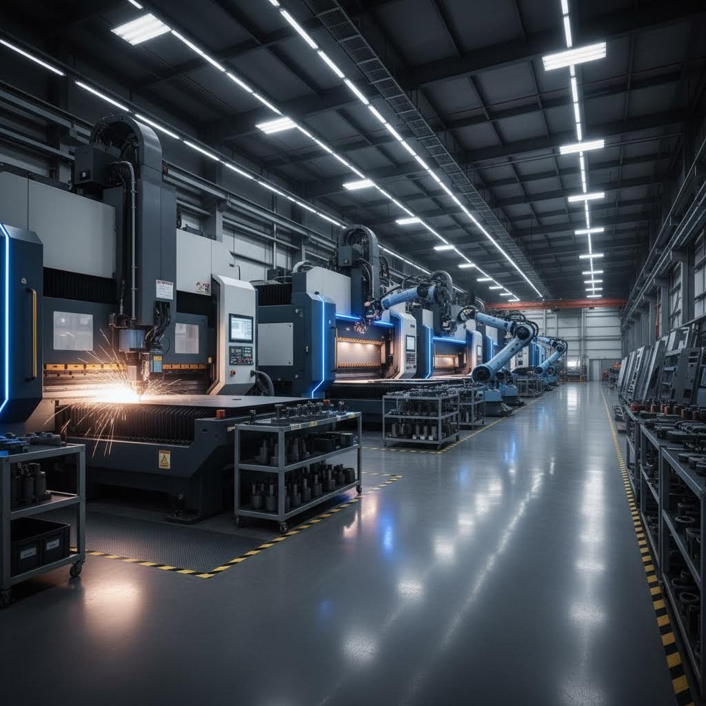
When you think about the products shaping modern life—from sleek electronics enclosures to aircraft components—you're often looking at the results of aluminum sheet metal fabrication. This versatile manufacturing process has become a cornerstone of industries worldwide, enabling engineers and designers to transform flat aluminum sheets into precisely engineered components that power everything from your smartphone to commercial aircraft.
Aluminum sheet metal fabrication encompasses the cutting, forming, joining, and finishing of thin aluminum sheets into functional components used across aerospace, automotive, electronics, and construction industries.
But what makes this particular metal sheet so universally preferred? The answer lies in aluminum's remarkable combination of properties that no other material can quite match.
Why Aluminum Dominates Modern Manufacturing
Is aluminum a metal worth all the attention it receives? Absolutely—and the numbers prove it. According to Metal Supermarkets, an aluminum structure typically weighs half as much as a steel structure while carrying the same load. This exceptional strength-to-weight ratio makes aluminum fabrication indispensable in aerospace, motorsport, and any application where reducing weight translates directly to improved performance.
Consider these standout advantages that drive aluminum's dominance:
- Natural corrosion resistance: Unlike steel components that readily rust in damp environments, aluminum sheet materials remain impervious to corrosion even after prolonged exposure to the elements
- Excellent formability: Aluminum's malleability allows fabricators to create complex shapes through bending, stamping, and deep drawing without cracking
- Superior recyclability: Aluminum requires significantly less energy to melt and reprocess, with recycled cans typically containing around 70% recycled material
- Thermal and electrical conductivity: These properties make aluminum ideal for heat sinks, electrical enclosures, and thermal management applications
The Fabrication Process at a Glance
Understanding metal fabrication starts with recognizing the four fundamental stages that transform raw aluminum sheet into finished components. Each stage requires specialized equipment and expertise to achieve optimal results.
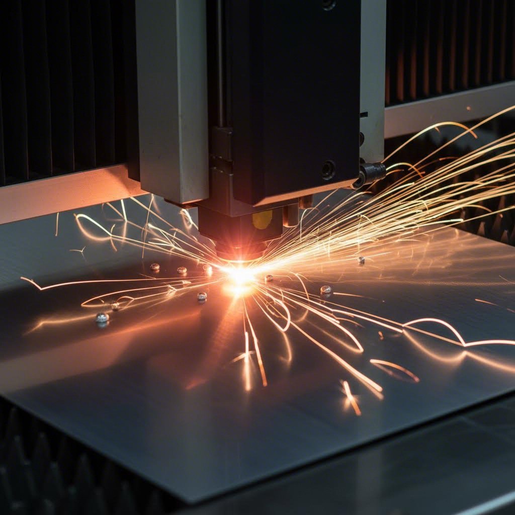
Cutting initiates the process, where techniques like laser cutting, plasma cutting, and CNC routing shape the aluminum to initial specifications. Laser cutting, in particular, utilizes a focused beam to melt or vaporize material with exceptional precision—ideal for intricate designs and tight tolerances.
Forming follows, employing press brakes, stamping dies, and roll forming equipment to bend and shape flat sheets into three-dimensional components. This stage demands careful consideration of bend radii and material grain direction.
Joining brings individual pieces together through welding, riveting, or adhesive bonding. The joining method you select depends on strength requirements, appearance needs, and production volume.
Finishing completes the transformation, applying anodizing, powder coating, or other surface treatments that enhance both durability and aesthetics.
This comprehensive guide bridges the gap between basic understanding and practical application. You'll discover how to select the right alloy for your project, choose appropriate gauges, optimize designs for manufacturability, and avoid common pitfalls that drive up costs and delay production. Whether you're an engineer specifying your first aluminum component or a procurement specialist evaluating fabrication partners, the insights ahead will equip you to make informed decisions at every step.
Aluminum Alloy Selection for Fabrication Success
Choosing the right aluminum alloy can make or break your fabrication project. With dozens of alloys available, how do you determine which one delivers the performance you need without driving up costs? The answer starts with understanding the numbering system that categorizes every aluminum alloy—and knowing which properties matter most for your specific application.
Understanding Aluminum Alloy Series
Aluminum alloys follow a four-digit numbering system where the first digit identifies the series and primary alloying element. Think of it as a roadmap that immediately tells you what to expect from any given alloy. Here's what each series brings to your aluminum sheet metal fabrication projects:
- 1000 Series (Pure Aluminum): Excellent corrosion resistance and high thermal conductivity, but lower strength—ideal for chemical processing and heat exchangers
- 2000 Series (Aluminum-Copper): High strength and fatigue resistance, commonly used in aerospace applications like aircraft structures
- 3000 Series (Aluminum-Manganese): Good formability with moderate strength, perfect for decorative applications, HVAC systems, and cooking utensils
- 5000 Series (Aluminum-Magnesium): Exceptional corrosion resistance and weldability, the go-to choice for marine environments and pressure vessels
- 6000 Series (Aluminum-Magnesium-Silicon): Versatile heat-treatable alloys with good machinability, widely used in structural components and architectural applications
- 7000 Series (Aluminum-Zinc): The strongest aluminium alloy options available, used extensively in aerospace and military applications where maximum strength-to-weight ratio is critical
For most aluminum alloy sheet metal projects, you'll find yourself working within the 3000, 5000, and 6000 series. These aluminum alloy sheets offer the best balance of fabrication-friendly properties and real-world performance.
The Big Three: 5052, 6061, and 3003 Compared
When fabricators reach for aluminum, three alloys dominate the conversation. Understanding their distinct personalities helps you match the right material to your application requirements.
5052 Aluminum stands out as the workhorse for marine and general fabrication applications. According to Approved Sheet Metal, 5052 aluminum sheet metal ranks among the strongest non-heat-treatable alloys available. Because it contains no copper, this alloy resists saltwater corrosion exceptionally well—making it the standard choice for boat hulls, storage tanks, and outdoor equipment. The density of aluminum 5052 sits at approximately 2.68 g/cm³, and its aluminum 5052 density provides an excellent strength-to-weight ratio for structural marine applications. When you need outstanding weldability paired with corrosion resistance, 5052 aluminium delivers consistently.
6061 Aluminum earns its reputation as the most versatile and cost-efficient alloy for general-purpose fabrication. This heat-treatable alloy offers good mechanical properties combined with excellent weldability, making it suitable for everything from bicycle frames to electrical equipment. Unlike 5052, you can strengthen 6061 through heat treatment—particularly the popular T6 temper—achieving higher tensile strength values when structural demands increase.
3003 Aluminum prioritizes formability above all else. The manganese content enhances corrosion resistance while maintaining excellent workability, making this alloy ideal for applications requiring deep drawing, spinning, or complex forming operations. You'll find 3003 in roofing panels, cooking utensils, automotive trim, and HVAC ductwork where decorative appearance matters as much as function.
Matching Alloys to Your Application
Selecting the optimal alloy requires weighing multiple factors against your project requirements. Consider these questions before specifying material:
- What environment will the part face? Marine or chemical exposure demands 5052's superior corrosion resistance
- How complex is the geometry? Intricate bends and deep draws favor 3003's exceptional formability
- Will the part carry significant loads? Structural applications benefit from 6061-T6's higher tensile strength
- Does the design require machining operations? 6061 machines more cleanly than softer alloys like 5052
- Is welding part of the assembly process? Both 5052 and 6061 weld excellently, while some high-strength alloys like 7075 tend to crack
| Alloy | Tensile Strength (MPa) | Formability Rating | Weldability | Corrosion Resistance | Best Applications |
|---|---|---|---|---|---|
| 3003-H14 | 150 | Excellent | Excellent | Good | HVAC, decorative trim, cooking utensils, roofing |
| 5052-H32 | 230 | Excellent | Excellent | Excellent | Marine components, pressure vessels, fuel tanks |
| 6061-T6 | 310 | Good | Excellent | Good | Structural frames, automotive parts, machinery |
| 7075-T6 | 570 | Low | Low | Excellent | Aerospace structures, military equipment |
How Temper Designations Affect Fabrication
Sounds complex? The temper designation following the alloy number tells you exactly how the material has been processed—and what to expect during fabrication. Two temper systems dominate aluminum sheet metal work:
H-tempers (strain-hardened) apply to non-heat-treatable alloys like 3003 and 5052. The H32 designation indicates strain-hardened and stabilized material with moderate strength. Softer tempers like H14 offer easier forming but lower strength, while harder tempers like H38 provide maximum strength at the expense of formability.
T-tempers (heat-treated) apply to alloys like 6061 and 7075. The T6 temper represents solution heat-treated and artificially aged material—delivering peak strength. The T4 temper offers lower strength but improved formability for applications requiring significant bending before final heat treatment.
Selecting the wrong temper can lead to cracking during forming or insufficient strength in service. When specifying aluminum alloy sheets for your project, always communicate both the alloy number and temper designation to your fabrication partner. This clarity prevents costly material substitutions and ensures your parts perform as designed.
With your alloy selected, the next critical decision involves choosing the right gauge thickness—a factor that directly impacts formability, weight, cost, and structural performance.
Gauge and Thickness Selection Simplified
Ever looked at a sheet metal gauge chart and felt confused by the counterintuitive numbering? You're not alone. The gauge system puzzles many engineers and designers because it works backward—larger gauge numbers mean thinner material. Understanding this system is essential for specifying the right sheet metal thickness aluminum for your project, and getting it wrong can lead to structural failures or unnecessary costs.
Decoding Aluminum Gauge Numbers
The gauge system dates back to 19th-century metalworking practices, where thickness was measured relative to weight per square foot rather than direct linear measurement. According to Xometry, gauge numbers represent thickness based on historical drawing operations—meaning a lower gauge number corresponds to a thicker sheet, while a higher number indicates thinner material.
Here's what makes aluminum gauge sizing particularly tricky: aluminum uses the Brown & Sharpe gauge system (also called American Wire Gauge or AWG), while steel follows the Manufacturer's Standard Gauge (MSG). This means a 14 gauge steel thickness differs significantly from 14 gauge aluminum thickness. Assuming gauge numbers are interchangeable between metals is one of the most damaging specification errors in fabrication.
Consider this comparison:
- 14-gauge aluminum: Approximately 1.628 mm (0.0641 inches)
- 14-gauge steel: Approximately 1.897 mm (0.0747 inches)
That 16% difference might seem small on paper, but it translates to significant variations in weight, strength, and fabrication behavior. Always verify which gauge system applies to your material before finalizing specifications.
So how many mm is a 6 gauge? Using the aluminum AWG standard, 6-gauge aluminum measures approximately 4.115 mm (0.162 inches)—thick enough for heavy structural applications. Meanwhile, 10ga aluminum thickness comes in at roughly 2.588 mm (0.1019 inches), making it suitable for demanding industrial components.
Thickness Selection by Application Type
Choosing the right gauge involves balancing four competing factors: structural requirements, formability, weight, and cost. Here's how to think through each consideration:
Structural Integrity: Thicker gauges provide greater load-bearing capacity and rigidity. However, doubling the thickness doesn't double the strength—the relationship follows more complex engineering principles. For structural brackets and load-bearing components, 14 gauge or thicker typically provides adequate performance.
Formability: Thinner materials bend more easily and allow tighter radii without cracking. As Jeelix notes, the golden rule is straightforward: the thicker the material, the greater the minimum bend radius must be. When you bend metal, the outer surface stretches while the inner surface compresses—if the bend radius is too tight for the thickness, cracks develop.
Weight Considerations: This is where aluminum truly shines compared to steel. Because aluminum weighs roughly one-third as much as steel at equivalent volume, you can often use thicker aluminum gauges while still reducing overall component weight versus a steel alternative.
Cost Impact: Material cost increases directly with thickness, but labor costs for forming and handling thinner gauges may offset some savings. Extremely thin gauges also risk distortion during fabrication, potentially increasing scrap rates.
| Gauge | Thickness (inches) | Thickness (mm) | Weight (lbs/ft²) | Recommended Applications |
|---|---|---|---|---|
| 24 | 0.0201 | 0.511 | 0.286 | Decorative panels, signage, light enclosures |
| 22 | 0.0253 | 0.643 | 0.360 | HVAC ductwork, appliance housings |
| 20 | 0.0320 | 0.813 | 0.455 | Electronics enclosures, cabinet panels |
| 18 | 0.0403 | 1.024 | 0.573 | Automotive panels, equipment covers |
| 16 | 0.0508 | 1.291 | 0.722 | Chassis components, industrial enclosures |
| 14 | 0.0641 | 1.628 | 0.911 | Structural brackets, mounting plates |
| 12 | 0.0808 | 2.052 | 1.149 | Heavy equipment panels, load-bearing frames |
| 10 | 0.1019 | 2.588 | 1.449 | Heavy-duty structural components, armor panels |
Note: Weights based on 6061-T6 aluminum with approximate density of 0.0975 lb/in³. Values may vary slightly across different alloys.
Minimum Bend Radius Guidelines
When designing parts that require bending, the minimum bend radius becomes critical. Specify too tight a radius for your chosen thickness, and you'll encounter cracking along the bend line. As a general guideline for common aluminum alloys:
- Soft tempers (O, H14): Minimum inside bend radius equals 0.5× to 1× material thickness
- Intermediate tempers (H32, T4): Minimum inside bend radius equals 1× to 1.5× material thickness
- Hard tempers (H38, T6): Minimum inside bend radius equals 1.5× to 2× material thickness
For example, bending 14-gauge (1.628 mm) 6061-T6 aluminum requires a minimum inside radius of approximately 2.4 mm to 3.3 mm. Attempting a sharper bend risks cracking the material on the outer surface.
Understanding these gauge relationships and thickness considerations ensures you specify material that meets both structural and manufacturing requirements. With the right thickness selected, the next step involves choosing the optimal cutting and forming methods to transform your aluminum sheet into finished components.
Cutting and Forming Methods Explained
You've selected your alloy and specified the right gauge—now comes the question that shapes your entire fabrication strategy: which cutting and forming methods will deliver the precision, edge quality, and cost efficiency your project demands? The answer isn't one-size-fits-all. Each technology offers distinct advantages, and understanding these differences helps you optimize both quality and budget.
Cutting Technologies Compared
Modern aluminum sheet metal fabrication relies on four primary cutting technologies, each excelling in specific scenarios. Let's break down what makes each method unique—and when to choose one over another.
Laser Cutting dominates when precision matters most. A laser cutter focuses an intense beam of light to melt or vaporize material with surgical accuracy. For thin to medium gauge aluminum (typically up to 0.25 inches), laser cutting delivers exceptionally clean edges with minimal post-processing. The kerf width—the material removed by the cutting process—remains extremely narrow at approximately 0.006 to 0.015 inches, allowing intricate designs and tight nesting patterns that maximize material utilization.
However, aluminum's high thermal conductivity presents a unique challenge. According to Wurth Machinery, aluminum dissipates heat rapidly during cutting, requiring higher power settings and optimized parameters compared to steel. This means laser cutting aluminum demands specialized expertise to prevent burrs, dross buildup, or inconsistent edge quality.
Waterjet Cutting stands apart as the only method producing absolutely no heat-affected zone. High-pressure water mixed with abrasive particles cuts through virtually any material thickness without thermal distortion—ideal when working with heat-sensitive applications or thick aluminum plates exceeding 1 inch. The waterjet market continues growing, projected to reach over $2.39 billion by 2034, reflecting increasing demand for this versatile technology.
CNC Routing offers a cost-effective alternative for softer aluminum alloys like 3003. Because aluminum is malleable—or as some describe it, aluminium malleable—routing tools cut through the material efficiently without excessive wear. This method works particularly well for thicker sheets where laser cutting becomes impractical and when edge finish requirements are moderate.
Plasma Cutting uses an electrical arc and compressed gas to blast through conductive metals. While less precise than laser cutting, plasma excels with thicker aluminum plates where speed and economy matter more than edge perfection. Testing shows plasma cutting is approximately 3-4 times faster than waterjet on 1-inch material, with operating costs roughly half as much per foot.
| Method | Best Thickness Range | Precision Level | Edge Quality | Speed | Cost Considerations |
|---|---|---|---|---|---|
| Laser Cutting | Up to 0.25" (6mm) | ±0.005" | Excellent | Very Fast | Higher equipment cost; low operating cost for thin materials |
| Waterjet | Up to 6"+ (150mm+) | ±0.003" to ±0.005" | Excellent | Slow to Moderate | High equipment and operating costs; no secondary finishing needed |
| CNC Routing | 0.125" to 1" (3-25mm) | ±0.005" to ±0.010" | Good | Moderate | Low equipment cost; economical for softer alloys |
| Plasma | 0.25" to 2"+ (6-50mm+) | ±0.020" to ±0.030" | Fair to Good | Very Fast | Low equipment and operating costs for thick materials |
How Kerf Width Affects Your Design
Imagine designing a puzzle where every cut removes material—that's essentially what kerf does to your parts. The kerf represents the width of material consumed by the cutting process, and it varies dramatically between methods:
- Laser cutting: 0.006" to 0.015" kerf—ideal for intricate parts with tight tolerances
- Waterjet: 0.030" to 0.050" kerf—wider but consistent, requiring design compensation
- CNC routing: Dependent on tool diameter, typically 0.125" to 0.250"
- Plasma: 0.060" to 0.120" kerf—widest of all methods
When nesting multiple parts on a single sheet, narrower kerf means less wasted material between components. A laser cutter's minimal kerf allows parts to nest within fractions of an inch of each other, while plasma's wider kerf demands greater spacing—potentially reducing the number of parts per sheet by 10-15%.
Forming Methods for Aluminum Sheet
Once your parts are cut, forming processes transform flat blanks into three-dimensional components. Understanding each method helps you design parts that are both functional and economical to produce.
Press Brake Bending remains the workhorse of sheet metal forming. A metal cutter isn't the only precision tool in the shop—press brakes use matched punches and dies to create accurate bends along predetermined lines. For aluminum, operators must account for springback—the material's tendency to partially return toward its original shape after bending. Springback in aluminum typically ranges from 2-5 degrees depending on alloy and temper, requiring overbending to achieve target angles.
Roll Forming creates continuous profiles by passing sheet through sequential roller stations. This method excels for high-volume production of consistent cross-sections like channels, angles, and custom architectural profiles. Because aluminum is aluminum malleable relative to steel, roll forming operations can achieve tighter radii and more complex profiles.
Stamping and Die Cutting use shaped tooling to punch, draw, or form parts in single or progressive operations. A die cut machine delivers exceptional speed for high-volume production, producing hundreds or thousands of identical parts per hour. The initial tooling investment can be substantial, but per-part costs drop dramatically at scale.
Bending Considerations Unique to Aluminum
Successful aluminum bending requires attention to factors that don't apply equally to other metals:
- Springback compensation: Program bends 2-5 degrees beyond target angle to account for elastic recovery
- Grain direction: Bend perpendicular to the rolling direction whenever possible to minimize cracking risk
- Tooling radius: Match punch radius to minimum bend requirements established by alloy and temper
- Lubrication: Apply appropriate lubricants to prevent galling and tool marks on soft aluminum surfaces
The interplay between cutting and forming determines not just part quality but also production efficiency and cost. Selecting methods that complement each other—like laser cutting for precision blanks followed by press brake forming—creates a streamlined workflow that minimizes handling and secondary operations.
With your cutting and forming strategies defined, the next critical consideration involves joining those formed components together—a process where aluminum's unique properties demand specialized welding expertise and techniques.
Welding and Joining Aluminum Successfully
So you've cut and formed your aluminum components—now comes the moment of truth. How do you join those pieces together without compromising the material properties you've worked so hard to preserve? Aluminum welding presents challenges that catch many fabricators off guard, and understanding these hurdles before striking an arc separates professional results from costly failures.
Unlike steel welding, where a competent welder can pick up the torch and produce acceptable results, aluminum demands specialized knowledge and AWS-certified welders who understand this metal's unique behavior. The stakes are high: improperly welded aluminum components can fail catastrophically in structural and safety-critical applications.
Why Aluminum Welding Requires Specialized Expertise
Three fundamental challenges make aluminum welding distinctly different from working with steel or stainless materials. Master these, and you'll produce strong, clean welds consistently.
The Oxide Layer Problem: According to YesWelder, aluminum has a strong affinity for oxygen—the moment pure aluminum contacts air, an oxide layer begins forming on its surface. Here's the critical issue: pure aluminum melts at approximately 1200°F (650°C), while aluminum oxide melts at a staggering 3700°F (2037°C). Attempting to weld through this oxide layer without proper removal results in inclusions, weak joints, and potential failure.
Excessive Thermal Conductivity: Aluminum conducts heat approximately five times faster than steel. When you input heat via the welding arc, that energy rapidly dissipates into surrounding material. This means the welded area becomes increasingly hotter as you progress through the joint, requiring continuous amperage adjustment. Start a weld requiring 150 amps, and by mid-joint, you may need significantly less input to avoid burn-through.
Porosity Susceptibility: As TWI Global explains, porosity in aluminum welds stems from hydrogen absorption. Hydrogen has high solubility in molten aluminum but much lower solubility—approximately 20 times lower—in solid aluminum. As the weld pool cools, hydrogen evolves and forms gas bubbles that become trapped as pores. These contaminants originate from hydrocarbons like grease and oils, moisture on surfaces, or inadequate shielding gas coverage.
TIG vs MIG for Aluminum Applications
When debating mig vs tig welding for aluminum, the choice ultimately depends on your priorities: precision versus production speed. Both processes deliver acceptable results when executed properly, but each excels in specific scenarios.
TIG Welding (GTAW) earns its reputation as the precision method for aluminum. The process uses a non-consumable tungsten electrode with separate filler rod addition, giving welders complete control over heat input and weld pool manipulation. For thin aluminum sheet metal—think electronics enclosures or decorative components—TIG delivers unmatched aesthetic quality with minimal distortion.
Critical to TIG aluminum welding is the use of alternating current (AC). The AC cycle switches between electrode-positive and electrode-negative polarities many times per second. During the electrode-positive portion, the arc strips oxides from the aluminum surface through a cleaning action. The electrode-negative portion provides deep penetration into the base metal. Quality TIG machines offer AC balance adjustment, typically between 15-85%, letting you fine-tune the cleaning-to-penetration ratio for specific applications.
MIG Welding (GMAW) trades some precision for significantly faster production speeds. The process feeds aluminum wire continuously through the gun, acting as both electrode and filler metal. For thicker sections and high-volume production runs, MIG aluminum welding proves considerably more economical than TIG.
When considering tig vs mig welding for your project, evaluate these factors:
- Material thickness: TIG excels below 1/8"; MIG handles 1/8" and above more efficiently
- Production volume: Low-volume or prototype work favors TIG; production runs favor MIG
- Aesthetic requirements: Visible welds demand TIG's superior appearance
- Welder skill level: MIG has a gentler learning curve than TIG
- Access constraints: TIG torches maneuver into tighter spaces than MIG guns with spool assemblies
Avoiding Common Welding Defects
Preventing defects starts long before you strike an arc. Proper preparation makes the difference between structural integrity and costly rework. Follow these critical pre-weld steps:
- Thorough degreasing: Remove all oils, grease, and contaminants using acetone or similar solvent cleaner—any hydrocarbon residue releases hydrogen into the weld pool
- Oxide layer removal: Use a dedicated stainless steel wire brush (never used on other metals) or specialized grinding wheels to mechanically remove the oxide layer immediately before welding
- Proper filler rod selection: Match filler alloy to base metal—ER4043 offers excellent fluidity and crack resistance, while ER5356 provides higher tensile strength and better color match for post-weld anodizing
- 100% argon shielding gas: Unlike steel MIG welding that uses CO2/argon mixtures, aluminum requires pure argon (or argon/helium blends for thick sections) to prevent contamination
- Equipment cleanliness: Use aluminum-dedicated liners, drive rolls, and contact tips to prevent cross-contamination from other materials
Environmental factors also influence weld quality. TWI Global recommends keeping aluminum welding operations separate from steel fabrication areas, as airborne particles and grinding dust can contaminate joints. Humidity introduces moisture that breaks down in the arc plasma, releasing hydrogen into the weld pool.
Alloy Weldability: Why 5052 Leads the Pack
Not all aluminum alloys weld equally. The 5052 alloy stands out as exceptionally weldable because it contains no copper—an element that increases crack susceptibility during solidification. Combined with its excellent corrosion resistance, 5052 becomes the default choice for marine applications, fuel tanks, and pressure vessels where weld integrity is paramount.
In contrast, high-strength aerospace alloys like 7075 present significant welding challenges. The zinc and copper content makes these alloys prone to hot cracking, and welding often reduces strength in the heat-affected zone. For components requiring 7075's exceptional strength, alternative joining methods typically prove more reliable.
Alternative Joining Methods
Welding isn't always the optimal solution. When thermal distortion is unacceptable, when dissimilar materials must join, or when field assembly is required, consider these alternatives:
Rivets provide excellent fatigue resistance and require no heat input—making them standard in aerospace applications where thermal distortion would compromise tolerances. Solid aluminum rivets or blind rivets enable strong, repeatable joints without specialized welding equipment.
Adhesive bonding distributes stress across entire joint surfaces rather than concentrating loads at weld points. Modern structural adhesives achieve impressive strength while providing vibration damping and galvanic isolation between dissimilar metals.
Mechanical fastening using bolts, screws, or clinching allows disassembly for maintenance or repair. Self-clinching fasteners designed for aluminum sheet metal create permanent, high-strength attachment points without penetrating the opposite surface.
When searching for an aluminum fabrication shop near me or aluminium fabrication near me, verify that potential partners hold appropriate welding certifications. AWS D1.2 certification specifically addresses structural aluminum welding, ensuring welders have demonstrated competency with this challenging material. For automotive and aerospace applications, additional certifications like IATF 16949 or AS9100 provide further quality assurance.
With joining methods selected and executed properly, attention turns to the final stage of fabrication: surface finishing. The right finish not only enhances appearance but dramatically extends component life through improved corrosion protection and wear resistance.
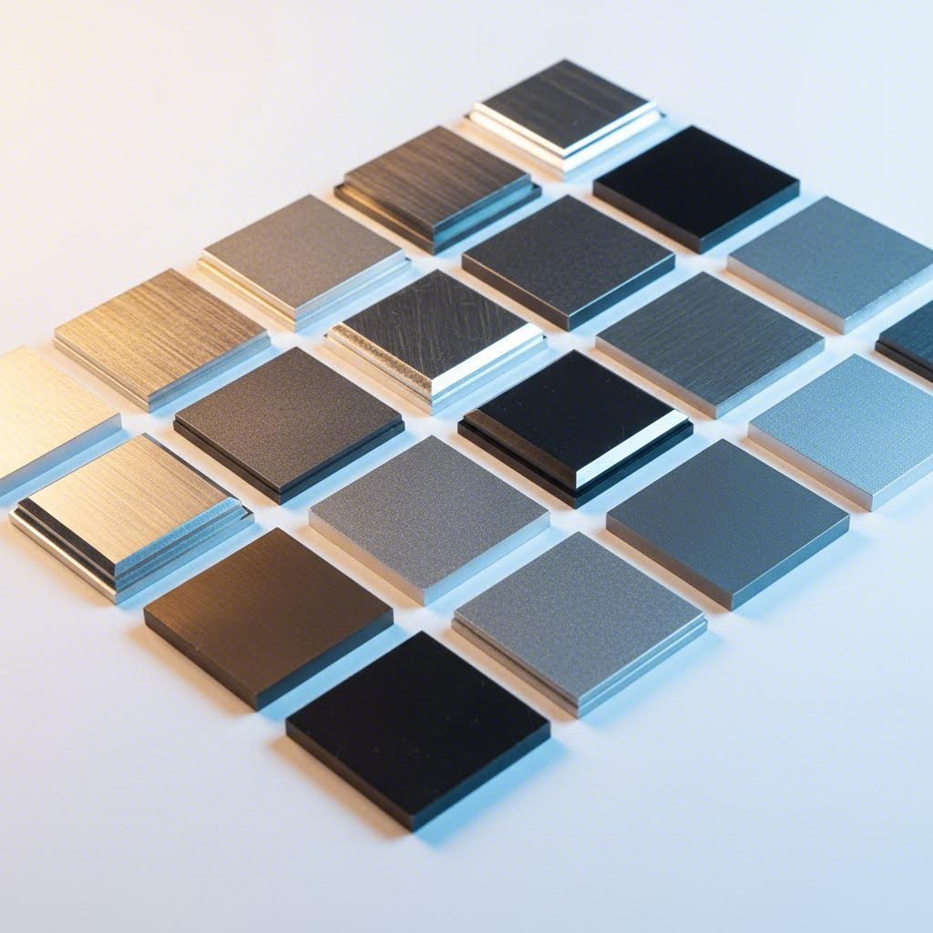
Surface Finishing Options for Aluminum Parts
Your aluminum components are cut, formed, and joined—but the fabrication journey isn't complete until you address surface finishing. This final step transforms raw aluminum into durable, aesthetically pleasing parts that resist corrosion, wear, and environmental degradation for years. Choosing the right finish impacts not just appearance but also functionality, cost, and lead times.
From anodized aluminum housings on premium electronics to powder coat finishes on architectural facades, surface treatments define how your parts perform in real-world conditions. Let's explore the options that match your project requirements.
Anodizing Types and Applications
Anodizing stands apart from other finishes because it doesn't coat the aluminum surface—it transforms it. According to Manufacturing Tomorrow, this electrochemical process thickens the naturally occurring oxide layer on aluminum, creating an integral protective barrier that won't chip, peel, or flake like applied coatings.
The process works by immersing aluminum parts in a sulfuric acid bath and applying electrical current, with the aluminum serving as the anode in the circuit. This triggers controlled oxidation that builds a hard, porous oxide layer—perfect for absorbing dyes or sealing for maximum corrosion resistance.
Type II Anodizing (Conventional/Decorative) produces an oxide layer typically ranging from 0.0001 to 0.001 inches thick. This treatment delivers:
- Vibrant color options: The porous oxide layer readily accepts dyes in virtually any color—perfect for custom metal signs, consumer electronics, and architectural elements
- Good corrosion protection: Enhanced resistance compared to bare aluminum, suitable for indoor and moderate outdoor applications
- Aesthetic metallic finish: Preserves the distinctive aluminum appearance while adding color and protection
- Cost efficiency: Lower processing costs make Type II ideal for decorative applications where extreme durability isn't required
Type III Anodizing (Hardcoat) builds significantly thicker oxide layers—typically exceeding 0.002 inches—resulting in dramatically increased hardness and wear resistance. As noted by Manufacturing Tomorrow, this makes Type III the choice for aerospace, military, and automotive components subjected to friction, abrasion, and harsh environments.
Key advantages of hardcoat anodizing include:
- Superior wear resistance: Hardness levels approaching that of hard chrome plating
- Enhanced corrosion protection: Performs in aggressive chemical and marine environments
- Electrical insulation: The thick oxide layer provides excellent dielectric properties
- Color limitations: Primarily available in clear, gray, or black, though dyes can be applied
Powder Coating: Durability Meets Design Freedom
When you need brilliant colors, unique textures, or exceptional outdoor durability, powder coating services deliver results that anodizing cannot match. According to Gabrian, this dry application process eliminates solvents entirely, making it an environmentally friendly alternative to liquid paints.
The process applies electrostatically charged powder particles to grounded aluminum parts, creating uniform adhesion before heat curing transforms the powder into a solid, continuous coating. The results speak for themselves:
- Unlimited color selection: Match any RAL or Pantone color with consistent batch-to-batch repeatability
- Texture variety: From smooth gloss to textured matte, metallic sparkle to hammered finishes
- Outstanding UV resistance: Colors resist fading even under prolonged sun exposure
- Thick, durable coating: Applied in layers up to several mils thick for impact and scratch resistance
Powder coating proves particularly popular for outdoor equipment, architectural elements, and applications where color matching across multiple components is essential. The aluminum sheet metal cost for powder-coated parts includes both material and finishing expenses, but the durability often justifies the investment through extended service life.
Chromate Conversion Coating: The Specialist Choice
Sometimes you need protection without sacrificing aluminum's natural electrical conductivity. Chromate conversion coating—also called chemical conversion coating or Alodine—creates a thin protective film that preserves conductivity while providing corrosion resistance and excellent paint adhesion.
This treatment excels in electronics applications where EMI shielding depends on metal-to-metal contact, and in situations where subsequent painting or bonding requires enhanced surface preparation. The coating appears as a light gold, clear, or olive drab finish depending on the specific chemistry used.
Choosing the Right Finish for Your Project
Your finish selection should align with application requirements, budget constraints, and aesthetic goals. Consider these industry-specific guidelines:
Architectural applications typically favor Type II anodizing for its metallic appearance and weathering durability, or powder coating when specific colors must match building design elements. Both finishes handle outdoor exposure well.
Automotive components often require Type III hardcoat anodizing for wear surfaces or powder coating for visible trim pieces. The combination of durability and appearance options makes these finishes automotive industry standards.
Electronics enclosures present unique requirements: EMI shielding demands electrical conductivity (favoring chromate conversion), while thermal management benefits from anodizing's improved heat dissipation properties.
| Finish Type | Corrosion Protection | Aesthetic Options | Conductivity | Cost Range | Best Applications |
|---|---|---|---|---|---|
| Type II Anodizing | Good | Full color range, metallic appearance | None (insulator) | Medium | Consumer products, architectural, decorative |
| Type III Anodizing | Excellent | Limited (clear, gray, black) | None (insulator) | High | Aerospace, military, high-wear components |
| Powder Coating | Excellent | Unlimited colors and textures | None (insulator) | Low to Medium | Outdoor equipment, architectural, automotive |
| Chromate Conversion | Moderate | Gold, clear, or olive drab | Preserved | Low | Electronics, paint prep, bonding surfaces |
| Brushed/Polished | Low (requires sealer) | Metallic, reflective | Preserved | Medium | Decorative, appliances, signage |
Surface Preparation: The Foundation of Quality Finishes
Regardless of which finish you select, proper surface preparation determines ultimate quality. Contamination, oxide buildup, or surface defects telegraph through any finish, creating adhesion failures or visual defects that require costly rework.
Pre-finish preparation typically includes degreasing to remove oils and machining fluids, alkaline cleaning to remove surface contamination, and deoxidizing to remove the natural oxide layer before controlled oxide formation during anodizing. Skipping or shortcutting these steps invariably leads to finish failures.
For decorative applications, brushed and polished finishes create distinctive visual effects. Brushing produces uniform linear grain patterns, while polishing achieves mirror-like reflective surfaces. Both mechanical finishes typically require clear anodizing or lacquer sealing to maintain appearance and prevent oxidation.
How Finishing Affects Cost and Lead Time
Finishing adds both time and expense to your aluminum sheet metal fabrication project. Type III hardcoat anodizing, with its thicker oxide growth and specialized process parameters, typically costs 30-50% more than Type II and extends lead times by several days. Powder coating services require curing time but often prove more economical for high-volume production runs.
When evaluating total project cost, consider that premium finishes often reduce long-term expenses through extended part life and reduced maintenance. A hardcoat anodized component lasting 15 years may prove more economical than a painted part requiring replacement every 5 years.
With surface finishing options understood, attention turns to optimizing your designs from the start—ensuring parts are not only manufacturable but cost-effective across all fabrication stages.
Design for Manufacturability Best Practices
You've selected the perfect alloy, chosen the right gauge, and identified ideal cutting and finishing methods—but none of that matters if your design can't be manufactured efficiently. Design for Manufacturability (DFM) bridges the gap between what looks good in CAD and what actually works on the shop floor. When you're aluminum sheet fabrication projects, applying these principles from the start prevents costly redesigns, reduces lead times, and keeps production costs under control.
Think of DFM as speaking the same language as your fabricator. When your design aligns with manufacturing capabilities, parts flow through production smoothly. When it doesn't, you're looking at increased scrap rates, longer cycle times, and invoices that exceed initial quotes.
DFM Principles for Aluminum Sheet Metal
Fabricating aluminum successfully requires understanding specific design constraints that differ from steel or other metals. These guidelines ensure your parts are both manufacturable and cost-effective.
Minimum Bend Radius: According to The Fabricator, the 1x Thickness = Inside Radius Rule works reliably for ductile materials like 5052-H32 aluminum. Is 5052 aluminum bendable? Absolutely—it bends similarly to mild steel, making it ideal for parts with multiple bends. However, harder tempers like 6061-T6 require larger radii (1.5x to 2x thickness) to prevent cracking. If your design specifies bend radii tighter than material thickness, consult your fabrication partner before finalizing.
Hole-to-Edge and Hole-to-Bend Distances: Features placed too close to bends distort during aluminum forming operations. The 4T rule provides reliable guidance—keep holes, slots, and tabs at least 4 times the material thickness away from bend lines. For example, thin aluminum sheet metal measuring 0.050 inches thick requires minimum 0.200-inch clearance between features and bends. Violating this rule creates awkward deformities that compromise both function and appearance.
Minimum Flange Depth: When bending in a press brake, the sheet must fully bridge across the V-die. As The Fabricator explains, with a V-die width of 6x material thickness, the shortest manufacturable flange becomes approximately 3x material thickness. Design flanges shorter than this minimum, and your fabricator simply cannot produce the part without specialized tooling or alternative processes.
Corner Relief Requirements: Where two bends intersect, corner relief cuts prevent material bunching and tearing. These small cuts or notches at bend intersections allow material to flow properly during forming. Without adequate relief, you'll see material buckling, cracking, or dimensional inaccuracies at corners.
Tolerance Expectations: Understanding realistic tolerances prevents over-specification that drives up costs. According to industry standards, flat laser-cut parts typically hold ±0.004 inches, while bent sheet metal fabrication adds approximately ±0.010 inches per bend due to material thickness variations. Specifying ±0.005 inches on a part with four bends isn't realistic—and attempting to achieve it requires time-consuming inspection and adjustment.
Design Mistakes That Increase Costs
Even experienced engineers make design choices that inadvertently inflate fabrication costs. Recognizing these common errors helps you fabricate sheet metal parts more economically:
- Insufficient bend relief: Failing to add relief cuts at bend intersections causes material to tear or buckle, requiring rework or scrapping parts entirely
- Ignoring grain direction: Rolling creates directional grain structure in aluminum sheet. Bending perpendicular to grain direction minimizes cracking risk—designing bends parallel to grain invites failure, especially in harder tempers
- Specifying unnecessarily tight tolerances: Every decimal place beyond standard precision requires additional inspection time and potential rework. Reserve tight tolerances for truly critical dimensions
- Overlooking springback compensation: Aluminum springs back 2-5 degrees after bending. Designs that don't account for this require iterative adjustments during setup, extending production time
- Creating inaccessible weld joints: As Creatingway notes, designing welds inside closed boxes is unrealistic—the torch must access the seam. Design weld locations on outside surfaces where fabricators can actually reach them
- Ignoring U-channel proportions: For U-channel designs, maintain a minimum 2:1 width-to-height ratio. Narrower channels require specialized gooseneck tooling or welded assemblies, significantly increasing cost
Complexity, Cost, and Fabrication Method Selection
Your design complexity directly influences which fabrication methods are viable—and their associated costs. Simple geometries with standard bend radii can run on conventional press brakes with off-the-shelf tooling. Complex forms may require progressive dies, specialized fixtures, or multi-stage operations that multiply setup time and expense.
Consider these relationships when evaluating design alternatives:
- Number of bends: Each additional bend adds setup time, tolerance stack-up, and potential for error. Consolidating features or using alternative geometries can reduce bend count
- Unique bend radii: Standardizing on a single bend radius throughout your design allows fabricators to complete all bends without tool changes, reducing cycle time
- Custom tooling requirements: Non-standard features like hemmed edges, offset bends, or acute angles may require custom punch and die sets—worthwhile for high-volume production but costly for prototypes
Nesting Optimization for Material Utilization
Material represents a significant portion of aluminum sheet fabrication costs. Nesting—the arrangement of flat patterns on raw sheets—determines how much material becomes finished parts versus scrap.
Design choices that improve nesting efficiency include:
- Consistent part orientation: Parts that can rotate 180 degrees without affecting function nest more efficiently
- Rectangular outer profiles: Complex outer contours create nesting gaps that increase waste
- Standardized sheet sizes: Designing parts to nest efficiently on standard 48" × 120" sheets reduces material cost compared to requiring custom sheet dimensions
Laser cutting's narrow kerf (0.006-0.015 inches) allows parts to nest within fractions of an inch of each other, maximizing yield from each sheet. When your design enables tight nesting, you benefit from lower material costs passed through by your fabricator.
Prototype Versus Production Design Considerations
What works beautifully for a one-off prototype may become prohibitively expensive at production volumes—and vice versa. Recognizing these differences helps you design appropriately for each stage:
Prototype designs can tolerate:
- Manual welding operations that skilled craftsmen execute perfectly on individual parts
- Complex geometries formed through multiple setups and careful hand adjustment
- Non-standard materials or gauges available from specialty suppliers
Production designs require:
- Consistent, repeatable processes that maintain quality across thousands of parts
- Features compatible with automated equipment and minimal operator intervention
- Materials available in production quantities from multiple sources
The transition from prototype to production often reveals design elements that worked in small quantities but don't scale. A skilled aluminum forming operation might manually compensate for insufficient bend relief on ten prototypes, but that workaround becomes unsustainable across ten thousand production parts.
By applying DFM principles from initial concept through final production release, you create designs that fabricate efficiently at any volume. This foundation of manufacturability prepares your project for the inevitable challenges that arise during actual production—challenges we'll address in the next section on troubleshooting common fabrication problems.
Common Fabrication Challenges and Solutions
Even with perfect alloy selection, precise gauge specifications, and optimized designs, aluminum fabrication can go sideways quickly. Parts warp after welding. Bends crack unexpectedly. Weld porosity appears despite careful preparation. Understanding why these problems occur—and how to prevent them—separates successful projects from costly failures.
One of the most important facts about aluminum is that it behaves differently than steel at nearly every fabrication stage. Its high thermal conductivity, lower melting point, and sensitivity to contamination create challenges that demand proactive solutions rather than reactive fixes. Let's examine the most common issues and their prevention strategies.
Preventing Warping and Distortion
Warping ranks among the most frustrating aluminum fabrication defects because it often appears after significant work has been completed. According to ESAB, welding distortion results from "the non-uniform expansion and contraction of weld metal and adjacent base metal during the heating and cooling cycle." With aluminum's thermal expansion coefficient nearly twice that of steel, this problem becomes even more pronounced.
The physics are straightforward: when you apply localized heat during welding, the heated zone expands while surrounding cool material restrains it. As the weld cools and contracts, internal stresses develop—and if those stresses exceed the material's ability to resist deformation, warping occurs.
Effective prevention strategies include:
- Minimize weld volume: Over-welding is the most common cause of excessive distortion. Use proper fillet weld gauges to ensure welds match specifications without exceeding them. A larger weld isn't a stronger weld—it's a hotter weld that causes more distortion
- Optimize joint design: Double-V-groove joints require approximately half the weld metal of single-V-groove joints, significantly reducing heat input and resulting distortion
- Balance welds around the neutral axis: Position welds near the center of gravity of the cross-section. Placing similar-sized welds on opposite sides balances shrinkage forces against each other
- Use proper fixturing and restraints: Clamps, jigs, and fixtures hold components in position during welding and cooling. Back-to-back assembly—clamping two identical weldments together before welding—allows shrinkage forces to counteract each other
- Apply backstep welding sequences: Instead of welding continuously in one direction, deposit short weld segments in the opposite direction of overall progress. This technique locks prior welds in place and distributes heat more evenly
- Consider presetting components: Deliberately offset parts before welding so that shrinkage pulls them into final position. This requires experimentation to determine correct offset amounts but produces consistently aligned assemblies
ESAB also recommends considering aluminum extrusions as an alternative to welded fabrications. Extruded sections reduce the total amount of welding required, inherently minimizing distortion potential while often improving aesthetics and assembly efficiency.
Troubleshooting Bend Failures
Cracking during bending typically signals a mismatch between material properties and forming requirements. According to Jeelix, the outer fibers of the material stretch beyond their maximum elongation capacity—an unmistakable case of localized overstressing. Understanding why cracks develop helps you prevent them before they ruin parts.
The relationship between alloy, temper, and formability proves critical here. Consulting an aluminum temper chart before specifying materials helps match temper designations to forming requirements. Softer tempers (O, H14) accommodate tighter bends, while harder tempers (H38, T6) demand larger radii to prevent failure.
Key factors that contribute to 5052 aluminum bending success—or failure—include:
- Bend radius too tight: Every material has a minimum safe bend radius. Forcing bends tighter than this threshold inevitably causes cracking
- Grain direction ignored: Bending parallel to the rolling direction stresses the material's weakest orientation. Always orient bends perpendicular to grain whenever possible
- Wrong alloy or temper selected: High-strength alloys like 7075-T6 have poor formability compared to 5052-H32. Material substitution without design adjustment causes problems
- Tooling mismatch: Using punches with radii smaller than material specifications creates stress concentrations that initiate cracks
- Surface defects: Scratches, gouges, or edge burrs from cutting operations act as crack initiation sites during bending
When cleaning aluminum oxide from surfaces before forming, use stainless steel brushes dedicated exclusively to aluminum. Cross-contamination from steel particles creates galvanic corrosion sites and can affect surface finish quality. Proper methods for clean aluminum oxidation removal include solvent cleaning followed by mechanical brushing—never use steel wool or brushes previously used on ferrous metals.
Addressing Weld Porosity
Porosity—those small gas bubbles trapped in solidified weld metal—compromises both strength and appearance. When welding 5052 aluminum or other alloys, hydrogen absorption remains the primary culprit. Hydrogen dissolves readily in molten aluminum but has roughly 20 times lower solubility in solid aluminum. As welds cool, hydrogen evolves and forms bubbles that become permanent defects.
Prevention focuses on eliminating hydrogen sources:
- Thorough cleaning: Remove all oils, grease, and hydrocarbons that release hydrogen when heated. Acetone or specialized aluminum cleaners work effectively
- Oxide removal: Use dedicated stainless steel brushes immediately before welding. The oxide layer traps moisture and contaminants that contribute to porosity
- Dry shielding gas: Moisture in argon shielding gas breaks down in the arc, releasing hydrogen. Use high-quality gas from reputable suppliers and maintain dry gas lines
- Proper gas coverage: Inadequate shielding gas flow allows atmospheric moisture to contaminate the weld pool. Verify flow rates and torch positioning
- Dry filler materials: Store filler rods and wire in climate-controlled environments. Condensation on cold filler materials introduces moisture directly into welds
Warning Signs and Root Causes
Recognizing problems early prevents scrap and rework. Watch for these indicators during production:
- Inconsistent bend angles: Indicates material thickness variation, worn tooling, or incorrect springback compensation
- Orange peel texture on bend exteriors: Material stretched near its limits—a warning sign that cracking may follow
- Excessive weld spatter: Contamination, incorrect parameters, or moisture in shielding gas
- Color variation in anodized finishes: Alloy or temper inconsistency between parts, often from mixed material batches
- Dimensional drift during production runs: Tooling wear, thermal expansion of equipment, or material property variation within coils
- Visible porosity or inclusions: Contamination, inadequate cleaning, or improper welding technique
Quality Control Checkpoints
Building quality into your process requires inspection at critical stages—not just final inspection that catches problems too late:
Incoming material inspection: Verify thickness with calibrated micrometers at multiple locations. Confirm alloy through mill certifications or portable XRF testing. Check for surface defects, edge condition, and flatness. Material that doesn't meet specifications will create problems throughout fabrication.
Post-cutting inspection: Examine edge quality for burrs, heat-affected zones, or taper that could affect subsequent operations. Verify dimensional accuracy against CAD specifications.
In-process forming checks: Measure bend angles on first articles before running production quantities. Verify flange dimensions and overall geometry against tolerances.
Weld inspection: Visual examination reveals porosity, cracks, undercut, and incomplete fusion. Dye penetrant testing detects surface cracks invisible to naked eyes. For critical applications, radiographic or ultrasonic testing provides subsurface defect detection.
Final inspection: Dimensional verification, surface finish evaluation, and functional testing as required by application.
Material Certification and Traceability
When problems occur, traceability helps identify root causes. Material certifications document alloy composition, temper, and mechanical properties at the time of manufacture. Maintaining lot traceability—knowing which material went into which parts—enables targeted investigation when defects appear.
For aerospace, automotive, and other demanding applications, certified materials with full traceability aren't optional—they're mandatory. Even for less critical applications, material documentation protects against suppliers shipping incorrect alloys or tempers that look identical but perform differently.
Environmental Factors Affecting Quality
Shop floor conditions influence fabrication outcomes more than many realize:
- Humidity: Moisture condenses on cold aluminum surfaces, introducing hydrogen into welds and affecting adhesion of coatings and adhesives
- Contamination: Airborne particles from grinding steel, cutting fluids, and general shop dust settle on aluminum surfaces. Cleaning aluminum oxide and contaminants before welding becomes critical in mixed-material shops
- Temperature: Cold aluminum requires adjusted welding parameters. Material stored below shop temperature should acclimate before fabrication
- Storage conditions: Aluminum sheet stored improperly develops surface corrosion, oil staining from packaging materials, or mechanical damage that affects finished part quality
When to Consult Fabrication Experts
Some problems exceed in-house troubleshooting capabilities. Consider seeking expert guidance when:
- Defects persist despite implementing standard corrective actions
- New alloys, tempers, or thicknesses behave unexpectedly
- Application requirements push materials near their performance limits
- Welding certifications require qualified procedures and welder testing
- Cost of continued trial-and-error exceeds cost of professional consultation
- Production deadlines don't allow time for iterative problem-solving
Experienced fabrication partners bring institutional knowledge from thousands of projects. They've seen your problem before—and they know which solutions work. That expertise becomes invaluable when timelines are tight and quality requirements are unforgiving.
With troubleshooting strategies in hand, you're prepared to tackle the challenges that inevitably arise during aluminum fabrication. The next section explores how these techniques apply across specific industries—from automotive chassis components to aerospace structures—each with unique requirements and quality standards.
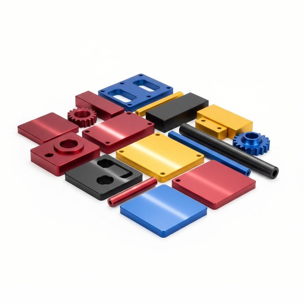
Industry Applications from Automotive to Aerospace
Where does all this aluminum sheet metal fabrication expertise actually get applied? The answer spans virtually every industry where weight, durability, and precision matter—from the car in your driveway to the aircraft crossing overhead and the smartphone in your pocket. Each industry prioritizes different aluminum properties, creating distinct fabrication requirements that shape how aluminum parts manufacturing unfolds.
Understanding these application-specific demands helps you specify materials, tolerances, and finishing requirements appropriately. What works for an architectural facade won't satisfy aerospace requirements, and consumer electronics priorities differ substantially from heavy equipment needs.
Automotive and Transportation Applications
The automotive industry has embraced fabricated aluminum with remarkable enthusiasm—and for good reason. According to the Aluminum Extruders Council, aluminum subframes deliver approximately 35% weight reduction compared to steel while achieving comparable piece prices and up to 1000% savings on tooling costs versus stamped steel frames.
Weight reduction translates directly to performance benefits that engineers and consumers both appreciate:
- Improved fuel efficiency: Every 10% reduction in vehicle weight improves fuel economy by 6-8%
- Enhanced acceleration and handling: Lower mass means quicker response to driver inputs
- Extended electric vehicle range: Battery-electric vehicles benefit significantly from aluminum's weight savings
- Reduced braking distances: Lighter vehicles stop faster with less brake wear
Chassis components, suspension brackets, and structural assemblies represent prime applications for aluminum fabricated products. Subframes—the structures connecting suspension components to the vehicle body—face considerable mechanical stresses and environmental exposure from their location near the ground. Aluminum's natural corrosion resistance proves particularly valuable here, eliminating the rust that plagues steel subframes exposed to road salt.
For electric vehicles, aluminum subframes serve dual purposes: structural support and battery protection. As noted in the Porsche Taycan's design, front subframes protect batteries during frontal crashes while rear components are engineered to break away and intrude above battery packs upon impact. This crash management capability makes aluminum essential for EV safety engineering.
Automotive aluminum parts require IATF 16949 certification from manufacturers—the quality standard that ensures chassis and suspension components meet automotive industry requirements. When development cycles demand rapid iteration, capabilities like 5-day prototyping prove invaluable for testing designs before committing to production tooling. Comprehensive DFM support helps optimize aluminum part designs, catching manufacturability issues before they become production problems.
Electronics and Aerospace Requirements
While automotive applications prioritize weight reduction and corrosion resistance, aerospace and electronics industries add stringent precision and performance requirements that push aluminum fabrication capabilities to their limits.
Aerospace applications demand the highest material certifications and tightest tolerances. According to CMT Finishing, aircraft parts face constant exposure to high-altitude UV rays, fluctuating temperatures, and moisture—conditions requiring finishing solutions that protect performance without adding unnecessary weight. Hardcoat anodizing is often specified for aerospace-grade aluminum alloys because it ensures components endure decades of service without compromising safety or reliability.
Aerospace aluminum fabrication typically involves:
- High-strength alloys: 7000-series alloys for primary structures requiring maximum strength-to-weight ratios
- Precision tolerances: Dimensional requirements measured in thousandths of an inch
- Full material traceability: Documentation tracking each component back to original material lots
- Specialized joining: Riveting often preferred over welding for fatigue-critical applications
- Type III hardcoat anodizing: Superior wear and corrosion protection for critical components
Electronics enclosures present unique challenges where EMI shielding and thermal management drive material and design decisions. As CMT Finishing explains, housings and enclosures must resist wear and abrasion while heat sinks benefit from anodizing's ability to improve thermal dissipation. The combination of lightweight construction and excellent thermal conductivity makes aluminum the default choice for machining aluminum parts destined for electronics applications.
Key electronics applications include:
- Server chassis and rack enclosures: Combining structural rigidity with heat dissipation
- Consumer electronics housings: Aesthetic appeal paired with durability and EMI shielding
- Heat sinks and thermal management: Maximizing surface area while minimizing weight
- RF shielding enclosures: Preserving electrical conductivity through chromate conversion coating
How Industries Prioritize Aluminum Properties
Different industries weight aluminum's characteristics according to their specific requirements. Understanding these priorities helps you specify materials and processes appropriately:
| Industry | Primary Priorities | Typical Alloys | Common Finishes | Critical Requirements |
|---|---|---|---|---|
| Automotive | Weight reduction, crash performance, corrosion resistance | 5052, 6061, 6063 | Powder coating, E-coat | IATF 16949 certification, rapid prototyping capability |
| Aerospace | Strength-to-weight ratio, fatigue resistance, precision | 2024, 7075, 6061 | Type III anodizing, chromate conversion | AS9100 certification, full traceability |
| Electronics | Thermal management, EMI shielding, aesthetics | 5052, 6061, 3003 | Type II anodizing, brushed finish | Tight tolerances, surface finish quality |
| Marine | Corrosion resistance, weldability, durability | 5052, 5086, 6061 | Type II anodizing, paint | Saltwater corrosion testing |
| Architecture | Aesthetics, weather resistance, formability | 3003, 5005, 6063 | Anodizing, PVDF coating | Color consistency, long-term weathering |
When searching for an aluminium parts manufacturer or custom aluminum fabricators capable of serving your industry, verify that potential partners understand these specific requirements. A fabricator experienced in architectural applications may not hold the certifications required for automotive or aerospace work—and vice versa.
Finding the Right Manufacturing Partner
Industry-specific requirements demand manufacturing partners with appropriate certifications, equipment, and experience. For automotive applications, look for fabricators offering:
- IATF 16949 certification: The automotive quality standard ensuring consistent production quality
- Rapid prototyping capability: 5-day turnaround enables fast design iteration during development
- Scalable production: Seamless transition from prototypes to high-volume manufacturing
- DFM expertise: Engineering support that optimizes designs before production begins
- Quick quoting: 12-hour quote turnaround accelerates project planning and decision-making
Whether you're developing chassis components, electronics enclosures, or aerospace structures, matching fabrication capabilities to application requirements ensures your aluminum parts perform as designed throughout their service life.
With industry applications understood, the final consideration involves evaluating costs and selecting the right fabrication partner—decisions that ultimately determine project success beyond technical specifications alone.
Cost Factors and Choosing a Fabrication Partner
You've designed your aluminum components, selected the right alloy, and specified appropriate finishing—but how much will it actually cost? And perhaps more importantly, how do you find a fabrication partner who delivers quality parts on time without breaking your budget? These questions often determine project success more than any technical specification.
Understanding what drives aluminum fabrication pricing helps you make informed decisions and avoid surprises when quotes arrive. Meanwhile, selecting the right manufacturing partner involves evaluating factors far beyond the lowest bid—factors that affect total project cost in ways that aren't immediately obvious.
Understanding Fabrication Cost Drivers
According to Fox Valley Metal Tech, determining custom metal fabrication costs requires more than calculating labor and raw materials. Multiple variables interact to shape your final pricing, and understanding each helps you optimize designs and specifications for cost efficiency.
Material Costs: Your alloy selection and thickness directly impact material pricing. Premium alloys like 7075 cost significantly more than common grades like 3003 or 5052. Thickness matters too—both the raw material cost and the labor required to fabricate thicker gauges increase together. When working with aluminum sheet suppliers, explore whether alternative alloys might deliver equivalent performance at lower cost. Your fabricator can often suggest substitutions you hadn't considered.
Complexity of Operations: As Fox Valley notes, the fewer the cuts, bends, and welds, the less expensive a part will typically be. Each operation requires machine setup time, programming, and skilled labor. Specialty machining, tight tolerances, and intricate designs extend manufacturing time—and time is money. What looks elegant in CAD may prove expensive on the shop floor.
Quantity: Volume dramatically affects per-part pricing. Larger quantities reduce average cost per item through economies of scale and reduced machine setup times relative to output. A custom cut aluminum sheet order for 10 parts carries significant setup overhead, while 10,000 parts amortize that setup across many units.
Finishing Requirements: Surface treatments add both time and expense. According to Fox Valley, finishes ranging from chem-film to anodizing and powder coating each carry associated costs—and specifying simply "black paint" won't allow accurate quoting. Fabricators need specific product numbers, coating types, pretreatment requirements, and approved suppliers to price finishing accurately.
Lead Time Urgency: Rush orders cost more. Expedited production disrupts scheduling, may require overtime labor, and limits optimization opportunities. When project timelines allow flexibility, communicate that to your fabricator—you may find pricing improves with extended lead times.
Certifications and Compliance: Projects requiring ISO, IATF 16949, AWS, or industry-specific certifications involve additional documentation, inspection, and testing. These requirements add cost but also ensure quality and traceability that may be mandatory for your application.
| Cost Factor | Impact on Pricing | Optimization Strategy |
|---|---|---|
| Alloy Selection | High—premium alloys cost 2-5x common grades | Consider alternative alloys with equivalent performance |
| Material Thickness | Moderate—thicker material costs more and requires longer processing | Use minimum thickness that meets structural requirements |
| Part Complexity | High—each operation adds setup and labor | Apply DFM principles to reduce bend count and features |
| Order Quantity | High—per-part cost decreases significantly with volume | Consolidate orders when possible; discuss blanket orders |
| Surface Finishing | Moderate to High—varies by finish type | Specify only required performance; avoid over-specification |
| Lead Time | Moderate—rush orders carry premiums | Plan ahead and communicate flexibility |
| Tolerances | Moderate—tighter tolerances increase inspection and rework | Reserve tight tolerances for truly critical dimensions |
Prototype Versus Production Pricing
Expect significant pricing differences between prototype and production runs—and understand why those differences exist. Prototype pricing reflects:
- Full setup costs: Machine programming, tooling setup, and first-article inspection spread across few parts
- Manual operations: Hand adjustments and operator attention that wouldn't scale to production
- Material minimums: Small quantities may require purchasing more material than needed
- Engineering time: Review, DFM feedback, and process development for new designs
Production pricing benefits from:
- Setup amortization: Fixed costs distributed across many parts
- Process optimization: Refined procedures developed during prototyping
- Material efficiency: Optimized nesting and reduced waste
- Automated operations: Reduced labor per part through repetitive processing
When evaluating aluminum fabrication services, ask about prototype-to-production transitions. Fabricators offering both capabilities—like those with 5-day rapid prototyping alongside automated mass production—provide continuity that eliminates re-learning curves and maintains quality consistency as volumes scale.
Selecting the Right Manufacturing Partner
The lowest quote rarely represents the best value. According to Pinnacle Precision, reputation, experience, and certifications play crucial roles in partner selection. An efficient partner adds value beyond delivering parts—through enhanced efficiency, quality control, cost-saving insights, and faster project completion.
When searching for metal fabrication near me or evaluating fabrication shops near me, consider these evaluation criteria:
Certifications and Accreditations: Quality starts with quality standards. Look for ISO 9001 for general quality management, IATF 16949 for automotive applications, AS9100 for aerospace, and AWS certifications for welding. These certifications indicate documented processes, trained personnel, and systematic quality approaches.
Experience and Expertise: An experienced metal fabrication partner brings knowledge acquired through years of working with various alloys, techniques, and industries. As Pinnacle notes, they understand material nuances, possess in-depth process knowledge, and are well-versed in industry standards. When searching for metal fabricators near me, prioritize those with demonstrated experience in your specific application area.
Equipment Capabilities: Modern equipment enables precision and efficiency that older machines cannot match. Verify that potential partners have appropriate cutting, forming, welding, and finishing capabilities for your requirements. An aluminum fabrication shop lacking laser cutting capability may struggle with intricate designs, while one without proper welding equipment cannot deliver certified structural assemblies.
Communication Responsiveness: How quickly do potential partners respond to inquiries? Quote turnaround time indicates operational efficiency and customer focus. Fabricators offering rapid quote turnaround—some as fast as 12 hours—enable efficient project planning and faster decision-making. Slow communication during quoting often predicts slow communication during production.
Engineering Support: Comprehensive DFM support differentiates exceptional aluminum fabricators from order-takers. Partners who review your designs, suggest improvements, and optimize for manufacturability reduce total project costs and prevent production problems. This engineering collaboration proves especially valuable when transitioning from prototype to production.
Questions to Ask Potential Fabricators
Before committing to a manufacturing partner, gather information that reveals their true capabilities and fit for your project:
- What certifications do you hold, and are they current? Can you provide copies?
- What experience do you have with my specific application or industry?
- What is your typical quote turnaround time?
- Do you offer DFM review and engineering support?
- What is your prototype lead time, and how does it differ from production lead time?
- Can you scale from prototypes to high-volume production without changing suppliers?
- What quality control processes do you employ throughout fabrication?
- How do you handle material traceability and certification documentation?
- What finishing capabilities do you offer in-house versus outsourcing?
- Can you provide references from similar projects or industries?
- What is your on-time delivery performance over the past year?
- How do you communicate project status and handle issues that arise?
Total Cost of Ownership Beyond Piece Price
The purchase order price represents only part of your true cost. Smart procurement evaluates total cost of ownership—the complete expense of acquiring, using, and disposing of fabricated components:
Quality Costs: Parts that don't meet specifications require rework, replacement, or field failures that damage your reputation. A slightly higher piece price from a quality-focused fabricator often costs less than managing defects from a cheaper supplier. As Pinnacle emphasizes, "the most cost-effective method is NOT the best method. To ensure quality, a fair price always beats a cheap product."
Delivery Reliability: Late deliveries disrupt production schedules, create expediting costs, and may result in lost sales or customer dissatisfaction. Fabricators with demonstrated on-time performance—even at slightly higher prices—often deliver lower total cost through predictable supply.
Engineering Support Value: DFM feedback that eliminates a single manufacturing issue pays for itself many times over. Partners who invest engineering time upfront prevent costly mid-production discoveries that require design changes, new tooling, or scrapped inventory.
Communication Efficiency: Responsive partners save your team time. Hours spent chasing status updates, clarifying requirements, or resolving miscommunications represent real costs that don't appear on invoices but affect your bottom line.
Supply Chain Stability: Partners with well-managed processes—as Pinnacle describes, those with efficient fabrication that improves customer supply chain operations—contribute to smoother operations, improved delivery times, and ultimately better customer satisfaction for your products.
When evaluating fabrication partners, consider the complete picture. A fabricator offering IATF 16949-certified quality, rapid prototyping capabilities, comprehensive DFM support, and responsive communication may command premium pricing—but often delivers superior total value compared to alternatives focused solely on minimizing piece price.
Aluminum sheet metal fabrication success ultimately depends on matching the right material, processes, and manufacturing partner to your specific requirements. From alloy selection through final finishing, every decision shapes part performance, cost, and delivery. Armed with the knowledge in this guide, you're equipped to navigate these decisions confidently—creating components that meet your specifications while optimizing total project value.
Frequently Asked Questions About Aluminum Sheet Metal Fabrication
1. Is aluminum fabrication expensive?
Aluminum fabrication costs vary based on alloy selection, material thickness, part complexity, quantity, and finishing requirements. While aluminum material costs more per pound than steel, the fabrication process is often faster due to aluminum's machinability. Machining costs typically range from $0.50 to $3.00 per minute, with final part prices between $50 and $500 depending on complexity. Volume orders significantly reduce per-part costs through setup amortization. Partnering with IATF 16949-certified manufacturers offering DFM support and rapid quoting helps optimize designs for cost efficiency before production begins.
2. Is aluminum easy to fabricate?
Yes, aluminum is considerably easier to fabricate than many metals due to its excellent formability and machinability. Its malleability allows complex shapes through bending, stamping, and deep drawing without cracking—especially with alloys like 5052 and 3003. However, aluminum welding requires specialized AWS-certified expertise because of its oxide layer, high thermal conductivity, and porosity susceptibility. Successful fabrication depends on selecting the right alloy-temper combination for your application and working with experienced fabricators who understand aluminum's unique characteristics.
3. What is the best aluminum alloy for sheet metal fabrication?
5052 aluminum is widely considered the best choice for prototype and low-volume sheet metal fabrication. It offers excellent corrosion resistance, outstanding weldability, and superior formability—making it ideal for marine applications, fuel tanks, and general fabrication. For structural applications requiring higher strength, 6061-T6 provides good machinability and weldability with heat-treatability. 3003 aluminum excels when maximum formability is needed for decorative applications, HVAC systems, and complex forming operations. The optimal alloy depends on your specific requirements for strength, corrosion resistance, and forming complexity.
4. What cutting methods work best for aluminum sheet metal?
Laser cutting delivers exceptional precision for thin to medium gauge aluminum (up to 0.25 inches), producing clean edges with minimal kerf width. Waterjet cutting eliminates heat-affected zones entirely, making it ideal for thick materials or heat-sensitive applications. CNC routing offers cost-effective cutting for softer alloys like 3003. Plasma cutting provides economical processing for thicker aluminum plates where edge perfection is less critical. Each method has optimal thickness ranges and cost considerations—laser cutting excels for intricate designs while waterjet handles materials over 1 inch thick without thermal distortion.
5. How do I choose the right fabrication partner for aluminum projects?
Evaluate potential fabrication partners based on relevant certifications (ISO 9001, IATF 16949 for automotive, AS9100 for aerospace, AWS for welding), demonstrated experience with your application type, and equipment capabilities matching your requirements. Prioritize partners offering comprehensive DFM support to optimize designs before production, rapid quote turnaround for efficient project planning, and proven prototype-to-production scalability. Consider total cost of ownership including quality, delivery reliability, and engineering support rather than lowest piece price alone. Request references from similar projects and verify on-time delivery performance.