 Small batches, high standards. Our rapid prototyping service makes validation faster and easier —

Aluminium Sheet Fabrication Mistakes That Kill Projects And How To Avoid Them
What Aluminium Sheet Fabrication Actually Means for Modern Manufacturing
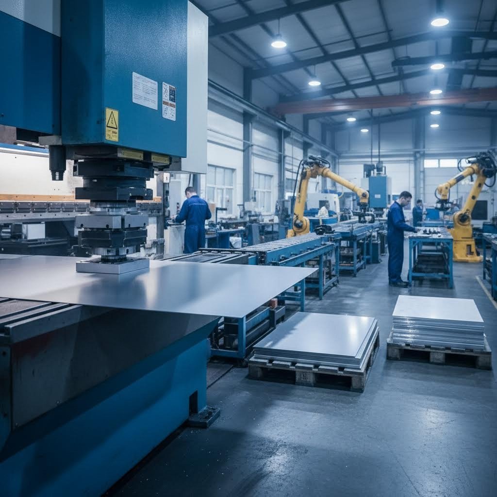
Ever wondered how a flat piece of metal transforms into the sleek laptop casing on your desk or the structural components inside an aircraft? That's aluminium sheet fabrication at work—a manufacturing process that shapes flat aluminum sheets into functional parts through a series of controlled operations.
At its core, aluminium fabrication involves taking thin, flat sheets of aluminum and converting them into precise components using cutting, bending, forming, and joining techniques. Unlike casting or forging, which start with molten metal or heated billets, sheet fabrication works exclusively with pre-formed flat material, typically ranging from 0.5mm to 6mm in thickness.
What Sets Aluminium Sheet Fabrication Apart from Other Metalworking
When you compare aluminum fab to other metalworking processes, the differences become clear. CNC machining removes material from solid blocks, often wasting 60-80% of the original stock. Die casting requires expensive molds and works only with molten metal. Sheet fabrication, however, reshapes existing material with minimal waste—making it both cost-effective and environmentally friendlier.
One of the most important facts about aluminum is its exceptional strength-to-weight ratio. Aluminum weighs roughly one-third as much as steel while offering impressive structural capabilities. This characteristic makes it the preferred metal for fabrication in industries where every gram matters—from aerospace to electric vehicles.
Additionally, aluminum naturally forms a protective oxide layer that resists corrosion without requiring additional coatings. This inherent property, combined with its excellent formability, explains why manufacturers increasingly choose this material over alternatives like steel or stainless steel.
The Core Processes That Define Sheet Metal Transformation
Understanding what happens during fabrication helps you avoid costly project mistakes. The process typically follows a logical sequence, though specific projects may require variations:
- Cutting – Laser, waterjet, or plasma methods slice sheets to size and create patterns with precision tolerances as tight as ±0.1mm
- Bending – Press brakes fold the material along straight axes to create angles, channels, and enclosures
- Stamping – Dies press shapes into the sheet, enabling mass production of consistent components
- Welding – TIG or MIG techniques join separate pieces into unified assemblies
- Finishing – Anodizing, powder coating, or other treatments enhance appearance and durability
Each operation builds upon the previous one. A design flaw in the cutting stage cascades through every subsequent process—which is precisely why understanding these fundamentals prevents expensive rework later.
From the aluminum things surrounding you daily—smartphone frames, kitchen appliances, architectural panels—to mission-critical aerospace components, this fabrication method enables modern manufacturing at scale. The key to success lies not in the equipment alone but in understanding how material properties, process parameters, and design decisions interact throughout the entire workflow.
Choosing the Right Aluminum Alloy for Your Fabrication Project
Here's where many fabrication projects go wrong before they even begin—choosing the wrong alloy. You might have a perfect CAD design and access to top-tier equipment, but selecting 7075 when you need extensive bending will guarantee cracked parts and wasted material. Let's break down exactly which aluminum alloy sheets work best for specific fabrication requirements.
Matching Alloy Properties to Your Fabrication Requirements
Think of aluminum alloys like tools in a toolbox—each serves a specific purpose. The four-digit numbering system tells you the primary alloying element, while temper designations (like H32 or T6) indicate how the material was processed to achieve its final properties.
Before diving into specifics, ask yourself these questions:
- Will the part require significant bending or forming?
- Does the application involve welding multiple pieces together?
- Will the component face marine or corrosive environments?
- Is maximum strength more critical than workability?
- What's your budget, and how quickly do you need material?
Your answers will point you toward the right alloy family. Here's how the most common aluminum alloy sheet metal options compare across critical fabrication characteristics:
| Alloy Grade | Formability Rating | Weldability | Corrosion Resistance | Typical Applications | Best Fabrication Methods |
|---|---|---|---|---|---|
| 3003-H14 | Excellent | Excellent | Good | General sheet work, cooking utensils, roofing | Bending, spinning, deep drawing |
| 5052-H32 | Excellent | Excellent | Excellent (saltwater) | Marine components, fuel tanks, enclosures | Bending, welding, forming |
| 6061-T6 | Good | Excellent | Good | Structural frames, machinery, automotive | Machining, welding, laser cutting |
| 7075-T6 | Low | Poor (prone to cracking) | Excellent | Aerospace, military, high-stress components | Machining, laser cutting only |
Notice how the relationship between strength and workability follows a predictable pattern? As you move from 3003 to 7075, strength increases while formability decreases. This tradeoff is fundamental to alloy selection—there's no single "best" choice, only the best choice for your specific application.
Why 5052 Dominates Sheet Metal Applications
If you're wondering "is 5052 aluminum bendable?"—the answer is a resounding yes. Alum 5052 H32 has earned its reputation as the workhorse of aluminum sheet fabrication for good reason. The addition of magnesium and chromium to the base aluminum creates a material that bends without cracking, welds without complications, and resists corrosion even in harsh marine environments.
The H32 temper designation indicates the material has been strain-hardened and then stabilized—giving it enough ductility for cold working operations while maintaining consistent mechanical properties. This makes 5052 aluminum sheet metal the default recommendation for projects requiring:
- Multiple bend operations or complex formed shapes
- Welded assemblies using TIG or MIG techniques
- Outdoor installations or marine grade aluminum 5052 applications
- Budget-conscious projects without sacrificing quality
Marine applications particularly benefit from 5052 aluminium because it contains no copper—a key factor in saltwater corrosion resistance. Boat hulls, dock fittings, fuel tanks, and coastal architectural panels almost universally specify this alloy.
When 6061's Strength Matters More
Don't dismiss 6061-T6 just because it's less forgiving in bending operations. This alloy offers approximately 32% higher ultimate tensile strength compared to 5052, making it essential for structural applications where load-bearing capacity trumps formability concerns.
The T6 temper indicates the material underwent solution heat treatment followed by artificial aging—a process that maximizes both tensile and fatigue strength. Choose 6061 when your project involves:
- Structural frames and load-bearing components
- Parts that will be primarily machined rather than bent
- Applications requiring heat treatment after fabrication
- Components where the superior strength-to-weight ratio justifies the extra care needed during forming
One critical note on weldability: while both 5052 and 6061 weld excellently, 6061 requires larger internal bend radii and specialized tooling for cold forming. Many fabrication shops simply don't bend 6061 because the risk of cracking outweighs the benefits. If your design requires both bending and high strength, consider fabricating bent sections from 5052 and welding them to machined 6061 structural elements.
The 7075 Exception—Maximum Strength, Minimum Flexibility
When strength requirements approach steel or titanium territory, 7075-T6 enters the conversation. With tensile strength roughly 1.5 times greater than 6061, this zinc-magnesium-copper alloy appears in aerospace structures, high-performance sporting equipment, and military applications where weight savings justify premium pricing.
However, 7075 comes with significant fabrication limitations. The material's hardness makes it nearly impossible to bend at standard sheet metal radii without cracking. Perhaps more critically, 7075 is not really weldable—the metal tends to crack after welding, limiting its use to individual machined components rather than welded assemblies.
Reserve 7075 for applications where parts will be laser cut and machined to final dimensions, with no bending or welding required. If your project demands both high strength and weldability, reconsider your design approach or explore titanium alloys instead.
Understanding these alloy characteristics prevents the costly mistake of discovering material limitations mid-project. But selecting the right alloy is only half the equation—choosing the correct gauge thickness determines whether your design will actually perform under real-world conditions.
Understanding Gauge Thickness and When Each Matters
You've selected the perfect alloy for your project—now comes the next critical decision that trips up even experienced fabricators. How thick should your aluminum sheet be? Get this wrong, and you'll either waste money on unnecessarily heavy material or end up with parts that buckle under load.
Here's what makes gauge sheet metal confusing: the numbering system runs backward from what you'd expect, and aluminum gauges don't match steel gauges at all. A 10-gauge aluminum sheet measures 2.588mm thick, while 10-gauge stainless steel comes in at 3.571mm. Order based on the wrong gauge chart, and you'll receive material that's completely wrong for your application.
Decoding Aluminum Gauge Numbers for Project Planning
The gauge system dates back to the 1800s when manufacturers measured sheet metal thickness aluminum by weight rather than direct measurement. Lower gauge numbers indicate thicker material—think of it as counting the number of times wire was drawn through dies to make it thinner. The more drawing operations, the higher the gauge number and the thinner the result.
For aluminum specifically, the standard gauge scale provides these conversions. If you've ever wondered how many mm is a 6 gauge, this reference table answers that question along with other common specifications:
| Gauge (GA) | Thickness (inches) | Thickness (mm) | Typical Applications | Forming Considerations |
|---|---|---|---|---|
| 6 | 0.1620 | 4.115 | Heavy structural plates, industrial flooring | Requires high-tonnage press brakes; limited bend angles |
| 8 | 0.1285 | 3.264 | Structural frames, heavy-duty brackets | Industrial equipment needed; wide bend radii required |
| 10 | 0.1019 | 2.588 | Structural components, chassis parts | Standard shop equipment; 10ga aluminum thickness ideal for load-bearing |
| 12 | 0.0808 | 2.052 | Heavy enclosures, automotive panels | Good balance of rigidity and formability |
| 14 | 0.0641 | 1.628 | Equipment housings, architectural panels | Versatile; forms easily on most press brakes |
| 16 | 0.0508 | 1.290 | HVAC ductwork, general enclosures | Easy forming; watch for springback |
| 18 | 0.0403 | 1.024 | Light enclosures, signage, trim | Forms readily; may require stiffening features |
| 20 | 0.0320 | 0.813 | Thin aluminum sheet metal applications, reflectors | Prone to distortion; handle carefully |
| 22 | 0.0253 | 0.643 | Roofing, kitchen equipment, flashing | Flexible; supports sharp bends |
| 24 | 0.0201 | 0.511 | Decorative panels, packaging | Very flexible; limited structural use |
Notice that anything thicker than approximately 6mm (around 4 gauge) transitions from "sheet" to "plate" classification. Most sheet metal fabrication works within the 0.5mm to 6mm range, with thinner gauges requiring specialized handling to prevent distortion.
Thickness Selection Based on Structural Requirements
Choosing between thin sheet aluminium and heavier gauges comes down to answering one fundamental question: what forces will your finished part experience? A decorative panel faces completely different demands than a structural bracket supporting equipment weight.
For enclosure applications, consider these guidelines:
- Electronics enclosures (minimal handling): 18-20 gauge provides adequate protection while minimizing weight and cost
- Industrial equipment housings (regular access): 14-16 gauge resists denting and maintains appearance over time
- Outdoor electrical cabinets: 12-14 gauge handles environmental exposure and occasional impact
- Heavy machinery guards: 10-12 gauge withstands industrial environments and protects against debris
Structural components demand a different calculation entirely. When parts carry loads or resist forces, the thickness directly affects deflection and ultimate strength:
- Mounting brackets and supports: 10-12 gauge minimum; thicker for dynamic loads
- Chassis and frame components: 8-10 gauge for vehicles and equipment; analyze specific load cases
- Platforms and flooring: 6-8 gauge with diamond tread patterns for slip resistance
- Structural beams and channels: Often 1/4 inch (6.35mm) or thicker—1 4 aluminum sheet metal transitions into plate territory
Remember that formed features like bends, flanges, and ribs dramatically increase stiffness without adding material. A well-designed 16-gauge enclosure with strategic brake bends can outperform a flat 12-gauge panel while using less material and costing less to produce.
Getting gauge selection right saves both money and headaches—but thickness is just one variable in successful fabrication. The cutting, bending, and forming operations that transform flat sheets into finished parts each introduce their own challenges and parameters worth understanding.
Core Fabrication Processes from Cutting to Forming
You've selected the right alloy and specified the correct gauge—now comes the part where projects actually succeed or fail. The fabrication floor is where theoretical decisions meet practical reality, and understanding each process parameter means the difference between parts that perform and scrap metal heading to the recycling bin.
When you fabricate sheet metal, the sequence matters as much as the individual operations. Each step builds upon the previous one, and mistakes compound quickly. Here's the logical progression from flat sheet to finished component:
- Nesting and material preparation – Optimizing cut patterns to minimize waste and planning grain direction
- Cutting operations – Laser, waterjet, or mechanical methods to create blanks and features
- Deburring and edge preparation – Removing sharp edges and preparing surfaces for bending
- Forming and bending – Creating three-dimensional shapes from flat blanks
- Joining operations – Welding, fastening, or bonding separate components
- Finishing – Surface treatments, coating, and final inspection
Let's examine the critical parameters for each major operation that directly impacts your project's success.
Cutting Techniques That Preserve Material Integrity
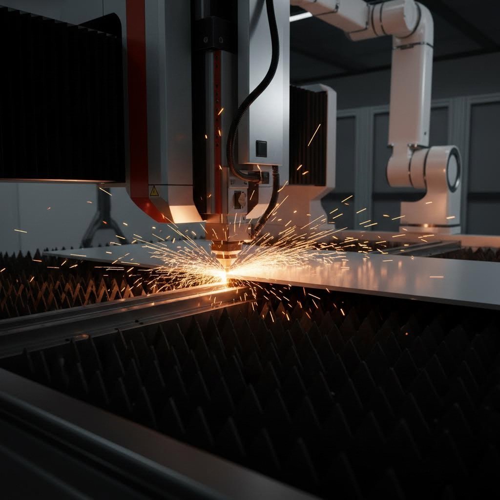
The cutting method you choose affects everything downstream—edge quality, heat-affected zones, and dimensional accuracy all influence how well subsequent bending and welding operations perform. For fabricating sheet metal, three primary cutting technologies dominate modern shops.
Laser cutting delivers the fastest results for aluminum sheets under 10mm thick. According to Xometry's comparison data, laser cutters operate at 20-70 inches per minute with cutting precision down to 0.15mm. That speed advantage makes laser the default choice for high-volume production. However, aluminum's reflective surface can cause problems with older CO2 laser systems—fiber lasers handle this material far more reliably.
Watch for these laser cutting parameters when working with aluminum:
- Assist gas: Use nitrogen for oxide-free edges that weld cleanly; oxygen leaves oxidized edges requiring preparation
- Power settings: Reduce power by 10-15% compared to steel settings to prevent excessive melting
- Speed adjustment: Aluminum's thermal conductivity requires faster traverse speeds to avoid heat buildup
- Focus position: Set focus slightly above the material surface for cleaner cuts on reflective alloys
Waterjet cutting eliminates heat concerns entirely—a critical advantage when you need to fabricate aluminum parts that can't tolerate any thermal distortion. The tradeoff? Speed drops dramatically to 1-20 inches per minute, and precision loosens to approximately 0.5mm. Waterjet excels at cutting thick material up to 250-300mm that would challenge any laser system.
Choose waterjet when your project involves:
- Heat-sensitive alloys like 7075-T6 where thermal stress causes cracking
- Thick plate material exceeding laser capacity
- Parts requiring no heat-affected zone whatsoever
- Mixed-material cutting in a single setup
Mechanical shearing remains the most economical option for straight cuts on thinner gauges. While it lacks the geometric flexibility of laser or waterjet, nothing beats a hydraulic shear for high-volume blanking operations. The key limitation? Edge quality degrades on thicker material, and you're limited to straight-line cuts only.
Bending Parameters for Clean Folds Without Cracking
This is where aluminum forming gets technical—and where most project failures originate. Bending seems straightforward until you discover that your carefully cut blanks crack at the bend line or spring back to an unusable angle.
The bend radius is your first critical parameter. According to Machinery's Handbook guidelines, aluminum typically requires a minimum inside bend radius of 1.0-2.0 times the material thickness, depending on alloy and temper. Push beyond these limits and the outer fibers of the bend stretch past their breaking point.
For custom aluminum bending operations, use these alloy-specific minimum bend radii:
| Alloy | Temper | Minimum Bend Radius (× thickness) | Notes |
|---|---|---|---|
| 3003 | H14 | 1.0t | Very forgiving; excellent for tight bends |
| 5052 | H32 | 1.5t | Standard recommendation for most applications |
| 6061 | T6 | 2.5-3.0t | Requires care; consider annealing for tight radii |
| 7075 | T6 | 4.0t or more | Often too brittle for bending; machine instead |
Springback compensation presents the second major challenge. When you release forming pressure, aluminum wants to partially return to its original flat state. This elastic recovery means your 90-degree bend might end up at 87 or 88 degrees unless you compensate.
The physics behind springback involves competing forces within the bent material. As Dahlstrom Roll Form explains, when metal bends, the inner region compresses while the outer region stretches. This density difference creates residual stresses that cause the material to spring back toward its original shape after forming pressure releases.
Experienced fabricators compensate through overforming—bending slightly past the target angle so springback lands you at the correct final dimension. For aluminum alloys:
- Soft tempers (O, H12): Overbend by 2-4 degrees
- Work-hardened tempers (H32, H34): Overbend by 4-6 degrees
- Heat-treated tempers (T4, T6): Overbend by 6-10 degrees; test samples recommended
Minimum flange length determines whether your press brake tooling can grip the material securely during forming. The general rule specifies flanges of at least 4 times the material thickness plus the bend radius. Shorter flanges slip during bending, creating inconsistent angles and damaged parts.
Understanding Bypass Notches and Their Purpose
Here's a detail that separates experienced fabricators from beginners: bypass notches in sheet metal forming serve a specific structural purpose that many designers overlook.
When two bends intersect at a corner, the material has nowhere to go. Without relief, the metal bunches up, creating distortion, cracking, or complete forming failure. Bypass notches—small cutouts at bend intersections—provide that essential relief by removing material that would otherwise interfere.
The bypass notches sheet metal forming purpose extends beyond simple material relief:
- They prevent material pileup that causes tooling damage
- They eliminate stress concentrations at corner intersections
- They allow sequential bending operations without interference
- They improve dimensional accuracy on enclosed box shapes
Size your notches at minimum 1.5 times material thickness in width, and extend them slightly beyond the bend intersection point. Too small and you'll still experience interference; too large and you create unnecessary gaps in your finished part.
Mastering these cutting and bending fundamentals prevents the most common fabrication failures. But even perfect process parameters can't compensate for material issues or environmental factors—challenges that require their own troubleshooting strategies before they derail your project.
Troubleshooting Fabrication Challenges Before They Happen
So you've selected the right alloy, calculated your bend radii, and programmed your press brake with springback compensation. Everything should go smoothly, right? Not quite. Aluminum's unique material properties create challenges that catch even experienced fabricators off guard—and understanding these issues before they wreck your project saves both time and money.
Here's the paradox: the same aluminum flexibility that makes this material so formable also makes it unpredictable under certain conditions. When aluminum is malleable, it bends beautifully under controlled pressure. But that same malleability means the material responds dramatically to heat input during welding, creating distortion patterns that steel fabricators rarely encounter.
Let's examine the most common fabrication failures and the proactive strategies that prevent them.
Preventing Common Bending Failures in Aluminum Sheet
Cracking at the bend line remains the number one failure mode in 5052 aluminum bending and other alloy forming operations. When you see fractures appearing along the outer radius of your bend, several factors might be responsible—and identifying the root cause determines whether your solution actually works.
Watch for these warning signs and their corresponding solutions:
- Orange peel texture on bend surface – Material grain is running parallel to the bend line. Rotate your blank 90 degrees so the grain runs perpendicular to the bend axis
- Hairline cracks on the outer radius – Bend radius is too tight for the alloy and temper. Increase radius to at least 1.5× material thickness for 5052, or 2.5× for 6061-T6
- Complete fracture at bend apex – Material may be work-hardened from previous operations. Consider annealing before forming, or switch to a softer temper
- Inconsistent bend angles across a batch – Springback varies between sheets. Verify all material comes from the same heat lot and confirm consistent temper designation
- Edge cracking extending into the bend – Rough edges from cutting operations create stress concentrations. Deburr all edges before bending, especially laser-cut parts
The aluminum malleable characteristic that enables complex forming also creates another challenge: work hardening. Each time you bend, stamp, or form aluminum, the crystalline structure deforms and becomes progressively harder. Attempt too many forming operations on the same part, and the once-ductile material becomes brittle enough to crack.
For complex parts requiring multiple bends, plan your forming sequence carefully. Start with the most critical bends while the material remains most formable, and save minor adjustments for last. If your design demands extensive forming, consider intermediate annealing treatments to restore ductility between operations.
Managing Heat Distortion During Welding Operations
Welding 5052 and other aluminum alloys presents a fundamentally different challenge than bending. While forming failures happen instantly, welding distortion develops progressively as thermal stresses accumulate—and by the time you notice the problem, significant correction work may be required.
According to ESAB's technical guidance, aluminum's thermal conductivity is approximately five times greater than low-carbon steel, while its coefficient of thermal expansion is nearly double. This combination means heat spreads rapidly through the workpiece while causing proportionally larger dimensional changes—a recipe for warping that requires deliberate countermeasures.
The malleable aluminium properties that facilitate bending work against you during welding. As the weld pool cools and shrinks, the soft surrounding material offers little resistance to the contraction forces. The result? Parts that twist, bow, or pull completely out of alignment.
Implement these strategies to control heat distortion:
- Minimize weld volume – Overwelding is the most common cause of excessive distortion. Use fillet weld gauges to ensure you're depositing only the required amount of material
- Balance welds around the neutral axis – Placing similar-sized welds on opposite sides of a structure allows shrinkage forces to counteract each other
- Use backstep welding sequences – Weld short sections in the opposite direction of overall progression, allowing each deposit to lock previous sections in place
- Preset components for expected movement – If you know a weld will pull a joint closed by 3 degrees, start with the joint preset 3 degrees open
- Employ rigid fixturing – Clamps and jigs resist movement during welding; back-to-back assembly of matching parts provides mutual restraint
Alloy selection also affects welding outcomes. As Action Stainless notes, 6061 aluminum is particularly prone to cracking in the heat-affected zone when cooled too quickly. Preheating thicker sections to 150-200°F helps reduce thermal shock, while using the appropriate 4043 or 5356 filler metal prevents hot cracking in susceptible alloys.
Surface Preparation Requirements Before Finishing
Fabrication challenges don't end when forming and welding are complete. The surface condition of your aluminum parts directly determines whether finishing processes succeed or fail—and aluminum's rapid oxidation creates a narrow window for proper preparation.
Within hours of exposure to air, aluminum develops a thin oxide layer that melts at over 3,700°F—far higher than the base metal's melting point. During welding, this oxide layer interferes with puddle formation and weld quality. Before finishing, it blocks adhesion of paints, powder coatings, and anodizing treatments.
Proper surface preparation follows a two-step approach:
- Solvent cleaning – Remove oils, greases, and handling residues using acetone, isopropyl alcohol, or commercial aluminum cleaners. These contaminants will burn into the surface during any thermal process
- Mechanical oxide removal – Use stainless steel brushes (never carbon steel, which contaminates aluminum), non-woven abrasive pads, or chemical etching to remove the oxide layer immediately before the next process
The critical word here is "immediately." Clean aluminum begins re-oxidizing within minutes of preparation. For welding, complete your joint within four hours of cleaning. For finishing processes, coordinate cleaning with your coating application schedule to minimize re-oxidation time.
Understanding these fabrication challenges transforms potential project failures into manageable process parameters. But prevention only works when you have clear quality standards to measure against—specifications that define what "acceptable" actually means for your specific application.
Quality Standards and Design Tolerances for Precision Results
You've mastered alloy selection, calculated bend parameters, and implemented distortion prevention strategies. But here's where many projects still fall apart: without defined quality standards and measurable tolerances, you can't distinguish acceptable parts from scrap. Performance aluminum fabrication demands specifications that everyone—designers, fabricators, and inspectors—can agree upon before production begins.
The gap between "close enough" and "within tolerance" often determines whether your fabricated parts assemble correctly, function as designed, and survive their intended service life. Let's bridge the gap between general fabrication knowledge and the specific tolerance values that define production-ready aluminum components.
Design Tolerances That Ensure Fabrication Success
Every fabrication operation introduces dimensional variation. The question isn't whether your parts will deviate from nominal dimensions—they will. The question is how much deviation your application can tolerate while still functioning correctly.
When working with aluminum fabrication services, these tolerance ranges represent industry-standard capabilities for common operations:
| Fabrication Operation | Standard Tolerance | Precision Tolerance | Notes |
|---|---|---|---|
| Laser cutting | ±0.127mm (±0.005") | ±0.076mm (±0.003") | Fiber lasers achieve tighter tolerances on aluminum |
| Waterjet cutting | ±0.254mm (±0.010") | ±0.127mm (±0.005") | Varies with material thickness and cutting speed |
| Press brake bending | ±0.5° angular | ±0.25° angular | CNC brakes with backgauges achieve precision tolerances |
| Formed dimensions | ±0.381mm (±0.015") | ±0.254mm (±0.010") | Cumulative tolerance across multiple bends |
| Hole location | ±0.127mm (±0.005") | ±0.076mm (±0.003") | From true position; tighter for mating assemblies |
| Material thickness | Per gauge chart | Per gauge chart | Reference 5052 aluminum gauge chart for specific values |
According to Protocase's tolerance specifications, 5052-H32 aluminum thickness tolerances range from ±0.08mm for 20-gauge material up to ±0.35mm for 0.250" plate. These incoming material variations must be factored into your overall tolerance stackup—you can't hold tighter finished dimensions than your raw material allows.
Beyond individual operation tolerances, successful designs account for feature-to-feature relationships that affect assembly and function:
- Hole-to-edge distance: Maintain minimum 2× material thickness to prevent edge tear-out during punching or drilling
- Hole-to-bend distance: Keep holes at least 3× material thickness plus bend radius away from bend lines to prevent distortion
- Minimum flange length: As Approved Sheet Metal's formula specifies—4× material thickness plus bend radius ensures reliable forming
- Notch-to-bend clearance: Notches should extend beyond the bend intersection by at least 1× material thickness
Inspection Criteria for Production-Ready Parts
Tolerances only matter if you can verify them. A skilled aluminium fabricator implements inspection protocols that catch deviations before parts ship—not after they fail in assembly or service.
When evaluating aluminum fabrication services providers or establishing your own quality program, expect these inspection capabilities:
- First article inspection (FAI): Complete dimensional verification of initial production parts against drawings before full production begins
- In-process checks: Statistical sampling during production runs to catch drift before it creates bulk scrap
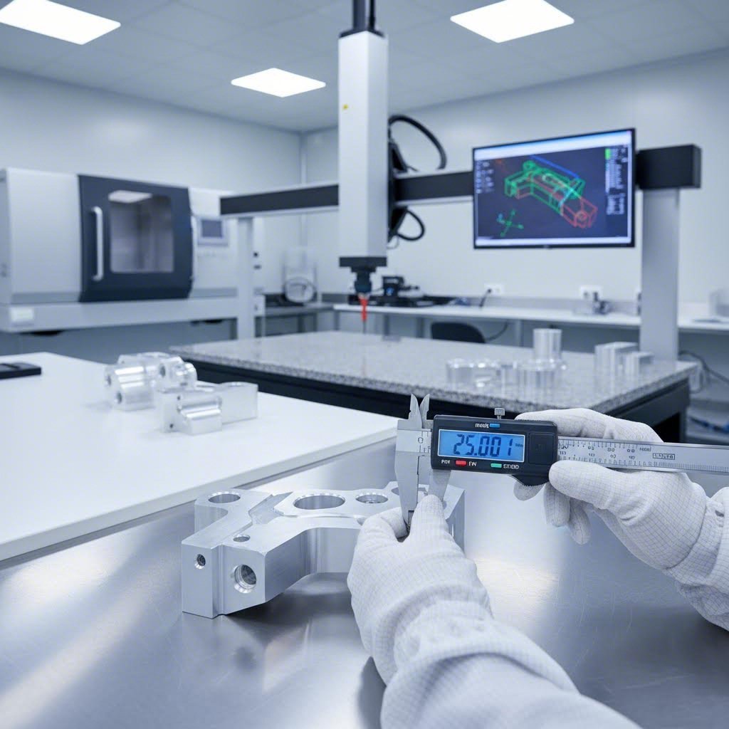
- CMM verification: Coordinate measuring machine inspection for critical dimensions and complex geometries
- Visual inspection criteria: Documented standards for surface finish, weld quality, and cosmetic requirements
- Material certification: Mill test reports confirming alloy chemistry and mechanical properties
Industry certifications provide external validation of quality systems. According to Tempco Manufacturing's quality documentation, certifications like ISO 9001:2015 require organizations to define effective quality management systems while identifying continuous improvement areas. For aerospace applications, AS9100D certification adds additional requirements specific to flight-critical components.
What should certified aluminum suppliers for custom products provide? At minimum, expect:
- Material certifications tracing alloy and temper to original mill source
- Inspection reports documenting measured dimensions versus tolerances
- Process documentation showing fabrication parameters used
- Nonconformance procedures for handling out-of-tolerance conditions
- Traceability systems linking finished parts to raw material lots
Precision standards vary significantly by industry application. Electronics enclosures might accept ±0.5mm dimensional tolerances, while aerospace structural components demand ±0.1mm or tighter. Medical device housings require documented inspection protocols under ISO 13485, while automotive stamping parts often follow IATF 16949 quality standards.
The key takeaway? Define your tolerance requirements before requesting quotes from any aluminum fabricator. Tighter tolerances require more precise equipment, slower processing, and additional inspection—all of which affect cost and lead time. Match your specifications to actual functional requirements rather than defaulting to unnecessarily tight tolerances that inflate project costs without adding value.
With quality standards established and inspection criteria defined, your fabricated parts can move confidently toward the finishing processes that determine their final appearance and long-term durability.
Surface Preparation and Finishing for Lasting Performance
Your fabrication work is flawless—precise cuts, clean bends, and solid welds. Then the powder coating peels off within six months, or the anodized finish develops unsightly blotches. What went wrong? In nearly every case, the answer traces back to surface preparation. The aluminum sheet material leaving your fabrication station might look ready for finishing, but invisible contaminants and oxide layers determine whether that finish lasts years or weeks.
Here's the reality: aluminum begins forming a thin oxide layer the moment it contacts air. While this natural oxidation provides some corrosion protection, it creates adhesion problems for applied finishes. Understanding how to clean aluminum oxidation and prepare surfaces properly separates professional-quality results from premature coating failures.
Surface Preparation Steps That Determine Finish Quality
Think of surface preparation as building a foundation. No matter how expensive your coating system, it can only perform as well as the surface beneath it allows. For thin aluminum sheeting and thicker plates alike, preparation follows a consistent sequence that removes contaminants layer by layer.
Start with solvent degreasing to eliminate oils, lubricants, and handling residues that accumulated during fabrication. According to Empire Abrasives' fabrication guide, acetone or alkaline detergent solutions work effectively for this initial cleaning. Avoid alcohol-based cleaners—they can react with aluminum and leave problematic residues.
Next comes the critical step of cleaning aluminum oxide from the surface. The naturally-forming oxide layer creates a barrier that prevents coatings from bonding directly to the base metal. You have several options for oxide removal:
- Mechanical abrasion – Non-woven pads or stainless steel brushes physically remove the oxide layer while creating surface texture that improves coating adhesion
- Chemical etching – Acid-based solutions dissolve the oxide layer uniformly; chromate conversion coatings like Alodine simultaneously remove oxide and deposit a corrosion-resistant film
- Abrasive blasting – Aluminum oxide or glass bead media create consistent surface profiles for coating adhesion on larger parts
Timing matters critically here. Once you've removed the oxide layer, the clock starts ticking. Fresh aluminum begins re-oxidizing immediately—you typically have four hours or less before the new oxide layer becomes thick enough to compromise coating adhesion. Coordinate your cleaning schedule with your finishing process to minimize this window.
Finishing Options from Anodizing to Powder Coating
With properly prepared surfaces, you can choose from several finishing systems—each offering distinct advantages for specific applications. The right choice depends on your environmental exposure, aesthetic requirements, and functional demands.
- Anodizing – This electrochemical process converts the aluminum surface into a hard, integral oxide layer 5-25 micrometers thick. According to Protolabs' comparison data, anodized finishes become part of the metal itself—they won't peel or flake because there's no separate coating layer to fail. Type II sulfuric acid anodizing provides good corrosion resistance, while Type III hard anodizing creates wear-resistant surfaces approaching the hardness of some steels. Best for: precision components requiring tight tolerances, heat exposure, and maximum durability
- Powder coating – Electrostatically applied powder particles fuse into a 50-150 micrometer thick continuous film during heat curing. The thicker coating excels at impact resistance and provides excellent UV stability with outdoor-rated formulations. Powder coating offers virtually unlimited color matching to RAL standards. Best for: architectural panels, outdoor equipment, and applications demanding specific color matching
- Chromate conversion coating – Brands like Alodine and Iridite apply quickly (1-5 minutes) and create thin protective films that accept paint excellently. These coatings provide moderate corrosion protection while maintaining electrical conductivity. Best for: electrical enclosures, components requiring subsequent painting, and aerospace applications
- Paint systems – Liquid primers and topcoats offer flexibility for field application and repair. Modern two-component epoxy and polyurethane systems provide excellent protection when applied over properly prepared or conversion-coated surfaces. Best for: large structures, repair situations, and custom color requirements
Your end-use environment should drive finishing decisions. Marine applications demand anodizing or marine-grade paint systems. Architectural installations benefit from anodized or powder-coated finishes with proven UV resistance. Industrial equipment often uses powder coating for its impact resistance and repairability—damaged areas can be touched up, though color matching isn't always perfect.
Remember this key principle: surface preparation determines finish longevity more than the coating system itself. A premium powder coating over contaminated aluminum fails faster than a basic finish over properly prepared metal. Invest your attention in the preparation steps, and your finishing choices will deliver their full performance potential.
With finishing processes understood, the final consideration becomes equally practical—how do the costs of materials, complexity, and finishing choices combine to affect your total project budget?
Cost Factors and Smart Sourcing for Fabrication Projects
You've designed your part, selected the right alloy, and specified appropriate tolerances. Now comes the question that determines whether your project actually moves forward: what will this cost? Understanding the factors that drive aluminium fabrication services pricing helps you make informed decisions—and avoid expensive surprises when quotes arrive.
Here's what many project managers miss: by the time you're requesting fabrication quotes, roughly 80% of your manufacturing costs are already locked in. According to Fictiv's DFM guide, design choices made early in development determine everything downstream—from material selection to process complexity. This means cost optimization starts at the design stage, not the purchasing stage.
Cost Drivers That Impact Your Fabrication Budget
When aluminum sheet producers and custom aluminum fabricators calculate project pricing, they're evaluating several interconnected factors. Understanding these drivers helps you anticipate costs and identify opportunities for savings.
Material costs form your baseline. According to Komacut's cost guide, aluminum's higher per-kilogram cost compared to mild steel makes it less attractive for pure material cost comparisons. However, aluminum's lightweight nature often reduces shipping costs and can simplify handling during fabrication—factors that offset some of the material premium.
Consider these material-related cost factors:
- Alloy selection – Common alloys like 5052 and 3003 cost less than specialty grades like 7075; availability affects lead times and pricing
- Thickness variations – Standard gauge thicknesses ship faster and cost less than special-order dimensions
- Sheet size optimization – Parts nested efficiently on standard sheet sizes waste less material than awkward geometries
- Minimum order quantities – Material suppliers often require minimum purchases; small projects may pay premiums
Complexity factors multiply your base costs quickly. Each additional operation—whether an extra bend, a welded assembly, or tight tolerance requirements—adds setup time, processing time, and inspection requirements. A simple bracket with two bends might cost $15 per piece, while a similar-sized enclosure with eight bends, hardware inserts, and welded corners could reach $85.
Design complexity impacts costs through:
- Number of fabrication operations – Each cut, bend, punch, or weld adds processing time
- Tolerance requirements – Tighter tolerances demand slower processing speeds and more inspection
- Secondary operations – Hardware insertion, tapping, countersinking, and deburring add labor content
- Weld complexity – Simple seam welds cost less than intricate multi-pass structural welds
Volume considerations create significant per-piece cost variations. Fabricating aluminum in quantities of 10 versus 1,000 changes the economics dramatically. Setup costs—programming CNC equipment, configuring press brake tooling, creating fixtures—get amortized across your total quantity. Higher volumes also justify process optimization that wouldn't make sense for prototype quantities.
Balancing Quality Requirements with Project Economics
Smart sourcing means matching your requirements precisely to what you actually need—not over-specifying tolerances or finishes that drive up costs without adding functional value.
Design for Manufacturing (DFM) analysis early in your project identifies cost reduction opportunities before they become locked into your design. As manufacturing experts note, DFM practices eliminate many issues that typically arise in production, including extended development cycles and unnecessary costs. Comprehensive DFM support from your fabrication partner can identify problematic features like overly tight tolerances, unnecessarily complex geometries, or material choices that complicate processing.
Consider these cost optimization strategies when finalizing your design:
- Specify the widest acceptable tolerances – Apply tight tolerances only where function demands them; loosen non-critical dimensions
- Standardize bend radii – Using consistent inside radii across your design reduces tooling changes
- Design for standard tooling – Common punch sizes and brake dies process faster than custom tooling
- Minimize weld content – Formed features often provide adequate strength at lower cost than welded assemblies
- Consolidate finishing requirements – Batch similar parts for the same finish treatment to optimize setup costs
Finishing expenses often surprise project planners. Anodizing, powder coating, and chromate conversion each add $3-15 per square foot depending on specification requirements. Complex masking for selective finishing multiplies these costs further. Factor finishing into your initial budget rather than treating it as an afterthought.
Evaluating Fabrication Services Providers
Not every aluminum fabricator offers the same capabilities, quality systems, or service levels. According to Howard Precision Metals' supplier guide, partnering with suppliers who lack appropriate capabilities can negatively impact production, profits, and business relationships.
When evaluating aluminium fabrication services providers for aluminum fabricated products, investigate these factors:
- Quality certifications – ISO 9001 provides baseline quality management; industry-specific certifications like IATF 16949 for automotive applications ensure your parts meet stringent requirements for chassis, suspension, and structural components
- Prototyping capabilities – Rapid prototyping services (some providers offer 5-day turnarounds) let you validate designs before committing to production tooling
- Quote responsiveness – Fast quote turnaround (12-hour response times from leading suppliers) indicates operational efficiency and customer focus
- DFM support availability – Providers offering comprehensive DFM analysis help optimize your designs for cost-effective production
- Production scalability – Verify the fabricator can scale from prototype quantities through automated mass production as your needs grow
For automotive aluminum parts manufacturing, IATF 16949 certification deserves particular attention. This automotive-specific quality standard requires documented processes, statistical process control, and continuous improvement systems that ensure consistent quality across production runs. When your aluminum sheet fabrication supplies mission-critical automotive components, this certification provides assurance that your parts will meet demanding industry requirements.
The sourcing decision ultimately balances cost, quality, and capability. The lowest quote rarely delivers the best value if it comes with quality problems, missed deliveries, or limited technical support. Invest time evaluating potential fabrication partners before production begins—the right partnership prevents costly problems that far exceed any savings from aggressive pricing negotiations.
With cost factors understood and sourcing strategies established, the final piece of the puzzle involves understanding how different industries apply these fabrication principles to their specific applications and requirements.
Real-World Applications and Your Next Steps
Everything we've covered—alloy selection, gauge specifications, bending parameters, quality standards, and cost factors—comes together when aluminum sheet metal fabrication meets actual industry requirements. The theoretical knowledge matters, but seeing how different sectors apply these principles reveals why specific choices work for specific applications.
Think about it this way: the things that are made out of aluminum surrounding you right now—your laptop enclosure, the aircraft overhead compartment, the EV battery housing—each required fabricators to make deliberate decisions about materials, processes, and finishes. Understanding these industry-specific requirements helps you apply the right approach to your own projects.
Industry Applications Where Aluminium Sheet Excels
Different industries prioritize different material properties. Aerospace engineers obsess over weight savings. Automotive manufacturers balance strength against crash performance. Electronics designers worry about EMI shielding and heat dissipation. Here's how aluminum fabrications serve each sector's unique demands:
- Automotive components – Chassis panels, heat shields, and structural brackets demand 5052 or 6061 alloys in 10-14 gauge thicknesses. Precision assemblies for suspension and structural components require IATF 16949-certified manufacturing partners who understand automotive quality requirements. Fabricated aluminum parts must survive vibration, temperature cycling, and corrosion exposure over vehicle lifetimes exceeding 150,000 miles
- Aerospace structures – Weight-critical applications favor 7075-T6 for maximum strength-to-weight ratio, though its poor formability limits fabrication to laser cutting and machining rather than bending. Wing skins, fuselage panels, and interior components use sheet metal aluminium extensively, with chromate conversion coatings providing corrosion protection while maintaining electrical conductivity for lightning strike dissipation
- Electronics enclosures – EMI shielding requirements drive material selection toward conductive aluminum alloys with consistent electrical properties. Enclosures typically use 16-20 gauge 5052 for formability, with tight tolerances on mating surfaces to ensure proper grounding. Anodized finishes provide both cosmetic appeal and additional surface hardness
- Architectural panels – Building facades and interior cladding prioritize appearance and weather resistance. Thinner gauges (18-22) reduce weight on building structures, while anodized or PVDF-coated finishes deliver decades of UV resistance. Consistent color matching across large production runs requires careful supplier qualification
- Marine equipment – Saltwater exposure demands marine-grade 5052 aluminum for its superior corrosion resistance. Boat hulls, deck fittings, and fuel tanks benefit from 5052's excellent weldability, allowing fabricators to create watertight assemblies without the cracking risks associated with higher-strength alloys
- Medical device housings – Cleanability and biocompatibility requirements often specify anodized finishes that resist chemical cleaning agents. Precision tolerances ensure proper sealing for IP-rated enclosures, while material traceability requirements demand documented supply chains from certified aluminum suppliers
Matching Fabrication Approaches to End-Use Requirements
Successful aluminum metal fabrication connects material selection to process selection to finishing—each decision supporting the next. Consider how this flow works for a typical automotive heat shield application:
- Material selection – 5052-H32 aluminum provides the formability needed for complex shield geometries while offering adequate temperature resistance for underbody applications
- Cutting method – Laser cutting delivers the precision required for mounting hole locations and edge profiles, with nitrogen assist gas ensuring clean edges for subsequent bending
- Forming approach – Progressive die stamping creates embossed patterns that increase stiffness without adding thickness, while press brake operations form mounting flanges
- Finishing choice – Heat-resistant coatings or bare aluminum with chromate conversion protect against corrosion while surviving exhaust system temperatures
Compare this to an electronics enclosure project, where the fabrication flow prioritizes different outcomes:
- Material selection – 5052-H32 at 18 gauge balances EMI shielding effectiveness against weight and cost constraints
- Cutting method – Laser cutting with tight tolerances on mating edges ensures consistent contact for electrical grounding across enclosure seams
- Forming approach – CNC press brake bending with backgauge precision creates square corners essential for proper lid fitment and EMI seal performance
- Finishing choice – Chromate conversion coating maintains electrical conductivity for grounding while powder coat over conversion coating provides durability and aesthetic appeal
Your Next Steps for Project Success
You now have the knowledge to avoid the fabrication mistakes that kill projects. Before launching your next aluminium sheet fabrication project, work through this action checklist:
- Define functional requirements first – What loads, environments, and service conditions will your parts experience? These requirements drive every subsequent decision
- Select alloy and temper based on fabrication needs – Match your bending, welding, and finishing requirements to alloy capabilities using the comparison tables provided earlier
- Specify tolerances that reflect actual function – Apply tight tolerances only where assembly or performance demands them; loosen non-critical dimensions to reduce costs
- Plan your fabrication sequence – Consider how cutting, bending, and joining operations interact; design features that support rather than complicate each process step
- Coordinate surface preparation with finishing – Clean surfaces within the appropriate time window before coating operations; specify preparation methods that match your chosen finish
- Evaluate fabrication partners carefully – Verify capabilities, certifications, and DFM support availability before committing to production
For automotive applications specifically, partnering with manufacturers who offer comprehensive DFM support can identify design optimizations that reduce costs while improving manufacturability. Rapid prototyping capabilities—some suppliers deliver prototypes in as few as five days—let you validate designs before committing to production tooling. When your aluminum sheet fabrication supplies chassis, suspension, or structural components, IATF 16949 certification from your fabrication partner ensures the quality systems necessary for automotive-grade production.
The difference between successful fabrication projects and costly failures often comes down to decisions made before fabrication even begins. Armed with the knowledge from this guide, you're positioned to make those decisions confidently—selecting the right materials, specifying appropriate processes, and partnering with capable fabricators who can transform your designs into production-ready aluminum components.
Frequently Asked Questions About Aluminium Sheet Fabrication
1. Is aluminium fabrication expensive?
While aluminium's initial material cost exceeds mild steel, the total project cost often balances out due to aluminium's lightweight nature reducing shipping costs, easier formability reducing processing time, and natural corrosion resistance eliminating coating requirements in many applications. Long-term savings come from aluminium's durability and low maintenance needs. To optimize costs, leverage DFM support from IATF 16949-certified manufacturers who can identify design improvements that reduce fabrication complexity while maintaining quality.
2. Is aluminum easy to fabricate?
Yes, aluminium is known for excellent formability compared to other metals, making it easier to cut, bend, and weld into desired shapes. Alloys like 5052-H32 offer exceptional workability for sheet metal operations. However, success depends on selecting the right alloy for your specific process—7075 is nearly impossible to bend without cracking, while 3003 handles tight radii beautifully. Understanding springback compensation and proper bend radii for each alloy prevents common fabrication failures.
3. What is the best aluminum alloy for sheet metal fabrication?
5052-H32 dominates sheet metal fabrication as the most versatile choice, offering excellent formability, superior weldability, and outstanding corrosion resistance—especially in marine environments. It bends without cracking, welds without complications, and costs less than specialty alloys. For structural applications requiring higher strength, 6061-T6 provides approximately 32% greater tensile strength but demands larger bend radii and more careful handling during forming operations.
4. How do I prevent cracking when bending aluminum sheet?
Cracking prevention starts with proper bend radius selection—maintain at least 1.5 times material thickness for 5052 and 2.5 times for 6061-T6. Orient blanks so the material grain runs perpendicular to the bend line, not parallel. Deburr all edges before bending since rough edges create stress concentrations. For complex parts requiring multiple bends, plan your forming sequence to perform critical bends first while material remains most ductile.
5. What certifications should I look for in an aluminum fabrication supplier?
ISO 9001 provides baseline quality management assurance, while industry-specific certifications indicate specialized capabilities. For automotive aluminium sheet fabrication supplying chassis, suspension, or structural components, IATF 16949 certification ensures documented processes, statistical process control, and continuous improvement systems. Aerospace applications require AS9100D certification. Also verify rapid prototyping capabilities, DFM support availability, and material traceability systems that link finished parts to original mill sources.