 Small batches, high standards. Our rapid prototyping service makes validation faster and easier —

What Is Orbital Welding? How It Cuts Defects And Guesswork
What Is Orbital Welding in Plain English?
What Orbital Welding Means
Orbital welding is a mechanized welding method in which the arc or welding tool travels in a full orbit around a fixed tube, pipe, or fitting to produce a uniform weld.
That is the short answer to what is orbital welding. In simple terms, it replaces much of the hand motion and judgment of a manual welder with a controlled machine movement. The name comes from that circular path, or orbit, around the joint.
In real-world use, orbital welding is most closely tied to precision tube and pipe work. It is commonly used for tube-to-tube, pipe-to-pipe, and tube-to-tubesheet joints where repeatability, leak tightness, and clean weld surfaces matter. A quick historical note helps explain why the process exists. TWI traces its development to aerospace work in 1960, where it was created to reduce TIG operator error and improve uniform tube welds.
How It Differs From Manual Welding
With hand welding, the welder must guide the torch around the entire joint while dealing with changing body position, visibility, gravity, and heat. That gets harder on overhead sections or in cramped spaces. Even a skilled welder can see results vary slightly from one joint to the next.
Orbital welding changes that. The workpiece is typically held still while a weld head guides the arc around it in a controlled path. Because the settings can be programmed and reused, orbital tube welding is valued for consistent results on repeated joints. That is the first technical layer beginners should know: the process is not just automatic movement, but repeatable movement under controlled parameters.
Where Orbital Welding Is Commonly Used
You are most likely to encounter orbital welding in industries and environments such as:
- Semiconductor and clean-room piping systems
- Pharmaceutical and biotechnology process lines
- Food and beverage tubing
- Aerospace fluid systems
- Chemical, petrochemical, oil and gas, and power applications
- Jobs with tight access, poor visibility, or harsh conditions
That broad use comes down to one idea: the same joint needs the same weld, every time. The details behind that consistency live in the automated cycle itself, where arc control, shielding gas, and travel around the joint start to matter.
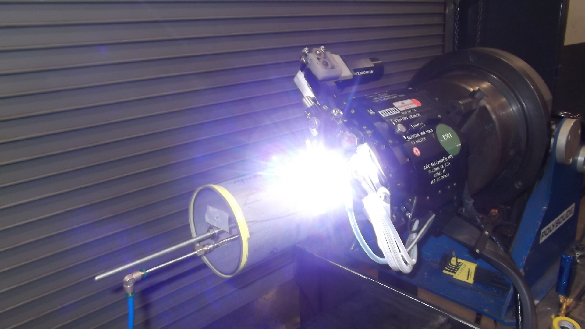
How the Orbital Welding Process Works
That circular motion sounds simple, but the real value comes from how tightly the system controls the weld while it travels around the joint. In practice, the orbital welding process is usually a mix of mechanized movement and a very clean arc process.
Why Orbital Welding Is Often TIG Based
Orbital welding describes the method of movement, not always a completely separate welding science. In many tube and pipe applications, the arc process underneath it is GTAW, also called TIG. The Fabricator explains that automatic orbital GTAW creates an arc between a nonconsumable tungsten electrode and the base material, while shielding gas protects the electrode, weld puddle, and solidifying metal from atmospheric contamination.
That is why orbital tig welding is so common when cleanliness, leak integrity, and repeatable appearance matter. TIG gives the process a stable, precise arc. The orbital system adds controlled motion and programmed variables. In shop talk, you may hear people call it a tig orbital setup. The meaning is straightforward: TIG provides the arc, and automation provides consistency.
How the Weld Head Moves Around the Joint
On most precision tube jobs, the tube stays fixed and the weld head clamps around it. Inside that head, the electrode travels in a full orbit around the joint. The same source notes that the rotor and electrode are housed in the weld head, which rotates around the tube. Some applications differ by size, access, or joint design, but for common tube welding, the usual arrangement is a stationary workpiece with a moving torch path.
This matters more than it first appears. Manual welding changes as the welder shifts body position, hand angle, and viewing direction. A gtaw orbital welding system reduces that variation by repeating the same path around the entire 360-degree joint.
What Happens During an Automated Weld Cycle
A typical automated cycle is easier to understand in simple stages:
- The operator selects or loads a weld program suited to the joint and material.
- The weld head is positioned around the tube, and shielding gas is delivered through the head to protect the weld area.
- The system starts the arc between the tungsten electrode and the base metal.
- The head rotates in a controlled orbit while the controller manages travel speed, arc gap, current control, and gas flow.
- The system can step from one preset condition to another at programmed points around the joint or at predetermined times.
- After the full circumference is completed, the arc stops and the weld solidifies under protected conditions.
Consistency comes from holding critical variables at preset levels while keeping the weld protected from contamination.
The technical reason repeatability improves is simple: fewer important variables are left to moment-by-moment hand judgment. That is why two welds made with the same program can look far more alike than two manual welds on the same tube. And once you start asking how the machine keeps all of that under control, the power supply, controller, weld head, and gas hardware become the real story.
Orbital Welding Equipment and What Each Part Does
Consistency sounds like software, but hardware is what turns a saved weld schedule into a real joint. An orbital welding machine is really a coordinated package of power, control, motion, gas delivery, and fit-up tools. That is why orbital welding machines are usually judged less by one headline feature and more by how well the whole package works together on the shop floor.
What the Power Supply and Controller Do
The power supply is the electrical engine. SEC Industrial describes it as the unit that converts incoming electrical current into controlled output for the arc, with programmable settings for variables such as current, voltage, and pulse. The controller sits above that power source and manages the sequence of the weld. It stores programs, links the power source to the weld head, and helps the operator repeat the same setup on the next joint. The Fabricator notes that newer systems can also store weld data for retrieval and reporting, which matters when traceability is part of quality control.
For a buyer, the practical question is not just how advanced the screen looks. It is whether the controller can reliably recall the right procedure for the right material, diameter, and wall thickness without inviting easy mistakes.
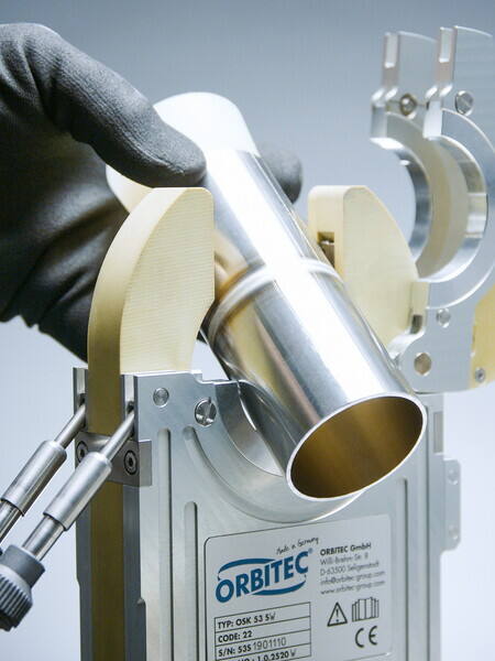
How the Orbital Weld Head Guides the Arc
The orbital welding head is where programmed control becomes physical motion. It holds the tungsten electrode and guides it around the joint in a controlled orbit while the tube or pipe usually stays fixed. That repeatable path is a big reason an orbital welding system can reduce bead variation from one weld to the next.
Head selection matters more than many first-time users expect. The chosen orbital welding head has to match the size range, available clearance, and application style. Morgan Industrial points out that size changes often require the correct collets or cassettes, because a head that is slightly off-center can turn a good program into an uneven weld. Some heads also rely on cooling features to manage heat during longer or heavier-duty work, another role highlighted by SEC Industrial.
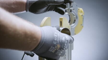
Why Gas Control and Fit Up Hardware Matter
Gas and alignment hardware rarely get the spotlight, but they directly affect cleanliness and weld stability. Shielding gas flows through the head to protect the tungsten, weld puddle, and solidifying metal. Inside the tube, purge devices help remove oxygen before the weld starts. Morgan Industrial warns that poor purging can lead to sugaring on the backside of the weld, a serious problem in sanitary and high-purity service. Fit-up hardware matters just as much. Fixtures, clamps, and alignment tools hold the parts still and keep the joint centered under the electrode. Some newer power supplies even automate gas control and help prevent weld starts without gas flow.
| Component | Practical job | Operator concern | Common setup mistake |
|---|---|---|---|
| Power supply | Creates stable arc power and applies programmed output | Enough control for the material and wall thickness being welded | Using a generic setting instead of a qualified program |
| Controller or HMI | Stores programs, runs the weld sequence, and may record data | Easy program recall, clear inputs, and traceability | Loading the wrong procedure for the tube size or material |
| Weld head | Holds the tungsten and guides the arc around the joint | Fit to application, access clearance, and size range | Choosing a head that does not center well on the workpiece |
| Collets, cassettes, clamps, fixtures | Align and hold the tube or pipe so the joint stays centered | Repeatable fit-up and fast, correct changeover | Loose clamping or wrong size hardware |
| Shielding gas delivery | Protects the tungsten, puddle, and hot weld metal | Confirmed gas flow and clean gas path | Starting the cycle with poor flow or leaks |
| Purge setup | Removes oxygen from inside the tube before welding | Good sealing and even gas distribution | Rushing purge preparation or using poorly sealed plugs |
| Cooling and monitoring features | Manage heat, protect components, and support diagnostics | Duty cycle, alarms, and review of stored weld data | Ignoring warnings or treating data logging as optional |
Seen up close, orbital welding equipment is less like one smart box and more like a chain. Clean power, accurate motion, stable gas flow, and precise alignment all have to hold at the same time. If one link is weak, the machine repeats that weakness with impressive consistency, which is why joint preparation and setup discipline matter so much before the arc ever starts.
Tube Orbital Welding From Prep to Inspection
Machines are only as consistent as the setup behind them. In tube orbital welding, small prep mistakes tend to show up later as oxidation, uneven bead shape, or failed inspection. Whether you are working with a compact orbital tube welding machine or a larger orbital pipe welding machine, the workflow stays remarkably similar: prepare the joint, align it accurately, control the purge, verify the program, then weld and inspect.
Preparing the Joint Before Welding Starts
A good weld usually begins long before the arc. Morgan Industrial notes that clean, square cuts and proper end preparation are critical because burrs, deformation, or contamination can create defects later in the cycle.
| Pre-weld check | What to confirm | Why it matters |
|---|---|---|
| Cut quality | Tube or pipe is cut square to length | Helps the ends meet evenly |
| Edge condition | Burrs removed, faced, or beveled if required | Improves fit-up and arc consistency |
| Surface cleanliness | No oil, grease, debris, or fingerprints | Reduces porosity and inclusions |
| Consumables | Correct tungsten, collets, and head hardware installed | Keeps the arc centered and repeatable |
| Gas and cables | Connections secure and undamaged | Prevents leaks and unstable operation |
- Cut the material accurately. Orbital saws and cutters are often used because they help produce a clean, consistent cut without distorting thin-wall tube.
- Face or bevel as needed. Facing removes burrs and imperfections. Heavier-wall joints that use filler may also need bevel preparation.
- Clean the weld area carefully. Morgan recommends gloves and a clean, lint-free cloth with alcohol to remove oils and debris, especially on stainless and sanitary work.
- Check the tungsten and head setup. The electrode, collets, or cassettes have to match the application so the arc starts in the right place.
Setting Fit Up Purge and Program Controls
Preparation only pays off when the joint is centered and the inside of the tube is protected. In both sanitary tube work and heavier orbital pipe welding, poor fit-up can turn a solid weld schedule into a bad weld.
- Align the joint under the electrode. Clamp the parts so the ends stay flush and stable. Morgan highlights alignment tools and tacking clamps for sanitary applications because consistent fit-up leads to consistent welds.
- Set the internal purge. Purge plugs or similar devices seal the ends and distribute gas through the inside diameter. This helps remove oxygen and reduce backside sugaring.
- Load or build the weld program. Many controllers use the weld head model, material, outside diameter, and wall thickness to generate a starting schedule. Morgan also notes that the cycle is often divided into multiple levels so heat can change as the part warms.
- Run checks before the real weld. Red-D-Arc stresses checking gas connections for leaks, confirming equipment condition, and making a test weld on matching material instead of trusting saved settings from a previous job.
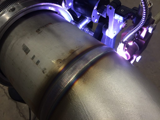
Running the Weld and Checking the Result
Once the joint is clean, centered, and fully purged, the automated cycle can do its job with far less guesswork than hand welding.
- Start the weld cycle. Morgan describes a typical sequence as pre-purge, arc start, a short travel delay to establish the puddle, controlled rotation with programmed pulse or level changes, tie-in overlap, downslope, and post-purge cooling gas.
- Let the weld cool under protection. Do not rush to handle the joint while it is still hot and vulnerable to discoloration or disturbance.
- Inspect the finished weld. Check bead uniformity, color, tie-in, and overall appearance. If the application allows internal review, look for purge-related oxidation or concavity on the inside surface as well.
The order is what makes an orbital system reliable. A polished controller cannot compensate for dirty tube ends, weak alignment, or rushed purging. What separates a merely completed weld from a truly repeatable one lives inside the setup variables themselves, especially diameter, wall thickness, gas quality, and program control.
Orbital Welding Systems Variables That Control Quality
The program only works when it matches the joint in front of it. In orbital welding systems, weld quality comes from balancing several variables at once, not from chasing one magic amperage number. An automatic tube welding machine can repeat a bad setup just as faithfully as a good one, which is why stable inputs matter so much.
How Diameter and Wall Thickness Affect Setup
Tube diameter and wall thickness set the basic thermal load of the weld. Thin wall tube heats quickly, so it usually needs lower overall heat input or faster travel to avoid excessive penetration and distortion. Thicker wall material absorbs more heat and often needs slower travel, more current, or a different pulse strategy to reach full fusion.
Diameter changes the length of the orbit, which affects surface travel speed around the joint. That is why experienced operators think in terms of heat input over the full circumference, not just motor rotation. Useful starting examples appear in the JTM Group guide: for stainless tube, average current is often estimated at about 1 amp per 0.001 inch of wall thickness, and weld speed may start around 4 to 10 inches per minute, with 5 inches per minute offered as a practical baseline. Those are starting points, not universal settings.
Why Shielding Gas and Purge Conditions Matter
Gas quality protects the weld from contamination on both sides of the joint. JTM notes that argon is the most common shielding gas for the outside diameter and the most common purge gas for the inside diameter. If shielding is weak, the weld can discolor, lose corrosion resistance, or develop porosity. If flow is poorly controlled, too little gas leaves the puddle exposed and too much can create turbulence.
Internal purge condition is just as important as external shielding, especially on stainless and sanitary tube. In ultra-clean work, NODHA notes that high-purity argon, such as 99.999 percent, is commonly used to limit oxidation. Automated orbital welding does not change that rule. A beautiful outside bead can still hide root oxidation if purge sealing, gas purity, or purge time is poor.
Which Program Variables Most Influence Consistency
Current, travel speed, arc length, pulse strategy, tungsten condition, and joint consistency all work together. Change one and the others often need to move with it. For example, faster travel usually demands enough current to maintain fusion, while a longer arc can widen the bead and reduce control.
JTM explains that orbital programs commonly use multiple current levels because the tube heats up as the weld progresses. A practical starting method is to use at least four levels, with the last level set lower than the first, often around 80 percent of level 1. The same source also gives pulse examples, including a 3:1 peak-to-background current ratio and a 35 percent pulse width as starting points for development. Even an automatic orbital welding machine still depends on test coupons, clean tungsten, and repeatable fit-up before those values become a reliable procedure.
| Variable | Why it matters | What changes it influences | What can go wrong if it is neglected |
|---|---|---|---|
| Tube diameter | Changes orbit length and surface speed around the joint | Travel speed logic, heat distribution, bead uniformity | Uneven penetration or poor tie-in around the circumference |
| Wall thickness | Determines how much heat the joint can absorb | Current demand, travel speed, pulse need | Lack of fusion on thicker walls or burn-through on thin walls |
| Travel speed | Controls how long heat stays in one area | Penetration, bead width, distortion risk | Too fast can undercut or miss fusion, too slow can overheat the joint |
| Current control | Provides the energy that creates penetration | Fusion depth, puddle size, overall heat input | Weak welds, excessive penetration, or unstable bead shape |
| Arc length | Affects arc focus and stability | Bead width, penetration, arc consistency | Arc wander, inconsistent fusion, erratic appearance |
| Shielding gas quality and flow | Protects the electrode and weld pool from contamination | Surface color, porosity risk, corrosion resistance | Oxidation, discoloration, porosity, unstable arc behavior |
| Internal purge condition | Protects the root side of the weld | Root cleanliness, internal oxidation, sanitary performance | Sugaring, root discoloration, reduced corrosion resistance |
| Tungsten condition | Shapes arc start and arc focus | Arc stability, penetration consistency, repeatability | Arc wandering, poor starts, inconsistent bead profile |
| Joint consistency | Keeps the programmed arc relationship constant | Fit-up repeatability, bead symmetry, penetration control | Mismatch, variable root profile, defect repeatability from joint to joint |
The pattern is hard to miss. Orbital welding becomes reliable when the joint, gas, electrode, and program all stay inside a tight window. That mix of precision and sensitivity is exactly why the process can outperform manual welding on repeat tube work, and why the tradeoffs deserve a clear look too.
Orbital Welding vs Manual Welding for Industrial Pipes
The same tight control that improves bead quality also changes the tradeoffs. In orbital welding vs manual welding for industrial pipes, the real question is not which method is universally better. It is which one fits the joint type, production volume, inspection burden, and working conditions. For repetitive tube and pipe joints, automatic orbital welding reduces much of the variation that comes from hand motion, fatigue, and changing body position. That advantage is real, but it comes with costs that are easy to underestimate.
Where Orbital Welding Delivers Clear Advantages
On repeatable circular joints, orbital systems earn their reputation. Axxair describes automated welding as a way to produce regular, repeatable welds while reducing defects, and Codinter highlights the same strengths in precision, cleanliness, and parameter control.
Pros
- Very high repeatability from one joint to the next
- Cleaner, more uniform welds when shielding and purge control are stable
- Higher productivity on long runs of similar joints once setup is complete
- Reduced operator-to-operator variation during the weld cycle
- Useful documentation and traceability in quality-sensitive work
- Strong fit for regulated, sanitary, and high-purity applications
That is why pipe orbital welding is common where leak integrity, surface cleanliness, and consistent results matter more than improvisation.
What Makes It More Demanding Than It Looks
The difficult part often happens before the arc starts. Codinter points to the high initial investment, specialized training, equipment complexity, and dependence on proper joint preparation. Rayoung also notes the need for stable power, controlled conditions, and careful alignment.
Cons
- Higher upfront equipment cost
- Longer setup time for clamping, purging, and program selection
- Greater sensitivity to fit-up and cleanliness mistakes
- Fixture and access demands can limit field practicality
- Not every weld geometry is a good match
When Manual Welding May Still Be Better
Manual welding still has a clear place. Small-batch fabrication, repair work, retrofit jobs, and awkward field positions often favor a skilled welder over an orbital pipe welder. If the work changes constantly, manual welding can be faster to deploy and easier to adapt on the spot. For repetitive pipe orbital welding, automation usually wins. For one-off joints with changing geometry, manual welding often remains the more practical tool.
| Aspect | Orbital welding | Manual welding |
|---|---|---|
| Repeatability | Very consistent when the same program and fit-up are used | Varies more with welder technique and conditions |
| Cleanliness | Strong control of arc path and shielding helps produce cleaner welds | Can be excellent, but results depend more on operator consistency |
| Productivity | Best on repeated joints after setup is complete | Best on short runs, repairs, and changing job conditions |
| Setup time | Higher upfront setup and preparation demand | Lower initial setup for many field tasks |
| Skill demands | Shifts skill toward setup, programming, and process control | Requires continuous torch control and strong hand skill |
| Flexibility | Most effective on circular, repeatable joints | More adaptable to varied geometry and access limits |
So the process is not magic. It is a disciplined system with clear strengths and equally clear boundaries. That matters on the inspection side too, because an automated cycle can repeat a setup mistake just as faithfully as a good weld.
Orbital Weld Inspection and Troubleshooting Guide
The strongest case for automation disappears fast if the finished joint is never checked properly. An orbital weld can look smooth on the outside and still have purge damage, lack of fusion, or arc-related inconsistency. That is why good shops inspect in a fixed order, then trace any defect back to preparation, gas protection, equipment condition, or program control.
How to Inspect an Orbital Weld in Sequence
A disciplined sequence helps separate real root causes from guesswork. The workflow outlined by Cumulus Quality is a useful model because it starts with visual examination, moves into dimensional review, checks process conditions, and ends with documentation.
- Set up the inspection. Use proper lighting, safety gear, drawings, and the applicable weld procedure.
- Examine the outside bead. Look for cracks, porosity, undercut, irregular reinforcement, poor tie-in, or an uneven profile.
- Review the root side when accessible. On tube and pipe work, inspect for discoloration, oxidation, or sugaring. Miller notes that backside oxygen exposure can cause sugaring on stainless welds.
- Confirm dimensions. Measure weld size and profile with the required tools, and verify the assembly still meets alignment and fit requirements.
- Compare the process record. Check the selected program, gas setup, and any data captured by the orbital welding power supply or controller against the approved procedure.
- Use additional examination if required. When the job or code calls for it, radiographic or ultrasonic testing can help assess penetration and internal defects.
- Document the result. Record observations, photos, joint ID, and any corrective action before releasing the part or starting another cycle.
Automation can repeat a mistake with perfect consistency, so preparation and inspection still carry the quality burden.
Common Defects and Their Likely Causes
In orbital welding, the same few errors show up again and again. Orbital highlights lack of fusion, weld pool instability, inconsistent weld quality, and equipment malfunctions. TIG-focused troubleshooting from Miller adds familiar causes such as poor gas coverage, dirty material, excessive heat input, and unstable arc length.
| Defect | Likely cause | Corrective action |
|---|---|---|
| Contamination or dirty bead | Oil, dirt, scale, or contaminated filler or base metal | Recut or reclean the joint, protect prepared parts, and verify shielding before welding again |
| Lack of fusion | Poor fit-up, excessive arc length, travel too fast, or insufficient heat input | Recheck alignment, reduce arc length, and confirm the program matches the material and wall thickness |
| Porosity | Gas leaks, disturbed shielding, or contamination in the joint | Inspect hoses and fittings, check gas delivery, and remove contaminants from the tube ends |
| Root oxidation or sugaring | Weak internal purge or oxygen on the backside of the weld | Improve purge sealing, allow full purge time, and confirm purge gas practice |
| Tungsten-related defects | Contaminated, worn, or poorly prepared tungsten | Regrind or replace the electrode and confirm correct positioning in the orbital weld head |
| Arc instability | Variable arc length, leaks, worn consumables, or control drift | Check electrode condition, gas integrity, and machine setup before making a test weld |
| Inconsistent bead appearance | Misalignment, variable gap, unstable travel, or calibration issues | Inspect clamps, centering, and maintenance status of the weld head and controller |
Simple Corrective Actions Before the Next Cycle
When a defect appears, resist the urge to change three settings at once. Start with the basics that most often drift in real production. Cleanliness comes first. Gas integrity comes next. Then check alignment, tungsten condition, and the loaded program. If the problem follows one machine instead of one joint, inspect the orbital weld head for positioning issues and verify maintenance or calibration on the controller and power source, a step reinforced by Orbital.
A practical reset routine looks like this: stop production, review the failed weld visually, inspect consumables, confirm purge and shielding paths, compare the actual program to the qualified one, and run a test weld on matching material before returning to live parts. That habit does more than reduce scrap. It also shows whether the troubleshooting load fits your shop, your team, and your quality system, which becomes a very practical question when deciding between owning orbital equipment and relying on a specialist partner.
Buy an Orbital Welder or Use a Welding Partner?
A passed weld inspection does not automatically mean ownership is the right business move. Many teams reach this point and start looking for an orbital welder for sale, but the smarter choice depends on workload, joint type, training capacity, and how much equipment responsibility you want to carry in-house.
When Buying an Orbital Welder Makes Sense
Morgan Industrial's cost-benefit analysis lays out the tradeoff clearly. Buying orbital equipment brings a significant upfront cost, plus maintenance, repair responsibility, and some risk of obsolescence as systems improve. Even so, ownership can be cost-effective when the equipment is used extensively and continuously.
In practical terms, an orbital welder machine makes the most sense when your shop handles repeat tube or pipe joints every week, needs tight control over scheduling, and can support setup discipline internally. If you are still asking what is an orbital welder from a buyer's perspective, think beyond the hardware. You are really buying a process capability that includes procedures, maintenance, spare parts, and operator skill. Formal orbital welding training is available for welders, supervisors, engineers, and QA or QC personnel, which is a good reminder that automation still depends on trained people.
When Outsourcing the Welding Work Is Smarter
Some companies do not need permanent ownership to get consistent results. Morgan's review also shows why non-ownership models appeal to many users: lower initial cash outlay, less maintenance burden, more flexibility, and easier access to newer equipment. That same logic supports using machine orbital pipe welding services when your orbital work is occasional, project based, or too varied to keep orbital welders busy full time.
Outsourcing is often the better fit when the real need is qualified output rather than equipment possession. It can also be the cleaner option if your team would otherwise need added staffing, service support, and more orbital welding training just to cover a limited number of jobs. Before committing to another orbital welder for sale listing, it helps to ask a simple question: will this system earn its place every month, or sit idle between short runs?
How Automotive Manufacturers Should Evaluate Partners
Automotive sourcing adds one more filter: geometry. Orbital welding is strongest on repeatable circular tube and pipe joints. Chassis parts and structural assemblies often involve shapes that are better suited to robotic welding than an orbital weld head. For buyers in that category, Shaoyi Metal Technology is a relevant example of a specialist partner. The company highlights advanced robotic welding lines, an IATF 16949 certified quality system, and custom welding for steel, aluminum, and other metals. That does not make it a replacement for every orbital application. It does make it worth evaluating when the job is automotive, high precision, and not a classic tube orbit.
| Option | Best fit | Main advantage | Main limitation | Best question to ask |
|---|---|---|---|---|
| Shaoyi Metal Technology | Automotive chassis and high-precision metal assemblies | Specialized robotic welding support with an automotive quality framework | Not a direct substitute for dedicated orbital tube or sanitary pipe welding when the joint truly requires orbital travel | Is the part geometry better suited to robotic welding than orbital welding? |
| In-house orbital equipment | Frequent, repeatable tube and pipe production | Maximum scheduling control and internal process ownership | Higher capital cost, maintenance responsibility, and training burden | Will utilization stay high enough to justify ownership? |
| Outsourced machine orbital pipe welding services | Periodic or specialized tube and pipe jobs | Avoids major equipment investment while still accessing process capability | Less day-to-day control over timing and resource availability | Do we need the result regularly enough to bring it inside? |
| Broader automated welding partners | Mixed-geometry parts and production assemblies | More flexibility to match the welding method to the part | The selected process may not be orbital at all | Are we buying a machine, or the most suitable process outcome? |
A short buyer checklist keeps the decision grounded:
- How repetitive are our tube or pipe welds each month?
- Do our joints actually favor orbital welding, or a different automated method?
- Can our team support programming, maintenance, and inspection internally?
- Will we need ongoing training and procedure development?
- Is capital better spent on equipment, or preserved for production and quality needs?
- Do we need ownership, rental flexibility, or a qualified outside partner?
The right answer is usually less about enthusiasm for automation and more about fit. Repetitive circular joints reward ownership. Irregular demand and mixed geometry often reward partnership.
Frequently Asked Questions About Orbital Welding
1. What is orbital welding mainly used for?
Orbital welding is mainly used for circular tube and pipe joints that need the same result over and over again. It is common in semiconductor lines, pharmaceutical systems, food and beverage tubing, aerospace fluid lines, and other pipe applications where cleanliness, leak integrity, and repeatability matter. The process is especially valuable when access is tight or when surface quality on both sides of the joint is important.
2. Is orbital welding the same as TIG welding?
Not exactly. Orbital welding describes the controlled movement of the weld around the joint, while TIG, or GTAW, is often the arc process used inside that automated setup. In many systems, a tungsten electrode creates the arc and the weld head carries it around a fixed tube, which is why people often refer to orbital TIG welding.
3. What equipment is needed for orbital welding?
A typical orbital welding setup includes a power supply, a controller, a weld head, clamping or alignment hardware, shielding gas delivery, and an internal purge arrangement when the root side must stay clean. Some systems also store weld programs and quality records for repeat jobs. In practice, buyers should pay as much attention to fit-up tools and gas control as they do to the machine itself, because poor preparation can ruin an otherwise good program.
4. What causes defects in an orbital weld?
Most orbital weld defects start with setup drift rather than with the automation concept itself. Common causes include dirty tube ends, poor fit-up, weak purge sealing, gas leaks, worn tungsten, incorrect program selection, and an off-center weld head. Those problems can show up as oxidation, porosity, lack of fusion, arc instability, or an inconsistent bead, which is why good shops inspect preparation steps before changing multiple settings.
5. Should a manufacturer buy an orbital welder or outsource the work?
Buying makes sense when a company runs repeat tube or pipe welds often enough to justify equipment cost, maintenance, procedure control, and orbital welding training. Outsourcing is often smarter for occasional work, limited staff, or jobs that do not keep the machine busy. In automotive manufacturing, the decision also depends on part geometry, because some chassis and structural parts are better suited to robotic welding than orbital welding. In those cases, a specialist partner such as Shaoyi Metal Technology may be a better fit for high-precision production.