 Small batches, high standards. Our rapid prototyping service makes validation faster and easier —

Transfer Die Stamping Process Decoded: From First Hit To Final Part

What Transfer Die Stamping Actually Means for Metal Forming
When you need to manufacture complex metal parts with deep draws, intricate geometries, or multi-axis forming, understanding the transfer die stamping process becomes essential. This method represents one of the most versatile approaches to precision metal forming, yet many engineers and buyers struggle to grasp what sets it apart from other stamping techniques.
Transfer die stamping is a metal forming process where discrete blanks are cut from sheet material and mechanically transferred between independent die stations, with each station performing specific forming operations until the final part is complete.
Sounds straightforward? The real value lies in understanding why this process exists and what it enables. Unlike methods where parts remain connected to a continuous strip, die transfer systems physically separate each workpiece before moving it through the forming sequence. This fundamental difference unlocks manufacturing capabilities that would otherwise be impossible.
How Transfer Die Stamping Differs From Strip-Fed Methods
Imagine feeding a long ribbon of sheet metal through a machine. In progressive die stamping, that ribbon stays intact as it moves through each station. You'd see parts at various stages of completion, all still attached to the same strip. Only at the final station does the finished part get cut free.
Transfer stamping takes a completely different approach. The first station cuts a blank from the workpiece, and then a mechanical transport system—not the strip itself—moves that individual piece to subsequent stations. As noted by Aranda Tooling, this process uses bending, flanging, punching, and other techniques based on the desired shape, with each station contributing to the final form.
This distinction matters for several practical reasons:
- Parts can be rotated or repositioned between stations for multi-directional forming
- Larger components that wouldn't fit on a continuous strip become manufacturable
- Deep-drawn shapes requiring extreme material movement become achievable
- Material yield often improves since blanks can be nested efficiently
The Core Principle Behind Station-to-Station Part Movement
What makes this example of stamping so effective for complex parts? The answer lies in freedom of movement. When a blank travels independently through transfer dies, it can undergo operations from multiple angles and orientations. Progressive methods limit forming actions to what's achievable while the part remains attached to the carrier strip.
Consider a deep-drawn automotive housing. The material needs to flow dramatically during forming, sometimes requiring the blank to be completely inverted between operations. Transfer stamping accommodates this because the mechanical fingers or walking beam systems can grip, rotate, and reposition parts with precision that strip-fed methods simply cannot match.
According to Kenmode, transfer die stamping proves particularly valuable when parts require tube-shaped or enclosed forms, shell production, or when the component is too large for progressive stamping. The process also excels at incorporating secondary features like chamfering, cut-outs, pierced holes, ribs, knurls, and threading directly into primary operations.
Understanding this foundational concept prepares you to evaluate whether transfer die stamping fits your specific manufacturing needs—a decision that impacts tooling investment, production speed, and ultimately, your per-part costs.
The Complete Transfer Die Stamping Process Explained Stage by Stage
Now that you understand what separates transfer die stamping from strip-fed methods, let's walk through exactly how this process unfolds. What happens from the moment raw material enters a transfer stamping press until a finished part exits? Understanding each stage helps you appreciate why this method achieves results that other pressing and stamping techniques cannot match.
From Blank Loading to Final Ejection
Picture a massive coil of sheet metal, sometimes weighing several tons, mounted on an uncoiler at the front of a die-stamping machine. This is where every part begins its journey. The process follows a precise sequence that transforms flat stock into complex three-dimensional components.
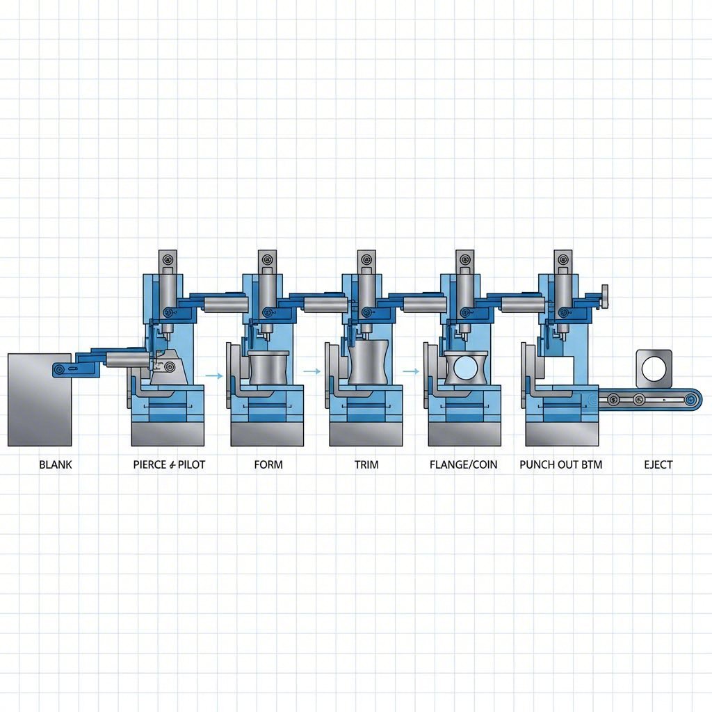
- Coil Feeding and Blank Creation: Raw material feeds from the coil into the first station, where a blanking die punches out the initial part shape. This cut severs all connection between the workpiece and parent material. Some operations use pre-cut blanks fed from a destacker instead, but the principle remains identical—individual pieces enter the system ready for independent handling.
- Transfer Mechanism Engagement: As the press ram rises and opens the die, part lifters raise the freshly cut blank off the lower die surface. Simultaneously, the mechanical transfer system activates. Two parallel rails running the length of the die move inward, and specialized fingers or grippers mounted on these rails clamp firmly onto the blank's edges.
- Precision Part Movement: With the blank secured, the entire transfer rail assembly executes a carefully choreographed motion: lifting vertically, moving horizontally to the next station, then lowering with extreme accuracy onto locating pins or nests in the receiving die. The fingers release, rails retract, and all this happens before the press ram begins its downward stroke. According to U-Need, this complete sequence occurs in a fraction of a second.
-
Sequential Forming Operations: The part progresses through multiple stations, each engineered to perform specific operations without overloading the material. Typical station operations include:
- Drawing: Creating cup-like shapes or deep cavities by forcing material into die cavities
- Redrawing: Further deepening or refining previously drawn features
- Piercing: Punching holes, slots, or openings in specific locations
- Forming: Creating bends, ribs, embossments, or contoured surfaces
- Trimming: Removing excess material and refining final part edges
- Secondary Operation Integration: Advanced transfer tooling can incorporate operations beyond basic forming. Tapping heads create threaded holes, welding units attach nuts or brackets, and automated systems insert plastic or rubber components—all within the same press cycle.
- Final Ejection: After the last station completes its operation, the transfer system grips the finished part one final time and deposits it onto a conveyor belt or directly into shipping containers. The component exits as a complete, often fully assembled part.
Why does this sequential approach work so effectively? Each station focuses on a limited set of operations, allowing dies to be optimized without compromise. The gradual forming progression prevents material from being overstressed, resulting in superior dimensional consistency and surface quality across production runs of millions of parts.
Understanding Transfer Mechanism Types and Their Functions
The heart of any transfer press stamping operation lies in its transfer mechanism—the system responsible for moving parts between stations with split-second timing and micron-level precision. Different mechanism types suit different applications, and understanding your options helps you specify the right equipment for your production needs.
Mechanical Finger Systems: The most common transfer mechanism uses paired rails equipped with cam-actuated fingers. These fingers open and close mechanically, synchronized to the press stroke through gears and linkages. The system's simplicity makes it reliable and cost-effective for standard applications. Fingers can be configured to grip part edges, internal features, or specialized tooling points depending on component geometry.
Walking Beam Systems: For larger parts or operations requiring extended travel distances, walking beam transfers provide robust solutions. These systems use a single beam or pair of beams that lift, advance, and lower in coordinated motion. Machine Concepts notes that walking beam configurations can be offered with servos located only at the beam ends, reducing complexity while maintaining precise control.
Servo-Driven Transfer Systems: Modern transfer stamping press installations increasingly utilize servo motors for transfer motion. These programmable systems offer significant advantages:
- Adjustable motion profiles optimized for specific part geometries
- Quick changeover between different jobs through stored programs
- Ability to synchronize with press signals, picking up parts before the transfer while the downstream press cycles—eliminating wait time and increasing throughput
- Generous adjustment range for different tooling heights, center-to-center dimensions, and part sizes
According to Machine Concepts, advanced servo-driven systems can operate in three modes: automatic cycling synchronized with press strokes, single-stroke on-demand operation, or full manual control. Job libraries storing up to 99 configurations enable rapid changeover for repeat production runs.
Part sensing adds another layer of sophistication to modern transfer tooling. End effector arms incorporate sensors verifying that each part has been captured and moved successfully. This prevents tooling damage from misfeeds and ensures every blank completes the full forming sequence. Whether your transfer system uses electromagnetic grippers with reverse polarity release for metal parts or vacuum systems with blow-off release for non-metallic components, reliable part detection remains essential for consistent production.
The mechanical principles behind transfer press stamping create a manufacturing environment where complexity becomes manageable. Each station performs focused operations, transfer mechanisms handle precision positioning, and the entire system operates as a coordinated unit—transforming raw blanks into finished components through a seamless progression of controlled forming steps.
When Part Geometry Requires Transfer Die Stamping
You've seen how the transfer die stamping process moves blanks through sequential stations with mechanical precision. But when does your part actually need this approach? The answer lies in geometry. Certain component features simply cannot be manufactured any other way, and understanding these requirements helps you specify the right process from the start.
Part Features That Demand Transfer Die Methods
Think about a metal stamping die attempting to form a deep cylindrical housing while the part remains attached to a carrier strip. The material would tear, buckle, or refuse to flow properly. Transfer die stamping solves this by allowing complete freedom of movement at each station. Here are the part characteristics that point directly toward this process:
- Deep-drawn components: Parts with height exceeding twice their minimum width qualify as deep draws. According to The Fabricator, some components may require as many as 15 or more drawing operations to achieve final depth—impossible while attached to a strip.
- Multi-directional forming requirements: When your design needs operations performed from different angles or requires the part to be rotated between stations, transfer systems deliver capabilities progressive methods cannot match.
- Complex 3D geometries: Enclosed forms, tube-shaped components, and shells with intricate surface features benefit from the repositioning flexibility inherent to transfer die operations.
- Multiple-surface operations: Parts requiring piercing, forming, or finishing on both top and bottom surfaces—or on sidewalls—need the manipulation only transfer mechanisms provide.
- Components too large for strip feeding: When blank dimensions exceed practical strip widths, transfer stamping becomes the logical choice. Larger automotive panels and appliance housings typically fall into this category.
What about draft angles and draw ratios? These design constraints directly impact manufacturability. Industry guidelines recommend designing flanges or die entry radii at approximately 6 to 8 times material thickness. This reduces forming severity and minimizes the number of draw operations required. However, if the die entry radius becomes too large, compressed metal can wrinkle before flowing into vertical walls—ultimately causing splits.
Severe draft angles combined with deep forms create particular challenges. When walls angle away from vertical in deep-drawn corners, the metal bridges between draw pad and punch, experiencing acute radial compression. Without proper constraint, significant wrinkling occurs. The electrical stamping process for motor laminations faces similar geometry considerations, though typically in thinner materials with different forming requirements.
Material Selection and Thickness Considerations
Choosing the right material affects both formability and final part performance. Not every alloy responds equally well to the demands of deep drawing and multi-stage transfer operations. Consider these factors when specifying materials for your transfer die stamping project:
Ductility and formability: As noted by Larson Tool's design guide, the lower the alloy content and temper, the more formable the material. Harder materials exhibit greater springback, requiring additional over-bend compensation in tooling design.
Material thickness impacts: Deep drawing fundamentally alters wall thickness throughout the forming process. The punch nose initially embosses material, creating a "shock line"—a pronounced thinning area around the bottom radius. Meanwhile, material at the blank's circumference gathers and can thicken by as much as 10% over original gauge. Metal stamping die design must accommodate this variation with appropriate clearances.
Which materials work best for transfer die applications?
- Low-carbon steel: Excellent formability, widely available in standard gauges, and cost-effective for high-volume production. Stock warehouse alloys often provide sufficient quality for most applications.
- Aluminum alloys: The aluminum stamping process requires careful attention to draw ratios since thin aluminum exhibits lower elongation than steel. Excessively large punch radii can create unacceptable drawing conditions where metal splits before proper flow occurs.
- Copper alloys: Good ductility makes these materials suitable for deep draws, though work hardening effects may require intermediate annealing between redraw operations.
- Stainless steel: Higher strength materials demand more forming force and exhibit pronounced springback. Flatness becomes more challenging to maintain as stamping forces distort edges.
According to Die-Matic's engineering guidelines, maintaining uniform wall thickness ensures even material flow and structural integrity during forming. Using proper corner radii and fillets reduces stress concentrations that lead to cracking. Managing draw depth-to-diameter ratios by staying within recommended limits—and utilizing multiple draw stages for deep parts—prevents the failures that occur when material is pushed beyond its forming limits.
Feature accessibility between stations deserves attention during design. Each transfer position must allow mechanical fingers to grip the part without interfering with formed features from previous operations. Tooling engineers evaluate these access points early in metal stamping die design, sometimes recommending geometry modifications that improve manufacturability without compromising function.
With geometry requirements and material considerations defined, you're positioned to evaluate how transfer die stamping compares against alternative methods for your specific application.
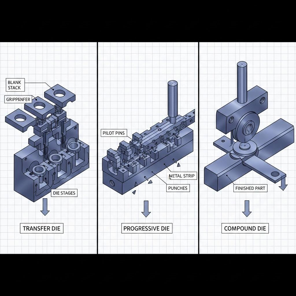
Transfer Die vs Progressive Die vs Compound Die Stamping
Now that you understand when part geometry demands transfer die methods, how does this process stack up against other stamping approaches? Choosing between transfer die, progressive die, and compound die stamping isn't just about capability—it's about matching the right method to your specific production requirements, budget constraints, and part complexity.
Many manufacturers struggle with this decision because existing comparisons focus on surface-level differences without providing actionable selection criteria. Let's fix that by evaluating all three methods against consistent benchmarks, then building a decision framework you can actually use.
Consistent Evaluation Criteria Across All Three Methods
Before diving into comparisons, you need to understand what each method fundamentally does. Progressive stamping keeps parts attached to a carrier strip as they move through stations—ideal for high-speed production of simpler geometries. Compound die stamping (sometimes called prog die in shorthand) performs multiple operations simultaneously in a single press stroke, creating flat parts with exceptional precision. Transfer die stamping, as you've learned, moves separated blanks between independent stations for complex three-dimensional forming.
According to Worthy Hardware's analysis, each method excels in different areas while presenting distinct limitations. Here's how they compare across critical evaluation criteria:
| Evaluation Criteria | Transfer Die Stamping | Progressive Die Stamping | Compound Die Stamping |
|---|---|---|---|
| Part Complexity Capability | Excellent—handles deep draws, multi-axis forming, enclosed shapes, and large components | Moderate—limited to parts manufacturable while attached to strip; simpler geometries preferred | Limited—best for flat, precision parts requiring simultaneous cutting operations |
| Production Speed | Moderate—transfer mechanisms require time between strokes | Highest—continuous strip feeding enables maximum throughput | Moderate to Low—single-stroke operation limits cycle time optimization |
| Ideal Production Volume | Medium to High—versatile for both short and long runs | High Volume—tooling investment favors runs exceeding 100,000+ parts | Low to Medium—precision focus suits smaller quantities |
| Tooling Investment | High—multiple independent stations require substantial die engineering | High—complex progressive dies with many stations demand significant investment | Moderate—simpler single-station tooling reduces upfront costs |
| Per-Part Cost at High Volume | Competitive—costs decrease significantly as volumes increase | Lowest—high-speed operation drives down per-part costs dramatically | Higher—slower cycles limit cost reduction potential |
| Setup Time | Longer—transfer mechanism synchronization and multi-station alignment required | Moderate—strip threading and station alignment needed | Shortest—single-station operation simplifies setup |
| Material Efficiency | Good—blanks can be nested efficiently from sheet stock | Variable—carrier strip creates inherent scrap between parts | Excellent—minimal scrap through optimized blank layouts |
| Flexibility for Design Changes | Moderate—individual stations can sometimes be modified independently | Limited—strip-based progression constrains modification options | Good—simpler tooling allows easier adjustment |
What does this comparison reveal? Progressive die & stamping operations dominate when you need maximum throughput for simpler parts. Compound dies and stamping excel at precision flat components where material efficiency matters. Transfer die stamping fills the gap where complexity exceeds what strip-fed methods can achieve.
Decision Framework for Stamping Method Selection
Comparisons alone don't answer the critical question: which method should you choose? Use this decision framework to work through your specific requirements systematically.
Start with part geometry. Ask yourself these questions:
- Does my part require deep drawing with height exceeding twice the minimum width?
- Are operations needed from multiple angles or on multiple surfaces?
- Does the component include enclosed forms, tube shapes, or complex 3D features?
- Is the blank size too large for practical strip feeding?
If you answered yes to any of these, progressive dies likely cannot manufacture your part. Transfer die stamping becomes your primary consideration.
Evaluate production volume requirements. According to industry analysis, the breakeven point between methods shifts based on annual quantities:
- Under 10,000 parts annually: Consider compound stamping die approaches or even single-operation tooling with manual handling—lower tooling investment may offset higher per-part costs.
- 10,000 to 100,000 parts annually: Transfer die stamping often hits the sweet spot, balancing tooling investment against per-part economics while handling complex geometries.
- Over 100,000 parts annually: If part geometry permits, progressive dies deliver the lowest per-part cost. For complex parts requiring transfer methods, volume justifies the tooling investment handily.
Consider secondary operation integration. What happens after stamping? If your part needs tapping, hardware insertion, or assembly operations, transfer die stamping can incorporate these within the press cycle—eliminating downstream handling and reducing total manufacturing cost. Progressive stamping offers limited integration options due to strip attachment constraints.
Address common misconceptions. Many engineers avoid transfer die stamping based on outdated assumptions:
- "Transfer dies are only for low-volume production." False—modern servo-driven transfer systems achieve stroke rates supporting high-volume manufacturing.
- "Setup times make transfer impractical." Misleading—stored job programs and quick-change tooling reduce changeover dramatically compared to legacy equipment.
- "Progressive dies always cost less per part." Depends on geometry—when parts require multiple secondary operations outside the die, transfer stamping's integrated approach often proves more economical.
The stamping die selection ultimately comes down to matching method capabilities with part requirements. Transfer die stamping isn't always the answer, but when your geometry demands it, no other approach delivers equivalent results. Understanding these distinctions positions you to specify the right process before tooling investment begins—saving both time and capital in your manufacturing program.
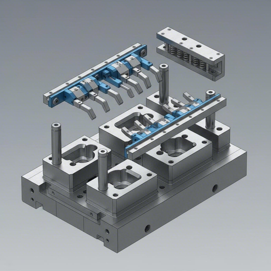
Tooling Design and Die Engineering Fundamentals
You've evaluated which stamping method fits your part requirements. Now comes the engineering challenge: how do you actually design transfer dies that deliver consistent results across millions of cycles? The answer lies in understanding the specific tooling considerations that separate successful transfer die stamping from costly trial-and-error approaches.
Unlike progressive stamping dies where the carrier strip provides inherent part control, transfer dies must account for completely independent workpiece handling at every station. This fundamental difference drives unique engineering requirements that experienced die designers address from the earliest concept stages.
Engineering Requirements for Transfer Die Design
What goes into designing a die stamping machine setup that performs reliably? According to The Fabricator, die designers need several critical pieces of information before beginning any transfer die project:
- Press specifications: Tonnage capacity, bed size, strokes per minute (fixed or variable), stroke length, shut height, drive type, and scrap opening locations all influence die design decisions.
- Transfer system parameters: Make, drive type (servo or mechanical), minimum and maximum pitch length, clamp length ranges, lift height capabilities, and speed limitations determine what's achievable.
- Part specifications: Material type, thickness, complete shape data, tolerances, and required production volumes per hour, day, or month establish performance targets.
- Process requirements: Quick die change system compatibility, changeover frequency, feed method (coil or blank), lubrication specifications, and critical finish areas impact engineering choices.
Station Layout Planning: The sequence of operations gets developed and reviewed to evaluate feasibility of producing the part in the specified press. If the number of stations required multiplied by pitch length exceeds press capability, either a different press or alternative manufacturing techniques become necessary. Designers orient parts with the shortest dimension in the pitch axis whenever possible, keeping dies located as closely together as practical to maximize transfer speed.
Transfer Mechanism Integration: One of the most critical aspects of transfer die design involves the finger return path. The clearance between fingers and die components during the return stroke requires careful analysis to ensure no interference occurs. Servo-type systems offer advantages here—they can vary the return profile of fingers, allowing more clearance possibilities than fixed mechanical transfers.
Die Block Construction: Metal stamping die sets for transfer applications differ from progressive tooling in several ways. Guide pins are almost always located in the upper shoe rather than the lower, eliminating obstacles to part transfer and allowing fingers to work as soon as possible during the upstroke. This maximizes time available for finger retraction during the downstroke.
Pilot and Guide Systems: Accurate part location when parts transfer to new stations proves essential. When fingers release the part, location must be maintained in all axes, including rotational. Two-axis systems often use hold-down pins that maintain position when fingers retract and continue holding until the die closes and traps the part. Three-axis systems sometimes leverage part geometry itself—cone-shaped parts, for example, automatically nest in proper locations.
Stripper Design: Effective strippers ensure parts release cleanly from forming punches without distortion. In precision die stamping applications, stripper timing and force distribution become particularly critical since transferred parts lack the carrier strip support that helps control progressive die operations.
The relationship between part design and tooling complexity deserves attention. According to Jeelix's design guide, advanced die designs must perfectly orchestrate the interaction of force, timing, and space across five interdependent systems: foundation and alignment, forming and cutting, material control and stripping, progression and locating, and press interface. Changes to part geometry ripple through all these systems, directly impacting tooling cost and complexity.
Integrating Secondary Operations Into the Stamping Process
What if your finished part needs threaded holes, attached hardware, or welded components? Progressive metal stamping faces limitations here because parts remain attached to carrier strips. Transfer die stamping opens possibilities that can eliminate entire downstream manufacturing steps.
Consider these secondary operations commonly integrated into transfer die processes:
- Tapping: Dedicated tapping heads mounted within transfer stations create threaded holes during the normal press cycle. Parts exit with ready-to-use fastener holes rather than requiring separate tapping operations.
- Hardware insertion: Automated feeding systems can insert nuts, studs, bushings, or other hardware components while parts remain in the die. Press force seats hardware securely without additional handling.
- Welding: Resistance welding units integrated into transfer stations attach brackets, reinforcements, or secondary components to primary stampings. The controlled die environment ensures consistent weld quality.
- Assembly operations: Some transfer die systems incorporate robotic assist or specialized mechanisms that assemble multiple stamped components into finished subassemblies before ejection.
Why does this integration matter for progressive stamping die alternatives? Every secondary operation performed outside the die adds handling cost, introduces quality variation opportunities, and extends total manufacturing lead time. When a part exits a transfer die as a complete assembly rather than a raw stamping requiring downstream work, per-part economics improve dramatically—even if initial tooling investment increases.
Scrap handling deserves mention as a secondary consideration that affects overall die engineering. During trimming operations, many pieces of material must move away from dies quickly and automatically. Industry experts note that scrap removal is affected by bolster hole locations, external chute positions, scrap size, and numerous other factors. Eliminating scrap jam-ups and manual removal keeps systems running at maximum efficiency with minimum downtime.
Understanding these tooling fundamentals positions you to communicate effectively with die engineers and evaluate tooling proposals intelligently. The next consideration becomes where transfer die stamping delivers the greatest value across different industries—and how quality control integrates into these operations.
Industry Applications and Quality Control in Transfer Die Stamping
You now understand the tooling fundamentals behind transfer die design. But where does this process actually deliver the greatest value? Certain industries have embraced transfer die stamping because their parts simply cannot be manufactured cost-effectively any other way. Understanding these applications—and the quality control systems that make them reliable—helps you evaluate whether your components fit similar profiles.
Automotive and Industrial Sector Applications
When you look under the hood or beneath the chassis of modern vehicles, you're seeing die stamped components everywhere. The automotive industry represents the largest user of transfer die stamping technology, and for good reason—the combination of complex geometries, tight tolerances, and massive production volumes aligns perfectly with this process's strengths.
According to Die-Matic, transfer die stamping is commonly used in industries like automotive, aerospace, and heavy machinery where complex parts with deep draws and tight tolerances are required. Here's how different sectors leverage this manufacturing approach:
- Automotive structural components: Body reinforcements, pillar sections, and frame brackets require deep-drawn geometries with precise dimensional control. These automotive stamping dies must produce parts that meet crash safety requirements while maintaining consistent quality across millions of units. Transfer methods enable the multi-axis forming these components demand.
- Automotive housings and enclosures: Motor housings, transmission covers, and sensor enclosures often feature enclosed forms impossible to create while attached to a carrier strip. An automotive stamping die designed for transfer operations handles these geometries efficiently.
- Appliance manufacturing: Deep-drawn enclosures for washing machines, dryers, and HVAC equipment require transfer die methods. These components often exceed practical strip widths and need forming operations from multiple directions to achieve final shapes.
- Electrical components: Motor laminations, transformer cores, and connector housings benefit from the precision transfer stamping provides. While some electrical parts suit progressive stamped automotive parts production methods, complex three-dimensional electrical housings often require transfer approaches.
- Industrial equipment: Heavy-duty brackets, equipment guards, and structural supports for machinery demand the forming capabilities transfer dies deliver. Thicker materials and larger blank sizes make transfer methods the practical choice.
Why does transfer die stamping suit these sectors so well? The answer connects directly to part requirements. As noted by Tenral, transfer die stamping proves ideal when parts contain more than two processes, require tolerances of ±0.02mm or tighter, and production volumes justify tooling investment. Automotive and appliance manufacturers routinely face exactly these specifications.
Quality Control Integration in Transfer Die Operations
Producing millions of complex parts means nothing if quality cannot be maintained consistently. Transfer die stamping operations incorporate sophisticated monitoring systems that catch problems before defective parts accumulate. Understanding these quality control approaches helps you evaluate potential manufacturing partners and specify appropriate inspection requirements.
In-die sensing systems: Modern transfer operations embed sensors directly within die stations. According to industry sources, high-end equipment incorporates real-time detection systems after each station to monitor blank size and deformation. Once an abnormality occurs, the machine shuts down immediately—preventing damaged tooling and scrap accumulation.
Part presence detection: Before any station performs its operation, sensors verify that a blank actually occupies the proper position. Missing part detection prevents dies from closing on empty stations, which would damage tooling and disrupt transfer timing. This protection proves especially important given the high speeds at which transfer presses operate.
Dimensional monitoring between stations: Critical dimensions can be verified as parts progress through forming operations. Laser measurement systems, vision cameras, and contact probes identify dimensional drift before it exceeds tolerance limits. Operators receive alerts enabling process adjustments before quality problems compound.
Force monitoring: Load cells integrated into press systems track forming forces at each station. Variations in force signatures often indicate tool wear, material inconsistencies, or lubrication problems before they cause visible defects. Trend analysis helps schedule preventive maintenance rather than reacting to failures.
The integration of these quality control systems addresses a fundamental challenge in high-volume stamping: catching problems early. A single defective part matters little, but discovering issues after thousands of parts have been produced creates significant scrap costs and potential delivery delays. Real-time monitoring transforms quality control from inspection-after-the-fact to prevention-during-production.
For manufacturers evaluating transfer die stamping capabilities, asking about quality control integration reveals much about a supplier's sophistication. Operations equipped with comprehensive sensing, data logging, and automated response systems deliver more consistent results than those relying primarily on end-of-line inspection.
With industry applications and quality considerations mapped out, the remaining question becomes economic: what does transfer die stamping actually cost, and how do you troubleshoot the challenges that arise during production?
Cost Considerations and Common Challenges
You've explored industry applications and quality control integration. Now comes the question every manufacturing decision ultimately faces: what does this actually cost? Understanding the economics of transfer die stamping—beyond just tooling price—separates successful projects from budget surprises. And when production challenges arise, knowing how to troubleshoot common issues keeps your operation running profitably.
Understanding Total Cost of Ownership
Many companies evaluate stamping process options by comparing initial tooling quotes. This approach misses critical cost factors that accumulate over a production program's lifetime. According to Manor Tool's analysis, you must evaluate five key factors when asking how much metal stamping actually costs for your parts.
What drives true per-part economics in transfer die and stamping operations?
- Tooling investment and durability: Dies manufactured with high-quality tool steel perform 1,000,000+ strikes before requiring maintenance. Lower-quality tooling wears faster, introducing defects sooner and causing production downtime. Any initial savings from cheaper tooling disappear quickly when dies interrupt production cycles.
- Material utilization rates: Transfer stamping eliminates the carrier strip waste inherent to progressive die metal stamping. Blanks can be nested efficiently on raw coils, sometimes using 20% less material than progressive layouts. For expensive alloys like stainless steel or aluminum, material savings alone can offset higher tooling costs.
- Secondary operation elimination: When a progressive stamping process requires downstream tapping, welding, or assembly, those operations add labor, handling, and quality control costs. Transfer dies integrating secondary operations reduce total manufacturing expense even when initial tooling investment increases.
- Scrap and rework rates: Higher-precision tooling produces fewer defective parts. The cost difference between 1% and 3% scrap rates compounds dramatically across million-part production runs.
- Downtime and troubleshooting costs: Communication challenges, shipping delays, and repair logistics all affect total cost. Partnering with accessible suppliers simplifies problem resolution and minimizes lost production time.
Production volume breakeven analysis: The economics shift significantly based on annual quantities. Tooling investment for transfer operations typically ranges from tens of thousands to several hundred thousand dollars depending on part complexity and station count. Spreading this investment across higher volumes drives per-part tooling cost down proportionally.
Consider this simplified framework:
- At 50,000 annual parts, a $200,000 die adds $4.00 per part in amortized tooling cost
- At 500,000 annual parts, that same die adds only $0.40 per part
- At 2,000,000 annual parts, tooling contribution drops to $0.10 per part
The message? Higher volumes dramatically improve transfer die economics, but even moderate quantities can justify investment when part complexity demands this approach. Evaluating total cost of ownership—not just tooling price—reveals the true economic picture.
Troubleshooting Common Transfer Die Challenges
Even well-designed transfer operations encounter production challenges. Knowing how to diagnose and resolve common issues prevents minor problems from becoming major production disruptions. Here are the scenarios you're most likely to face:
- Part misfeeds and positioning errors: When blanks don't arrive at stations in correct positions, quality suffers and tooling damage risks increase. According to Shaoyi's troubleshooting guide, over 90% of unexplained misfeeds stem from improper feed release calibration. Verify that feed rolls open exactly when pilot pins engage the material. Check feed line height to prevent binding, and inspect for material issues like coil camber that forces strips against guide rails.
- Transfer timing issues: The transfer mechanism must complete its entire motion sequence—grip, lift, move, lower, release, retract—within the time the press ram remains open. Timing problems manifest as parts not fully seated when dies close, or mechanical interference between fingers and die components. Servo-driven systems offer programmable motion profiles that can often resolve timing conflicts without mechanical modifications.
- Dimensional variation between stations: When parts meet specifications at early stations but drift out of tolerance later, investigate cumulative positioning errors. Each transfer introduces small alignment variations that compound through the process. Check locator pin wear, verify finger grip consistency, and examine whether thermal expansion during production affects die alignment.
- Material flow problems during forming: Splits, wrinkles, or excessive thinning indicate forming operations exceeding material capabilities. Solutions include adjusting draw bead configurations, modifying lubrication, or adding intermediate forming stations to reduce severity at any single operation.
- Scrap removal failures: Trim slugs and blanking scrap must exit dies cleanly. Jammed scrap causes double-metal conditions, tooling damage, and unscheduled stoppages. Evaluate chute angles, air blast timing, and scrap piece geometry to improve ejection reliability.
When chronic issues persist despite standard troubleshooting, the solution often requires revisiting the manufacturing strategy itself. For automotive components requiring IATF 16949 compliance, partnering with specialists who understand both die design and progressive stamping press operation ensures foundational process variables get stabilized before they become recurring downtime events.
The economics and troubleshooting considerations outlined here prepare you to evaluate transfer die stamping projects realistically. Understanding true costs and common challenges positions you to ask the right questions when selecting a manufacturing partner—the final critical decision in any stamping program.
Selecting the Right Partner for Your Transfer Die Stamping Project
You've worked through the technical fundamentals, compared stamping methods, and evaluated cost considerations. Now comes the decision that determines whether your project succeeds or struggles: choosing the right manufacturing partner. The tooling supplier you select influences everything from initial design feasibility through years of production performance.
Think about what you've learned throughout this guide. Transfer die stamping demands expertise across multiple disciplines—die engineering, transfer mechanism integration, quality systems, and production optimization. Finding a partner who excels in all these areas isn't optional; it's essential for achieving the precision die and stamping results your application requires.
What to Look for in a Transfer Die Tooling Partner
Not all stamping suppliers possess equal capabilities. The questions you ask during evaluation reveal whether a potential partner truly understands progressive tool and manufacturing complexities or simply claims expertise. Here's what separates qualified partners from the rest:
- Automotive-grade quality certifications: IATF 16949 certification demonstrates that a supplier maintains quality management systems meeting the automotive industry's rigorous standards. According to Regal Metal Products, adhering to IATF standards ensures consistent quality in the automotive supply chain. This certification isn't just paperwork—it represents embedded processes for defect prevention, continuous improvement, and traceability that benefit every project.
- Advanced simulation capabilities: CAE (Computer-Aided Engineering) simulation identifies forming problems before expensive tooling gets built. Suppliers using simulation software can model material flow, predict thinning, and optimize die designs virtually—catching issues that would otherwise surface during costly tryout phases. This directly addresses the defect prevention priorities discussed in earlier sections.
- Engineering responsiveness: How quickly can a supplier move from concept to physical samples? Rapid prototyping capability—some progressive die and stamping specialists deliver samples in as little as 5 days—indicates engineering agility. Fast iteration speeds up development cycles and gets products to market sooner.
- First-pass approval rates: Ask potential partners about their typical approval rates on initial sample submissions. High first-pass rates (93% or better) indicate strong design-for-manufacturability expertise. Low rates mean repeated sample iterations, extended timelines, and additional costs.
- Comprehensive in-house capabilities: The best partners handle everything from progressive die tooling design through high speed metal stamping production under one roof. According to industry guidelines, suppliers offering value-added services in-house or through trusted networks significantly simplify your supply chain.
Material expertise deserves specific attention. As noted by Xiluomold's supplier selection guide, different materials behave differently in a die. A supplier with deep experience in your specified materials can anticipate challenges and optimize the process before problems occur. Ask about their supply chain relationships with mills and distributors—this ensures material availability, stable pricing, and complete traceability.
Moving From Design to Production
Ready to move forward with your transfer die stamping project? The path from concept to production involves several critical milestones where partner expertise makes measurable differences:
Design review and optimization: Experienced tooling partners don't just build what you specify—they improve it. According to Dekmake's optimization guidelines, simulation software enables modeling and evaluation of structural behavior before manufacturing, allowing necessary adjustments in the design phase to ensure greater reliability. The best partners provide this engineering input as standard practice, not an optional add-on.
Prototype validation: Physical samples confirm that virtual simulations translate to real-world performance. Sheet metal die press operations should produce samples matching your tolerance requirements before full production tooling gets finalized. Don't skip this step—it's far less expensive to modify prototype tooling than production dies.
Production ramp-up: Transitioning from validated samples to volume production introduces new variables. A qualified partner manages this ramp-up systematically, verifying dimensional stability across increasing quantities and adjusting process parameters as needed.
Ongoing quality assurance: Production doesn't end quality concerns—it intensifies them. Partners with integrated sensing systems, statistical process control, and preventive maintenance programs maintain consistency across production runs lasting months or years.
For manufacturers seeking transfer die stamping capabilities that meet OEM standards, evaluating partners against these criteria identifies suppliers positioned to deliver long-term value. Shaoyi's precision stamping die solutions exemplify this approach—their IATF 16949 certification, advanced CAE simulation, rapid prototyping capabilities (as fast as 5 days), and 93% first-pass approval rate demonstrate the engineering depth that complex transfer die projects demand.
The transfer die stamping process you've explored throughout this guide transforms flat metal into sophisticated three-dimensional components through precise mechanical orchestration. Success depends equally on process understanding and partner selection. Armed with both, you're positioned to move confidently from concept through production—achieving the quality, efficiency, and cost targets your project requires.
Frequently Asked Questions About Transfer Die Stamping
1. What is transfer die stamping?
Transfer die stamping is a metal forming process where discrete blanks are cut from sheet material and mechanically transferred between independent die stations. Unlike progressive stamping where parts remain attached to a carrier strip, transfer methods physically separate each workpiece before moving it through forming operations. This enables complex 3D geometries, deep draws exceeding twice the minimum width, and multi-axis forming impossible with strip-fed methods. The process suits parts requiring operations on multiple surfaces, enclosed forms, or components too large for practical strip feeding.
2. What is the difference between progressive and transfer die stamping?
The fundamental difference lies in how parts move through stations. Progressive die stamping keeps parts attached to a continuous carrier strip throughout all operations, with the strip itself advancing the workpiece. Transfer die stamping cuts blanks free at the first station, then uses mechanical fingers, walking beams, or servo-driven systems to move individual pieces between stations. This distinction gives transfer stamping advantages for deep-drawn components, parts requiring rotation between operations, and larger blanks that exceed practical strip widths. However, progressive dies typically achieve higher production speeds for simpler geometries.
3. What are the 7 steps in the stamping method?
The transfer die stamping sequence includes: (1) Coil feeding and blank creation where raw material is cut from the strip, (2) Transfer mechanism engagement as mechanical fingers grip the blank, (3) Precision part movement lifting and advancing the workpiece to the next station, (4) Sequential forming operations including drawing, piercing, forming, and trimming at each station, (5) Secondary operation integration such as tapping or hardware insertion, (6) Quality monitoring between stations using sensors and dimensional verification, and (7) Final ejection depositing completed parts onto conveyors or into containers.
4. When should I choose transfer die stamping over other methods?
Choose transfer die stamping when your part requires deep drawing with height exceeding twice the minimum width, operations from multiple angles or on multiple surfaces, enclosed forms or tube-shaped geometries, or when blank sizes exceed practical strip feeding widths. Parts with draw depth-to-diameter ratios requiring multiple forming stages, or components needing integrated secondary operations like tapping and hardware insertion, benefit significantly from transfer methods. For annual volumes between 10,000 and 100,000+ parts with complex geometries, transfer stamping often delivers optimal economics. Manufacturers like Shaoyi with IATF 16949 certification can evaluate your specific requirements and recommend the best approach.
5. What factors affect transfer die stamping costs?
Total cost of ownership extends beyond initial tooling investment. Key factors include die durability (quality tool steel performs 1,000,000+ strikes), material utilization rates (transfer stamping eliminates carrier strip waste), secondary operation integration reducing downstream handling, scrap and rework rates, and downtime costs. Production volume significantly impacts per-part economics—a $200,000 die adds $4.00 per part at 50,000 annual units but only $0.10 per part at 2,000,000 units. Partners offering CAE simulation for defect prevention and high first-pass approval rates (93%+) minimize costly iterations and production disruptions.