 Small batches, high standards. Our rapid prototyping service makes validation faster and easier —

Automotive Progressive Die Design: From Strip Layout To Validated Tool
Understanding Automotive Progressive Die Design Fundamentals
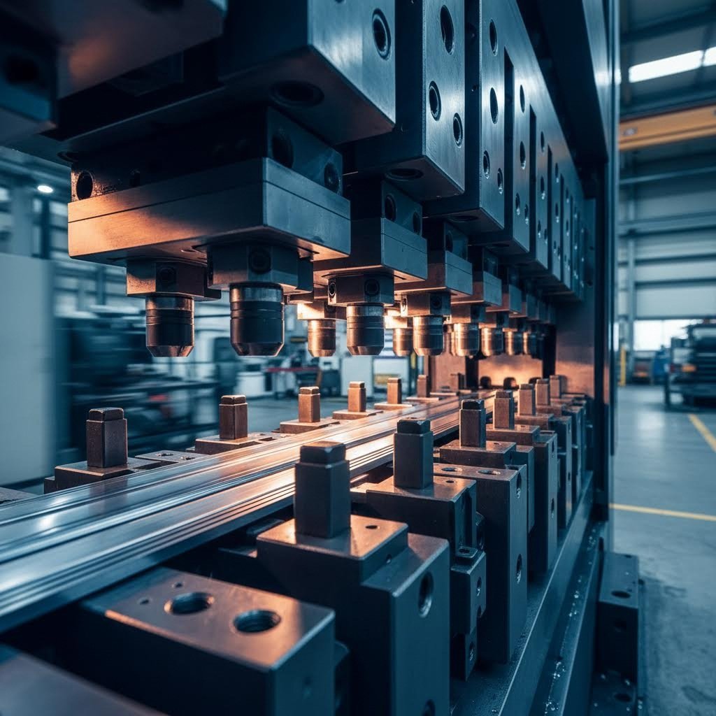
Automotive progressive die design is a specialized engineering discipline focused on creating precision tooling that transforms flat metal strips into complex vehicle components through a series of sequential stamping operations. Unlike single-station dies that perform just one operation per press stroke, progressive dies integrate multiple stations within a single tool, enabling the material to advance or "progress" through cutting, bending, forming, and blanking stages with each stroke of the press. This approach serves as the backbone of high-volume automotive component manufacturing, producing everything from structural brackets and electrical connectors to chassis reinforcements at speeds that would be impossible with conventional tooling methods.
What Makes Progressive Dies Essential for Automotive Manufacturing
When you're facing relentless cost pressure, stringent quality demands, and tight production timelines, why would you choose progressive die stamping over simpler alternatives? The answer lies in understanding how this technology addresses the core challenges of modern automotive supply chains.
A single-station or simple die performs one basic operation, such as punching a hole or making a single bend, with each press stroke. While these tools offer lower upfront costs and faster development times, they require parts to be moved between multiple dies for multi-step operations. This handling adds labor time, increases per-piece costs, and introduces potential consistency issues as part positioning might vary slightly between operations.
Progressive die design eliminates these inefficiencies entirely. Imagine a miniature assembly line packed inside a single, robust die set. Each station performs a specific operation as the metal strip advances automatically through the tool. The die in progressive configurations handles everything from initial pilot hole creation to final part separation, all within one continuous process.
For high-volume automotive production runs reaching tens of thousands to millions of parts, progressive dies deliver finished components rapidly with exceptional consistency, recovering their higher initial investment through dramatically reduced per-piece costs and minimal labor requirements.
How Sequential Stamping Stations Transform Raw Metal into Precision Parts
Picture a coil of metal strip feeding automatically into the first station of a progressive die. With each press stroke, something remarkable happens: the strip advances a precise distance while multiple operations occur simultaneously at different stations throughout the tool.
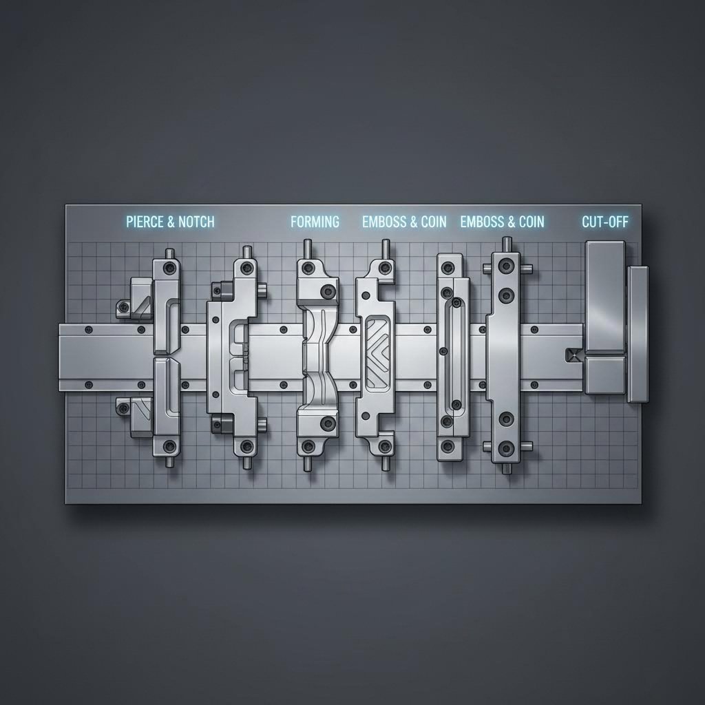
Here's a typical example of stamping progression through a progressive die:
- Station 1: The metal strip enters and pilot holes are punched to establish precise registration for all subsequent operations
- Station 2-3: Additional holes, slots, or features are cut into the strip
- Station 4-5: Forming and bending operations shape the flat material into three-dimensional geometry
- Final Station: The completed part separates from the carrier strip, ready for secondary processing or assembly
This continuous, automated process happening within one die creates remarkable efficiency for automotive applications. Because the material strip is precisely controlled and advances the exact same distance with every stroke, part-to-part consistency reaches levels that manual handling between separate dies simply cannot match.
Progressive die stamping proves particularly valuable for complex automotive components requiring numerous operations. Stage tooling within the die can gradually shape intricate parts over several stations, ensuring that even challenging geometries are achievable with exceptional repeatability. For automotive suppliers facing annual volumes in the hundreds of thousands, this technology transforms what would otherwise be slow, labor-intensive production into a streamlined manufacturing operation capable of meeting OEM delivery schedules while maintaining the tight tolerances modern vehicles demand.

The Complete Progressive Die Design Engineering Workflow
Understanding how progressive dies function is one thing. Knowing how engineers actually design them from scratch is another matter entirely. The stamping die design process follows a disciplined sequence where each phase builds upon decisions made earlier, and mistakes in the initial stages ripple through the entire project. So how do experienced die designers transform a part blueprint into validated tooling ready for production?
From Part Blueprint to Die Concept
Every successful progressive die project begins long before any CAD modeling starts. The foundation lies in thorough part feasibility assessment, where engineers analyze the component geometry to determine whether progressive tooling is even the right approach. They examine material thickness, part complexity, required tolerances, and annual volume requirements to make this critical go/no-go decision.
When designing die solutions for automotive applications, engineers must answer fundamental questions early: How many stations will this part require? What forming operations are needed, and in what sequence? Can the material handle the required deformations without cracking or excessive springback? These answers directly influence every downstream decision in the die for manufacturing development.
The progressive die stamping process demands careful attention to how operations are sequenced across stations. According to The Fabricator, the exact number of steps for a process layout depends on the metal composition, complexity of part geometry, and geometric dimensioning and tolerancing characteristics. For some part shapes, engineers may need to add idle stations that perform no work but allow more room for larger, stronger tooling sections and necessary progressive die components.
Critical Decision Points in the Design Engineering Sequence
The complete die design workflow follows a logical progression where each stage informs the next. Here's how the process typically unfolds:
- Part Feasibility Assessment: Engineers evaluate the component geometry, material specifications, tolerance requirements, and production volumes to confirm progressive tooling suitability and identify potential manufacturing challenges
- Strip Layout Development: The team designs how the metal strip will carry parts through the die, determining carrier type (solid or flex), pitch distance between parts, and material utilization percentages
- Station Sequencing: Operations are assigned to specific stations in optimal order, balancing force distribution, ensuring proper metal flow, and accounting for scrap removal requirements
- 3D Die Modeling: Detailed CAD models capture every punch, die block, guide component, and support structure, establishing precise clearances and tolerances throughout the assembly
- Simulation Validation: CAE software predicts material behavior, identifies potential defects like cracking or excessive thinning, and validates the design before any metal is cut
Why does this sequence matter so much? Because decisions made during strip layout directly constrain what's possible in station sequencing. The carrier design affects how parts move through the tool, which influences where forming operations can occur. As noted in research from ScienceDirect, methods engineers try to determine the minimum number of operations for a given stamping form in order to reduce tooling costs while satisfying objective stamping criteria.
Consider a practical example: an automotive structural bracket requiring multiple bends, several holes, and precise dimensional tolerances. Engineers must decide whether to perform all cutting operations first, then all forming operations, or to intersperse them strategically. Placing a forming operation too early might distort previously punched features. Positioning it too late might not leave enough material for proper carrier strength.
The strip layout phase also requires determining the carrier web type. According to industry guidance, if metal flow occurs during part forming or if height differences exist among die stations, designers typically need a flex or stretch carrier that allows material to flow into the desired part geometry without upsetting the critical pitch distance between each part. This decision cascades through all subsequent design phases.
Early-stage validation through simulation has become essential in modern die design workflows. JVM Manufacturing notes that 3D simulation programs allow engineers to digitally model and simulate the entire design process, predicting how materials will behave under various conditions. This predictive capability helps identify potential issues and optimize die geometry before creating physical prototypes, ultimately saving time and reducing costs.
The engineering workflow concludes with physical die construction and tryout, but the foundation for success is laid in these early design phases. Understanding how each decision affects downstream manufacturing outcomes separates experienced die designers from those still learning the discipline, and it explains why thorough front-end engineering ultimately determines whether a progressive die achieves first-pass approval or requires costly iterations.
Material Selection Criteria for Automotive-Grade Progressive Dies
While engineering workflow determines how a progressive die gets designed, material selection determines whether it will actually work in production. This critical aspect of metal stamping die design directly influences punch clearances, wear rates, springback compensation requirements, and ultimately, die longevity. Yet most discussions about progressive metal stamping gloss over the specific implications different automotive materials have on tooling parameters.
So what happens when you're tasked with designing steel stamping dies for advanced high-strength steels instead of conventional mild steel? Or when lightweighting initiatives demand aluminum components? The answer involves fundamental changes to how you approach every aspect of die design.
High-Strength Steel Considerations for Structural Components
Advanced High-Strength Steels (AHSS) and Ultra High-Strength Steels (UHSS) have revolutionized automotive structural design, but they've also created significant challenges for progressive die engineers. These materials achieve tensile strengths ranging from 500 MPa to over 2000 MPa, meaning the sheet metal hardness sometimes approaches the hardness of the tooling itself.
Consider this reality: according to research from the Auto/Steel Partnership's AHSS Insights, some martensitic steel grades reach Rockwell C values higher than 57. When your sheet metal is nearly as hard as your punches, traditional die materials and clearances simply won't perform.
The higher forces required to form AHSS demand increased attention to several critical areas:
- Punch-to-die clearances: Higher-strength materials require increased clearances compared to mild steels and HSLA grades because the clearance acts as leverage to bend and break the slug out of the sheet metal
- Die material selection: Conventional tool steels like D2 that worked for decades with mild steel often fail prematurely with AHSS grades, sometimes showing 10x reduction in tool life
- Surface treatments: PVD coatings such as TiAlN significantly reduce galling and extend tool life when forming dual phase steels
- Wear resistance: Die wear occurs faster due to the friction and contact pressure from higher-strength materials, requiring more frequent maintenance intervals
Work hardening during stamping further complicates matters. As metal stamping components are formed from AHSS, the material strength increases beyond its initial specification. This dynamic loading accelerates die wear in ways that static calculations don't predict. Additionally, reduced sheet thickness, one of the key drivers for using AHSS in the first place, increases the tendency to wrinkle. Suppressing these wrinkles requires higher blankholder forces, which in turn accelerates wear effects.
The practical solution often involves constructing large forming tools from relatively inexpensive materials like cast iron, then using high-grade tool steel inserts with appropriate coatings in locations subject to severe wear. Powder metallurgy (PM) tool steels offer an optimal combination of impact strength, hardness, and wear resistance that conventional tool steels cannot achieve. In one documented case, switching from D2 to a PM tool steel for forming FB 600 steel increased tool life from 5,000-7,000 cycles back to the expected 40,000-50,000 cycles.
Aluminum Alloy Challenges in Lightweighting Applications
When automotive manufacturers pursue aggressive weight reduction targets, aluminum alloys often replace steel for body panels, closure components, and even some structural elements. However, progressive die design for aluminum requires a fundamentally different approach than steel.
According to AutoForm, stamped parts made from aluminum are more affected by springback than those made from conventional deep-drawn steels. This characteristic demands extensive springback compensation in die geometry, often requiring multiple simulation iterations to achieve parts within required tolerances. The lower elastic modulus of aluminum compared to steel means formed features "spring back" more aggressively toward their original flat state.
An aluminum stamping machine setup faces additional considerations beyond springback. Aluminum's tendency to gall and adhere to tooling surfaces creates different lubrication requirements. The material's lower strength compared to AHSS might seem like an advantage, but aluminum's work hardening characteristics and anisotropic behavior introduce their own forming challenges.
Copper progressive stamping, while less common in automotive structural applications, shares some characteristics with aluminum forming in terms of galling tendencies and lubrication requirements. Electrical connectors and certain specialized components may use copper alloys, requiring similar attention to surface treatments and die material compatibility.
For large structural components that cannot be practically produced in progressive dies, transfer die stamping provides an alternative. This approach moves discrete blanks between stations rather than using a continuous strip, allowing for larger part sizes while maintaining multi-station efficiency.
Material Comparison for Die Design Parameters
Understanding how different materials affect die design parameters helps engineers make informed decisions early in the development process. The following comparison outlines typical automotive applications and the key considerations for each material category:
| Material Type | Typical Automotive Applications | Die Design Considerations | Recommended Clearance Range |
|---|---|---|---|
| Mild Steel (CR/HR) | Non-structural brackets, interior components, simple reinforcements | Standard D2/A2 tool steels acceptable; conventional lubrication sufficient; moderate wear rates | 6-10% of material thickness per side |
| HSLA (340-420 MPa yield) | Cross members, suspension components, seat structures | Enhanced tool steels recommended; increased blankholder forces; surface coatings beneficial | 8-12% of material thickness per side |
| Dual Phase (DP 590-980) | B-pillars, roof rails, side impact beams, structural reinforcements | PM tool steels or coated D2 required; PVD coatings essential; ion nitriding for galvanized materials | 10-15% of material thickness per side |
| Martensitic (MS 1180-1500+) | Door intrusion beams, bumper reinforcements, roll-formed structural tubes | Specialized PM tool steels mandatory; multiple coating layers; frequent maintenance intervals | 12-18% of material thickness per side |
| Aluminum Alloys (5xxx/6xxx) | Hoods, fenders, doors, body side apertures, closures | Significant springback compensation required; anti-galling coatings critical; enhanced lubrication | 8-12% of material thickness per side |
These clearance ranges represent starting points that may require adjustment during development. According to Adient's North American Die Standards, punch clearances should follow material-specific guidelines as a starting point, with adjustments made during development in coordination with the engineering team.
Material thickness limits also vary by grade. While mild steels can be formed at thicknesses up to 6mm or more in certain applications, UHSS grades become increasingly difficult to process above 2-3mm due to the extreme forces required. Aluminum alloys for automotive body panels typically range from 0.8mm to 2.0mm, with thicker gauges reserved for structural castings rather than stamped components.
The interaction between material properties and die design extends beyond clearances. Springback compensation, for instance, must account for both material grade and part geometry. A simple bracket in DP 590 might require 2-3 degrees of overbend compensation, while a complex curved panel could need geometry modifications throughout the entire forming sequence. Simulation validation, discussed in the workflow section, becomes especially critical when working with advanced materials where empirical rules-of-thumb may not apply.
Understanding these material-specific requirements enables engineers to specify appropriate tooling from the outset, avoiding costly iterations and ensuring progressive dies achieve their intended production life. The next step involves translating this material knowledge into optimized strip layouts that maximize efficiency while maintaining the precision automotive OEMs demand.
Strip Layout Optimization and Station Sequencing Strategies
With material selection established, the next critical challenge becomes arranging parts on the metal strip to maximize efficiency while ensuring consistent quality. Strip layout optimization represents where theoretical die design meets practical manufacturing economics. Every percentage point of improved material utilization translates directly to cost savings across high-volume production runs. So how do engineers balance the competing demands of material efficiency, die complexity, and part accuracy?
Maximizing Material Utilization Through Strategic Layout
Strip layout development begins with calculating three fundamental parameters: strip width, pitch distance, and material utilization percentage. These interconnected values determine how much raw material ends up as finished parts versus scrap.
Strip width calculation starts with the part's largest dimension perpendicular to the feed direction, then adds allowances for carrier strips, edge trim, and any bypass notches required for feeding control. Engineers must account for the carrier web that connects parts as they progress through the die. According to Jeelix's progressive stamping guide, the strip remains intact until final cut-off, offering maximum strength and stability to counter feed forces during high-speed operation on a progressive stamping press.
Pitch distance, the amount the strip advances with each press stroke, directly affects material utilization and production rate. Shorter pitch distances improve material usage but may not leave enough room between stations for required tooling. Longer pitches simplify die construction but waste material. Finding the optimal balance requires analyzing part geometry, forming requirements, and station clearances.
Material utilization percentage measures how much of the incoming coil becomes finished product versus scrap. For automotive progressive dies, utilization rates typically range from 60% to 85%, depending on part geometry. Complex shapes with curves and irregular contours naturally yield lower utilization than rectangular parts. When running a metal stamp press machine at hundreds of strokes per minute, even small utilization improvements compound into significant material savings over production runs of millions of parts.
Here are the key strip layout optimization principles that experienced engineers follow:
- Carrier web design: Choose between solid carriers for simple parts or flex/stretch carriers for parts requiring significant metal flow during forming operations
- Nesting opportunities: Evaluate whether parts can be rotated or nested to reduce strip width or improve utilization
- Multi-out configurations: Consider running two or more parts across the strip width for smaller components to multiply output per stroke
- Scrap management: Position operations to ensure clean scrap shedding and avoid slug pulling that could damage parts or tooling
- Edge allowance: Maintain sufficient material at strip edges to prevent edge cracking during forming operations
Bypass notches, sometimes called pitch notches or French notches, deserve particular attention in strip layout design. These small cutouts at one or both strip edges serve multiple critical functions. According to The Fabricator, pitch notches provide a solid stop for the material to prevent overfeeding, which can result in severe die damage and safety hazards. They also create a straight-line cut on incoming material edges, removing any edge camber from the coil slitting process that might cause feeding difficulties.
The placement logic for bypass notches involves strategic positioning at early stations. When used for part registration, two notches on opposite sides of the strip provide optimal balance and feeding accuracy. While some engineers view pitch notches as wasteful material consumption, the reality is more nuanced. A single severe die crash from overfeeding can cost 100 times more than the additional material consumed by pitch notches over an entire production run.
Pilot Hole Placement for Consistent Part Registration
If strip layout determines material efficiency, pilot hole placement determines part accuracy. Every progressive die stampings operation relies on these reference features to maintain precise alignment through dozens of sequential stations.
Pilot holes are punched in the first one or two stations of progressive stamping dies, establishing the absolute reference points for all subsequent operations. As the strip advances, pilot pins mounted on the upper die engage these holes before any forming tools contact the material. The tapered pilot pin design generates lateral forces that nudge the strip into exact X-Y alignment, effectively resetting position with every stroke and breaking any chain of accumulated feeding errors.
Optimal pilot hole positioning follows several guidelines that directly affect part accuracy:
- Proximity to critical features: Position pilots as close as practical to tight-tolerance features to minimize the distance over which positioning errors can accumulate
- Relationship to forming stations: Ensure pilots engage the strip before any forming operations begin each stroke to guarantee proper registration during material deformation
- Carrier web location: Place pilots in the carrier strip rather than within the part envelope whenever possible to avoid leaving witness marks on finished components
- Clearance for pilot pins: Maintain sufficient clearance around pilot hole locations to accommodate the tapered pin diameter during engagement
- Symmetrical placement: Use symmetrically positioned pilots on opposite sides of the strip to provide balanced registration forces
The progressive die itself typically includes multiple pilot stations throughout its length. Initial pilots establish coarse positioning, while secondary pilots at critical forming stations provide localized precision where it matters most. This redundant approach ensures that even if minor feeding variations occur, each sensitive operation receives fresh positioning correction.
Station Sequencing for Complex Automotive Components
Deciding which operations occur at which stations represents one of the most experience-dependent aspects of progressive die design. Poor sequencing can result in part distortion, excessive die wear, or outright forming failures. Effective sequencing balances force distribution, ensures proper material flow, and maintains part accuracy through all operations.
The general principle places cutting operations before forming operations, but reality is more nuanced. Consider these sequencing guidelines for complex automotive parts:
- Pilot holes first: Always establish registration features in the earliest stations before any other operations
- Perimeter trimming before forming: Remove excess material around the part perimeter early to reduce forces during subsequent forming operations
- Progressive forming: Distribute severe bends across multiple stations to avoid cracking, gradually approaching final geometry
- Internal features after forming: Punch holes and slots in formed areas after bending operations when those features must maintain precise location relative to the formed geometry
- Coining and restrike last: Place final sizing operations near the end to establish critical dimensions just before cut-off
Force balancing across progressive dies prevents uneven loading that can cause strip walking, punch deflection, or premature die wear. Engineers calculate the forces generated at each station and arrange operations to distribute loads symmetrically around the die centerline. When heavy operations must occur off-center, counterbalancing features or idle stations help maintain equilibrium.
The spacing between stations also requires careful consideration. Critical forming operations may need extra clearance for larger, stronger punch and die sections. Some progressive stamping die designs incorporate idle stations, positions where no work occurs, specifically to provide room for robust tooling or to allow the strip to stabilize before the next operation.
For automotive structural brackets requiring multiple bends, typical sequencing might proceed as follows: pilot holes in station one, perimeter notching in stations two and three, initial forming in stations four and five, internal hole punching in station six, secondary forming in station seven, coining in station eight, and final cut-off in station nine. This sequence ensures that each operation builds logically on previous work while maintaining the accuracy automotive OEMs demand.
With strip layout optimized and station sequencing established, the next phase involves validating these design decisions through modern simulation tools before committing to physical die construction.
CAD CAM and Simulation Tools in Modern Die Development
You've optimized your strip layout and carefully sequenced every station. But how do you know whether your progressive die metal stamping design will actually work before cutting expensive tool steel? This is where modern simulation technology bridges the gap between theoretical design and production reality. Computer-Aided Engineering (CAE) has transformed die development from an expensive trial-and-error process into a predictive science, allowing engineers to validate designs virtually before committing to physical prototyping.
According to AHSS Insights, computer simulation of sheet metal forming has been in common industrial use for more than two decades. Today's programs closely replicate physical press shop forming operations, providing accurate predictions of blank movement, strains, thinning, wrinkles, and forming severity as defined by conventional forming limit curves. For precision die stamping applications in automotive manufacturing, this capability is no longer optional but essential for competitive die development timelines.
CAE Simulation for Defect Prevention
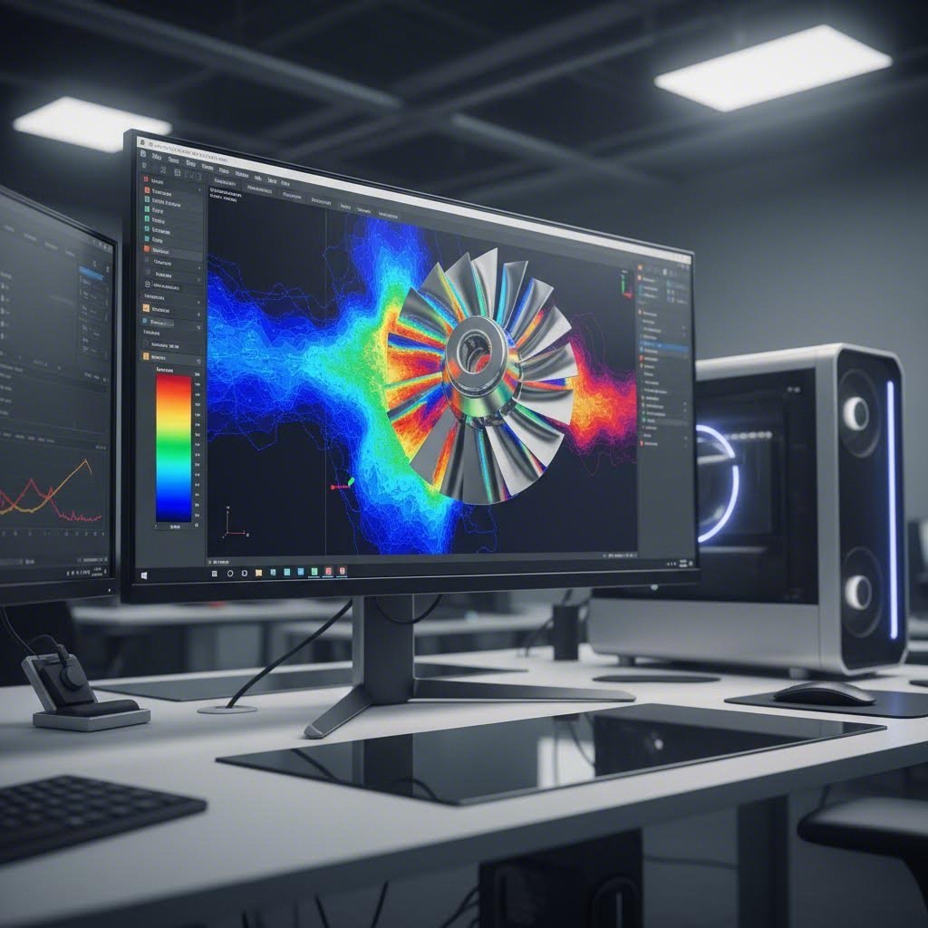
Imagine being able to see exactly where your stamped part will crack, wrinkle, or thin excessively before you've built a single die component. That's precisely what modern forming simulation delivers. These tools predict material flow through each station of a die stamping machine, identifying potential defects that would otherwise only appear during costly physical tryouts.
The value of virtual simulation extends across several critical areas:
- Forming limit analysis: Software evaluates whether material deformation exceeds safe limits, predicting necking and tearing before they occur in production
- Thickness distribution mapping: Simulations reveal where material thins during drawing operations, helping engineers modify radii or add draw beads to control metal flow
- Wrinkle prediction: Virtual analysis identifies areas prone to compression buckling, allowing blankholder force adjustments before physical testing
- Springback calculation: Advanced algorithms predict how formed geometry will deviate from intended shape after tooling releases, enabling compensation in die geometry
- Strain analysis: Principal strain mapping shows stress distribution throughout the part, highlighting areas requiring design modification
Research published in the Journal of Rock Mechanics and Geotechnical Engineering demonstrates how simulation addresses common stamping issues. By varying parameters such as stamping speed, edge pressure, sheet metal thickness, and friction coefficient, engineers can investigate the influence of different process parameters on forming quality and determine optimal settings before physical production begins.
For metal stamping equipment running advanced high-strength steels, simulation becomes even more critical. As noted by AHSS Insights, today's AHSS grades are highly engineered products unique to each steelmaker's production equipment and processing route. Working with accurate, supplier-specific material data in simulations ensures the virtual results match what will happen with production steel on your stamping machine metal forming operations.
Virtual Tryout Methods That Reduce Physical Iterations
Traditional die development required building physical tooling, mounting it in a press, and running actual tryouts to discover problems. Each iteration meant weeks of delay and significant expense. Virtual tryout methods fundamentally change this equation by enabling engineers to iterate digitally in hours rather than weeks.
The simulation approach varies depending on the development stage. Early feasibility analysis uses one-step or inverse codes that rapidly assess whether a stamping can even be manufactured. These tools take the finished part geometry and unfold it to generate a starting blank, calculating strain between the formed and flat shapes. According to AHSS Insights, this approach provides strain along section lines, thinning, forming severity, and blank contour information with reduced computing time.
As development progresses, incremental simulation provides more detailed results. This approach models the actual tools, including punch, die, and blankholder, along with process parameters like blankholder forces, blank shape, and bead geometry. Each increment reflects sheet metal deformation at a different position of the press stroke, with subsequent increments building on prior results.
Key simulation outputs and their design implications include:
- Forming limit diagrams: Visual maps showing strain states relative to material failure limits, guiding decisions about station sequencing and forming severity per operation
- Material flow vectors: Directional indicators revealing how metal moves during forming, informing draw bead placement and blank positioning
- Press loading curves: Force predictions through the stroke cycle, enabling proper press and cushion selection for the die stamping application
- Trim line development: Simulation-derived blank shapes that account for material movement, reducing trim scrap and improving utilization
- Springback compensation geometry: Modified die surfaces that overbend parts to achieve target dimensions after elastic recovery
Some software packages analyze multi-stage forming operations like progressive dies, showing how trimming and other operations at each station affect dimensional precision and springback in subsequent stations. This virtual environment creates a visual record of blank deformation that engineers can trace backward from any defect in the final increment to identify where problems originate.
For automotive OEMs requiring crash simulation data, modern workflows map forming results directly to structural analysis. Previously, crash simulations used initial sheet thickness and as-received yield strength, often producing results that didn't match physical tests. State-of-the-art applications now model forming first, capturing local thinning and work hardening. This point-to-point data feeds directly into crash simulation inputs, producing virtual crash models nearly identical to physical test outcomes.
The practical impact of these tools is substantial. Virtual die tryout allows assessment of part, process, and die design viability before cutting the first hard die. Addressing problems before costly die construction starts leads to improved quality and better resource utilization. For automotive progressive die development, this means designs arrive at physical tryout with far fewer issues, accelerating time-to-production and reducing the engineering iterations that delay program launches.
With simulation validating your design decisions, the next consideration becomes ensuring those designs also incorporate manufacturability principles that extend die life and reduce per-piece costs throughout production.
Design for Manufacturability in Automotive Applications
Simulation confirms your progressive die design will produce parts. But will those parts be cost-effective to manufacture over millions of cycles? This is where Design for Manufacturability (DFM) principles separate adequate tooling from exceptional tooling. Many resources mention DFM in passing, yet few provide the specific geometric guidelines that progressive die manufacturers actually apply when designing stamping components for automotive OEMs.
DFM in progressive die and stamping contexts means deliberately shaping part geometry to reduce tooling stress, minimize wear, and maintain dimensional consistency throughout extended production runs. According to Die-Matic's design fundamentals guide, design isn't just about achieving the desired shape or functionality—it's about creating a part that can be manufactured efficiently, reliably, and cost-effectively. A well-designed component minimizes waste and reduces the need for secondary operations while maintaining structural integrity.
Geometry Modifications That Extend Die Life
Imagine running a progressive die at 400 strokes per minute, 24 hours a day. Every geometric feature on your part impacts tooling wear at this pace. Small design modifications made early can dramatically extend die life and reduce maintenance frequency.
Sharp corners represent one of the most common die-life killers. Internal corners with minimal radii concentrate stress in both the formed part and the tooling. According to Shaoyi's DFM guidelines, internal radii should be at least equal to material thickness, while external radii typically require a minimum of 0.5 times material thickness. These seemingly minor specifications prevent stress concentrations that lead to punch chipping and premature die wear.
Feature spacing also significantly affects tooling durability. When holes or slots are positioned too close together or too near bend lines, the thin die sections between them become fragile and prone to breakage. The electrical stamping process for automotive connectors, for example, requires careful attention to feature spacing because terminal arrays often pack numerous small features into compact envelopes.
Key geometry modifications that extend die longevity include:
- Minimum bend radii: Specify inside bend radii of at least 1x material thickness for mild steels and 1.5-2x for high-strength grades to prevent material cracking and reduce punch stress
- Hole-to-edge distance: Maintain minimum distance of 2x material thickness between hole edges and part edges to ensure adequate material for clean shearing
- Hole-to-bend distance: Position holes at least 2.5x material thickness plus bend radius away from bend lines to prevent hole distortion during forming
- Generous corner radii: Replace sharp internal corners with radii of at least 0.5mm to reduce stress concentration in tooling
- Consistent wall thickness: Avoid dramatic thickness transitions in drawn features to promote even material flow and reduce localized die wear
Draft angles deserve particular attention in progressive stamped automotive parts with formed features. While stamping differs from molding, slight draft on vertical walls facilitates part release from forming punches and reduces galling. For deep-drawn features, draft angles of 1-3 degrees can significantly reduce extraction forces and extend punch life.
Die-Matic notes that draft angles allow stamped parts to be removed from dies smoothly, while radii reduce the risk of cracks and improve overall part durability. Though competitors often mention these principles, specifying actual values—like minimum 1-degree draft for formed pockets deeper than 3x material thickness—transforms vague guidance into actionable design rules.
Tolerance Allocation for Automotive Component Specifications
Tolerance specification in automotive progressive die work requires balancing OEM requirements against process capability. Overly tight tolerances drive up tooling costs, increase scrap rates, and accelerate die wear. Yet automotive applications genuinely require precision on critical assembly features. How do you allocate tolerances wisely?
The key is distinguishing between critical and non-critical dimensions. According to Shaoyi's tolerance guidelines, pierced holes typically achieve ±0.10-0.25mm in standard progressive die operations. Formed heights and bends naturally exhibit more variation due to springback and process dynamics. Specifying tighter tolerances than the process can reliably hold simply increases inspection burden and rejection rates without improving functional performance.
Tolerance stack-up analysis becomes essential when multiple features contribute to assembly fit. Consider a bracket with three mounting holes that must align with mating components. Each hole position has its own tolerance, and these tolerances combine statistically when determining whether the assembly will function. Smart tolerance allocation places tighter bands on datum features while relaxing non-critical dimensions.
For progressive stamped automotive parts, effective tolerance strategies include:
- GD&T datums on formed features: Reference critical tolerances to formed surfaces rather than raw blank edges, since forming can shift edge positions
- Positional tolerances for hole patterns: Use true position callouts referenced to functional datums rather than chain dimensioning that accumulates error
- Profile tolerances for complex contours: Apply profile of a surface controls for curved features rather than attempting to dimension every point
- Bilateral tolerances for symmetrical features: Specify ±0.15mm for holes requiring precise alignment rather than unilateral bands
- Looser bands on non-functional edges: Allow ±0.5mm or greater on trim edges that don't affect assembly or function
Medical progressive stamping applications demonstrate the extreme end of tolerance capability, often requiring ±0.05mm or tighter on critical features. Achieving these specifications demands specialized tooling materials, enhanced process controls, and typically higher piece costs. Automotive applications rarely require such precision, making it important to resist over-specifying tolerances that add cost without functional benefit.
DFM Checklist for Automotive Progressive Die Projects
OEM requirements significantly influence DFM decisions for automotive suppliers. Tier 1 and Tier 2 manufacturers must meet not only dimensional specifications but also material certifications, surface finish requirements, and documented process capability. These requirements cascade into specific die design choices.
Before finalizing any progressive die design for automotive applications, engineers should verify compliance with these manufacturability criteria:
- Material formability: Confirm selected material grade can achieve required bend radii and draw depths without cracking
- Minimum feature sizes: Verify all holes, slots, and tabs meet minimum size rules (typically hole diameter ≥ material thickness)
- Feature spacing: Check that hole-to-hole and hole-to-edge distances meet minimum guidelines for clean shearing
- Bend feasibility: Ensure bend sequences don't create tool interference and allow proper springback compensation
- Tolerance achievability: Confirm specified tolerances align with process capability for the chosen material and operations
- Surface finish requirements: Verify die polishing and maintenance schedules will maintain required surface quality
- Scrap removal: Confirm slug and scrap paths allow clean ejection without jamming or accumulation
- Secondary operations: Identify any features requiring post-stamping operations and factor these into cost and timing
Connecting these principles to manufacturing efficiency metrics clarifies why DFM matters to automotive suppliers. Every geometry modification that extends die life reduces tooling amortization per piece. Every tolerance relaxation on non-critical features reduces inspection time and scrap rates. Every design simplification that eliminates secondary operations cuts direct labor costs.
Progressive die manufacturers working with automotive OEMs understand that first-pass approval rates depend heavily on upfront DFM rigor. Parts designed with manufacturability in mind move through PPAP faster, require fewer die iterations, and achieve production stability sooner. This efficiency translates directly to supplier profitability and customer satisfaction.
With manufacturability principles embedded in your design, the final consideration becomes validating that production parts consistently meet automotive quality standards through rigorous inspection and process control methods.
Quality Control and Validation for Automotive Standards
Your progressive die design incorporates DFM principles and simulation validation. But how do you prove to automotive OEMs that production parts consistently meet specifications? This is where quality control and validation methods become critical differentiators for progressive die tooling suppliers. Automotive manufacturers demand documented evidence that every stamped component meets exacting standards, and the precision die & stamping industry has developed sophisticated approaches to deliver this assurance.
Unlike consumer products where occasional variations might go unnoticed, the automotive metal stamping process produces components where dimensional accuracy directly affects vehicle safety, assembly efficiency, and long-term reliability. A bracket that's 0.3mm out of position might prevent proper weld fitment. A connector terminal with excessive burr could cause electrical failures. These realities drive the rigorous validation frameworks that govern automotive stamping operations.
In-Process Quality Monitoring Techniques
Imagine catching a quality deviation on the third part of a production run rather than discovering it after 10,000 parts have been stamped. That's the promise of in-die sensing and real-time monitoring technologies that have transformed the progressive stamping process from reactive inspection to proactive control.
Modern progressive dies increasingly incorporate sensors that monitor critical parameters during each press stroke. Load cells detect variations in forming forces that might indicate tool wear or material changes. Proximity sensors verify that parts have properly ejected before the next stroke begins. Acoustic sensors can identify the subtle sound signatures of punch breakage or slug pulling before these issues damage subsequent parts.
Statistical Process Control (SPC) implementation converts this sensor data into actionable intelligence. By tracking key dimensions and process parameters over time, SPC systems identify trends before they result in out-of-specification parts. When a dimension begins drifting toward its control limit, operators receive alerts to investigate and correct the root cause.
Critical monitoring points in stamping die manufacturing operations include:
- Forming force variations: Sudden changes may indicate punch wear, material property shifts, or lubrication issues
- Feed accuracy: Sensors verify proper strip advancement to maintain part-to-part consistency
- Die temperature: Thermal monitoring prevents dimensional drift caused by heat buildup during extended runs
- Part presence detection: Confirms proper ejection and prevents double-hits that damage tooling
- Burr height measurement: In-line optical systems flag excessive burr before parts leave the press
The integration of these monitoring capabilities with production data systems enables traceability that automotive OEMs increasingly require. Every part can be linked to specific material lots, process parameters, and quality measurements, creating the documentation trail essential for root cause analysis if field issues ever arise.
Meeting Automotive OEM Validation Requirements
Beyond in-process monitoring, automotive suppliers must demonstrate comprehensive validation before production approval. The Production Part Approval Process (PPAP), developed by the Automotive Industry Action Group (AIAG), provides the framework that governs this validation. According to Ideagen's PPAP guidance, this process should be undertaken before full production begins to help prepare for manufacturing with detailed planning and risk analysis.
First Article Inspection Reports (FAIR) form a crucial component of PPAP submissions. After completing the first production run, manufacturers take one sample product as the 'first article' and conduct thorough inspection to verify that its characteristics align with customer specifications. The FAIR documents all production processes, machinery, tooling, and documentation used to manufacture the first article, providing a baseline measurement that ensures process repeatability.
IATF 16949 certification represents the quality management standard specifically developed for automotive supply chains. For precision die and stamping inc operations serving automotive OEMs, this certification signals commitment to continuous improvement, defect prevention, and reduction of variation and waste. The standard requires documented procedures for everything from incoming material verification to final part inspection.
Critical quality checkpoints throughout die development and production include:
- Design phase: Feasibility reviews, simulation validation, and DFMEA (Design Failure Mode and Effects Analysis) completion
- Die construction: Component inspection, assembly verification, and dimensional validation of all tooling elements
- Initial tryout: First-off part measurement, process capability studies, and engineering approval
- PPAP submission: Complete documentation package including dimensional results, material certifications, and process flow diagrams
- Production monitoring: Ongoing SPC, periodic inspection audits, and tool wear tracking
- Continuous improvement: Corrective action processes, capability trending, and preventive maintenance validation
First-pass approval metrics directly reflect design quality and upfront engineering rigor. When progressive die designs incorporate thorough DFM analysis, simulation validation, and material-appropriate tooling specifications, PPAP submissions proceed smoothly. Conversely, dies rushed into production without adequate validation often require multiple iterations, delaying program launches and eroding supplier credibility.
The documentation requirements for automotive validation extend beyond dimensional inspection. Material certifications must trace to specific heats and lots. Process parameters must be recorded and controlled within specified ranges. Gauge R&R studies must demonstrate measurement system capability. These requirements may seem burdensome, but they provide the foundation for consistent quality that automotive assembly operations depend upon.
With quality systems established and validation processes documented, the final consideration becomes selecting a progressive die partner capable of executing all these requirements while meeting aggressive automotive program timelines.

Selecting the Right Progressive Die Partner for Automotive Projects
You've invested significant engineering effort into designing a progressive die that meets all requirements. But who will actually build it? Selecting the right progressive tool and die partner can mean the difference between a smooth program launch and months of frustrating delays. For automotive suppliers facing relentless OEM pressure on cost, quality, and timing, this decision carries substantial weight.
The challenge is that many progressive die & stamping suppliers look similar on paper. They list similar equipment, claim similar capabilities, and quote comparable prices. So how do you identify partners who will genuinely deliver first-pass success rather than those who will struggle through multiple iterations at your expense?
Engineering Capabilities That Drive First-Pass Success
When evaluating potential progressive tool and manufacturing partners, engineering capability should top your assessment criteria. The quality of upfront engineering directly predicts whether your die will achieve production approval on the first submission or require costly rework.
Look beyond simple equipment lists to understand how potential partners approach the design process. Do they employ dedicated die design engineers, or do they outsource this critical function? Can they demonstrate experience with your specific material grades and part complexity levels? As discussed earlier in this article, advanced materials like AHSS and aluminum alloys demand specialized expertise that not every shop possesses.
Simulation technology represents a key differentiator among progressive stamping and fabrication suppliers. Partners equipped with CAE forming simulation can validate designs virtually before cutting tool steel, dramatically reducing the physical iterations that delay programs. According to Modus Advanced's manufacturing readiness assessment, assessment should begin during initial concept development, not after design completion, and requires input from design engineers, manufacturing engineers, and quality professionals.
Shaoyi exemplifies the engineering-first approach that automotive programs demand. Their integration of CAE simulation supports defect prevention before physical prototyping, while their 93% first-pass approval rate demonstrates the practical results of rigorous upfront engineering. This kind of documented success rate provides concrete evidence beyond marketing claims.
Key engineering questions to ask potential partners include:
- Design team composition: How many dedicated die design engineers do you employ, and what is their average experience level?
- Simulation capabilities: What CAE software do you use for forming simulation, and can you share example validation reports?
- Material expertise: What experience do you have with our specific material grades, particularly AHSS or aluminum if applicable?
- DFM integration: How do you incorporate Design for Manufacturability feedback into customer part designs?
- First-pass metrics: What is your documented first-pass PPAP approval rate over the past two years?
Evaluating Prototyping and Production Capacity
Automotive program timelines rarely accommodate extended development cycles. When engineering changes occur or new programs launch, suppliers must respond quickly. Prototyping speed and production capacity become critical differentiators when schedules compress.
Rapid prototyping capability allows engineering teams to validate designs with physical parts before committing to production tooling. Some prog die suppliers offer prototype turnarounds measured in weeks; others can deliver in days. For programs with aggressive launch dates, this difference matters enormously. Shaoyi's rapid prototyping capability delivers parts in as little as 5 days, accelerating development timelines when programs face schedule pressure.
Production capacity assessment should examine both press tonnage range and facility infrastructure. According to Ultratech Stampings, automotive stamping suppliers need the press tonnage, heavy-duty coil feed lines, and in-house expert tooling minds to handle demanding applications. Their facility handles presses up to 1000 tons with bed sizes up to 148" x 84" and material thickness up to 0.400", demonstrating the scale required for robust structural components.
Beyond raw capacity numbers, evaluate how potential partners manage capacity during peak periods. Do they maintain buffer capacity for urgent requirements, or do they routinely run at maximum utilization? How do they handle the late-add components that inevitably arise during automotive program launches?
Quality certifications provide baseline qualification for automotive work. IATF 16949 certification, as noted by Ultratech, represents the standard set by the International Automotive Task Force for all automotive suppliers to adhere to. This certification ensures rigorous controls throughout the product realization process. Shaoyi's IATF 16949 certification addresses these OEM requirements, providing documented assurance of quality management system compliance.
Partner Evaluation Criteria Comparison
Systematically evaluating potential progressive tool & die partners requires examining multiple capability areas. The following framework helps organize your assessment:
| Capability Area | Key Questions to Ask | Why It Matters for Automotive |
|---|---|---|
| Engineering Depth | How many dedicated die design engineers? What simulation tools are used? What is your first-pass approval rate? | Strong engineering reduces iterations, accelerates PPAP approval, and prevents costly production delays |
| Simulation Technology | Do you perform CAE forming simulation in-house? Can you demonstrate springback compensation capability? | Virtual validation identifies defects before physical tryout, saving weeks of development time |
| Prototyping Speed | What is your typical prototype delivery time? Can you expedite for critical programs? | Rapid prototyping enables faster design validation and supports compressed program timelines |
| Production Capacity | What press tonnage range is available? What are your maximum bed sizes and material thickness capabilities? | Adequate capacity ensures reliable delivery during production ramp-up and peak demand periods |
| Quality Certifications | Are you IATF 16949 certified? What is your PPAP submission success rate? | Certification demonstrates commitment to automotive quality standards and continuous improvement |
| Material Expertise | What experience do you have with AHSS, UHSS, or aluminum alloys? Can you provide reference projects? | Advanced material knowledge prevents tooling failures and ensures proper clearance and wear specifications |
| In-House Tooling | Do you build dies in-house or outsource? What is your tool room capacity? | In-house tooling enables faster iterations, better quality control, and more responsive maintenance |
| Supply Chain Integration | Can you handle secondary operations? Do you offer assembly or sub-component integration? | Integrated capabilities simplify supply chain management and reduce logistics complexity |
When assessing potential progressive tool & manufacturing partners, consider how they handle the entire value chain. As JBC Technologies notes, quality alone isn't a key differentiator when choosing an automotive die partner. Look for suppliers who understand what happens to parts after they land on your dock and can offer suggestions to eliminate waste and non-value steps.
Strategic partners also demonstrate flexibility in handling late-add components to new and existing programs with enhanced speed and cost effectiveness. This responsiveness matters when engineering changes occur or production volumes shift unexpectedly.
Making Your Final Selection
The ideal progressive die partner combines technical capability with responsive service and documented quality performance. They invest in the simulation technology and engineering talent that enables first-pass success. They maintain the certifications and quality systems that automotive OEMs require. And they demonstrate the production capacity and prototyping speed that aggressive program timelines demand.
Site visits provide invaluable insight beyond what proposals and presentations reveal. Observe the facility's organization, equipment condition, and workforce engagement. Review actual PPAP documentation from recent automotive programs. Speak with production operators about typical challenges and how they're resolved.
Reference checks with existing automotive customers offer perhaps the most reliable evaluation data. Ask specifically about responsiveness to problems, communication quality during development, and delivery performance during production. Past performance remains the best predictor of future results.
For automotive suppliers navigating the demands of modern vehicle programs, the right progressive die partner becomes a competitive advantage. Their engineering expertise accelerates development. Their quality systems ensure production stability. Their capacity and responsiveness protect your delivery commitments to OEM customers. Investing time in thorough partner evaluation pays dividends throughout the program lifecycle and across multiple future projects.
Frequently Asked Questions About Automotive Progressive Die Design
1. What is progressive die stamping and how does it work?
Progressive die stamping is a metal forming process where a strip of metal advances through multiple stations within a single die, with each station performing a specific operation like cutting, bending, or forming. With each press stroke, the material progresses forward a precise distance while simultaneous operations occur at different stations. This continuous process produces finished automotive components at high speeds with exceptional consistency, making it ideal for high-volume production of structural brackets, electrical connectors, and chassis components.
2. What are the advantages of progressive die stamping over other methods?
Progressive die stamping offers significant advantages for high-volume automotive production. Unlike single-station dies requiring part handling between operations, progressive dies complete all operations in one continuous process, dramatically reducing labor costs and per-piece expenses. The technology delivers exceptional part-to-part consistency since material positioning is precisely controlled throughout. For production runs reaching millions of parts, progressive dies recover their higher initial investment through faster cycle times, minimal handling, and reduced quality variations that would occur with manual transfers between separate dies.
3. How do I choose the right materials for automotive progressive die design?
Material selection for automotive progressive dies depends on the component's structural requirements and weight targets. High-strength steels like AHSS and UHSS require increased punch clearances (10-18% of thickness), premium tool steels with PVD coatings, and more frequent maintenance intervals. Aluminum alloys demand significant springback compensation and anti-galling surface treatments. Engineers must match die material specifications, clearance calculations, and wear expectations to the specific material grade, as conventional tooling designed for mild steel can fail prematurely when processing advanced materials.
4. What role does CAE simulation play in progressive die development?
CAE simulation has become essential for automotive progressive die development, allowing engineers to validate designs virtually before physical prototyping. Modern simulation software predicts material flow, identifies potential defects like cracking or excessive thinning, calculates springback compensation, and validates station sequencing. This virtual tryout capability reduces physical iterations from weeks to hours, accelerates time-to-production, and significantly lowers development costs. For advanced materials like AHSS, simulation with accurate material data is critical for achieving first-pass success.
5. What certifications should a progressive die supplier have for automotive work?
IATF 16949 certification is the essential quality management standard for automotive progressive die suppliers, ensuring rigorous controls throughout product realization. This certification demonstrates commitment to continuous improvement, defect prevention, and variation reduction. Beyond certification, evaluate suppliers based on documented first-pass PPAP approval rates, CAE simulation capabilities, engineering team depth, and experience with your specific material grades. Partners like Shaoyi combine IATF 16949 certification with advanced simulation technology and 93% first-pass approval rates to deliver reliable automotive tooling.