 Small batches, high standards. Our rapid prototyping service makes validation faster and easier —

Auto stamping parts: DFM tolerances, dies, and press math that pays
Auto Stamping Parts in 2025
Definition of Auto Stamping Parts
When you look at a car’s body, chassis, or even the battery pack of an electric vehicle, have you ever wondered how so many complex metal shapes come together so seamlessly? The answer lies in auto stamping parts. But what is metal stamping exactly, and why does it matter more than ever in 2025?
Auto stamping parts are precision-formed metal components produced by pressing sheet metal into specific shapes using dies and high-tonnage presses, enabling mass production of lightweight, high-strength structures for vehicles.
Automotive Metal Stamping in the Vehicle Lifecycle
Automotive metal stamping is the foundation of modern car manufacturing. As automakers race to deliver safer, lighter, and more cost-effective vehicles, stamping has become the go-to process for producing everything from structural reinforcements to intricate brackets. In 2025, the demand for metal stamping parts grows with trends like electrification and lightweighting. Stamped metal parts are essential for:
- Reducing vehicle weight for better fuel economy and EV range
- Enhancing crash safety by enabling energy-absorbing structures
- Lowering production costs through high-volume repeatability
- Supporting modular designs for rapid vehicle updates
These benefits ripple across the entire vehicle—from the body-in-white and chassis frames to powertrain housings and EV battery enclosures.
Stamped Metal versus Machined Components
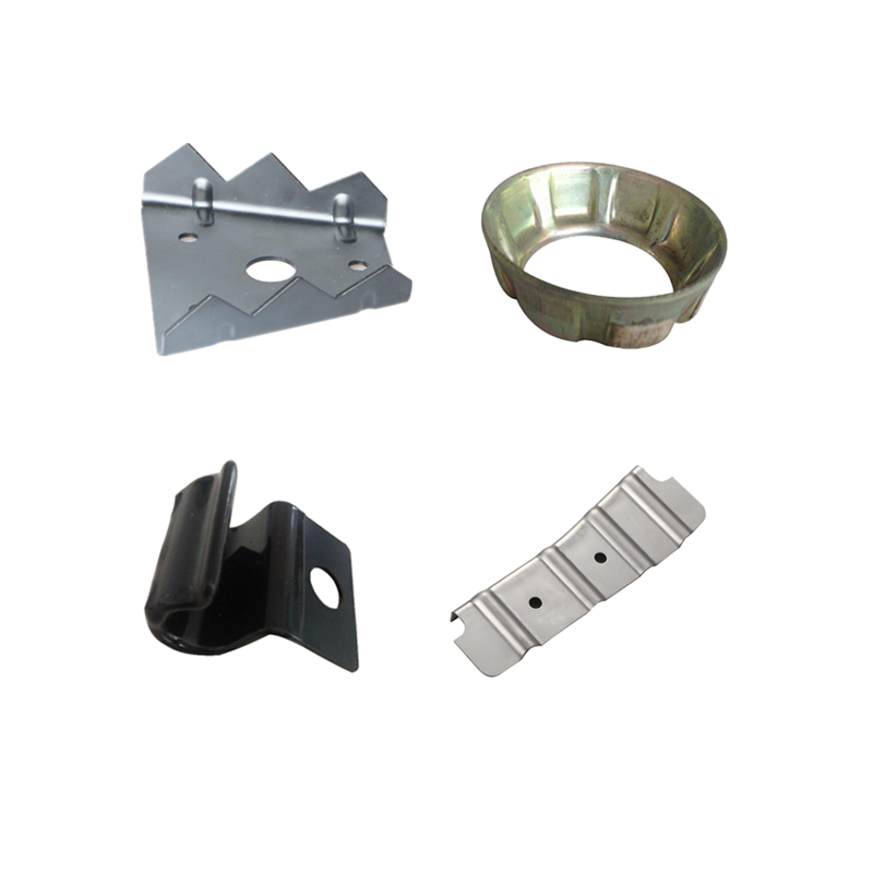
Imagine you need thousands of identical brackets or shields. Machined parts offer precision, but they’re slow and expensive for high volumes. Stamped metal, on the other hand, transforms flat sheets into complex shapes in milliseconds. This difference is why stamped metal parts dominate automotive production, especially where strength-to-weight and cost efficiency are critical.
- Brackets and mounting tabs
- Clips and fasteners
- Reinforcement plates
- Heat and splash shields
- Deep-drawn cans and battery covers
Inside the Stamping Manufacturing Process
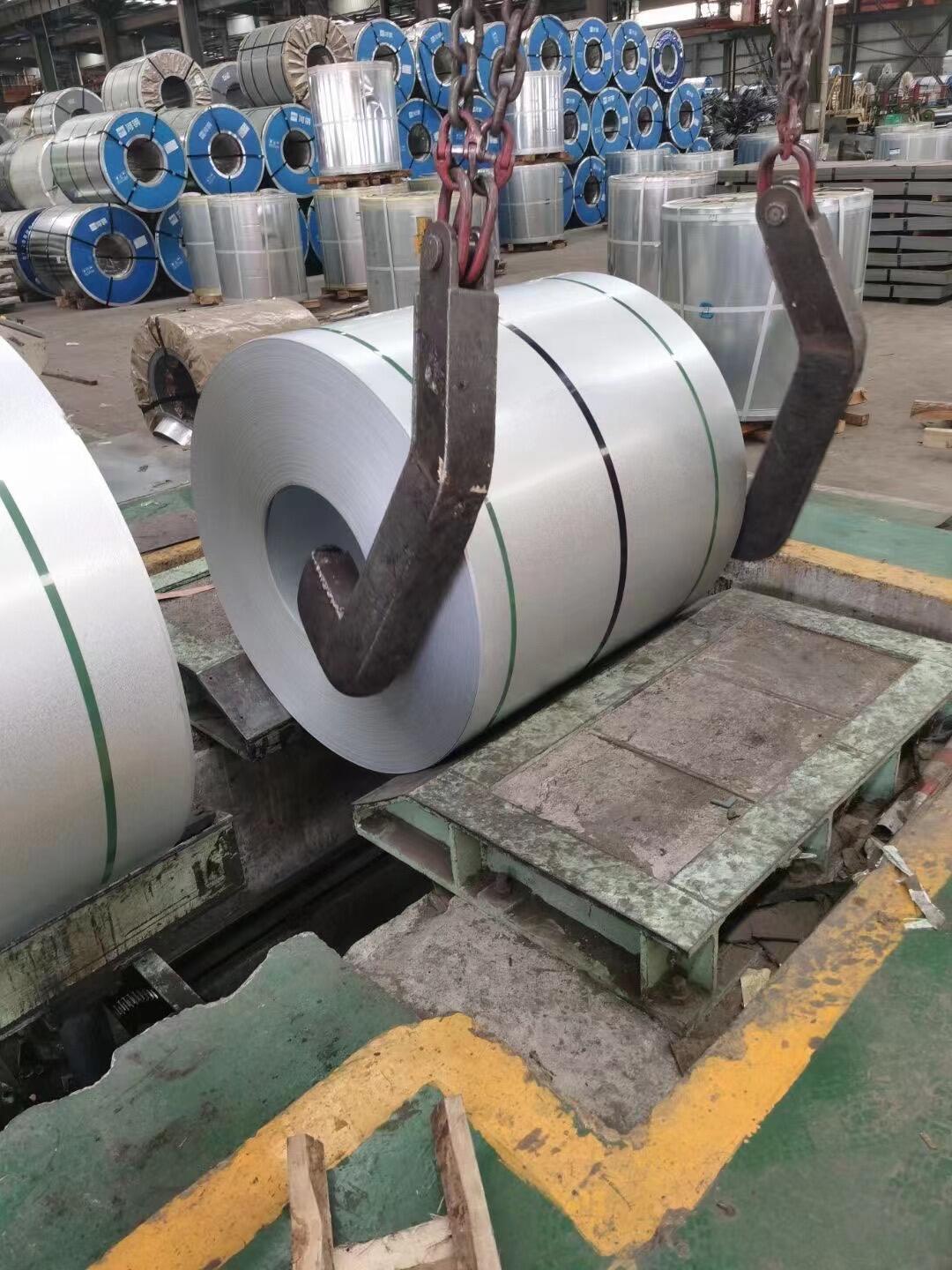
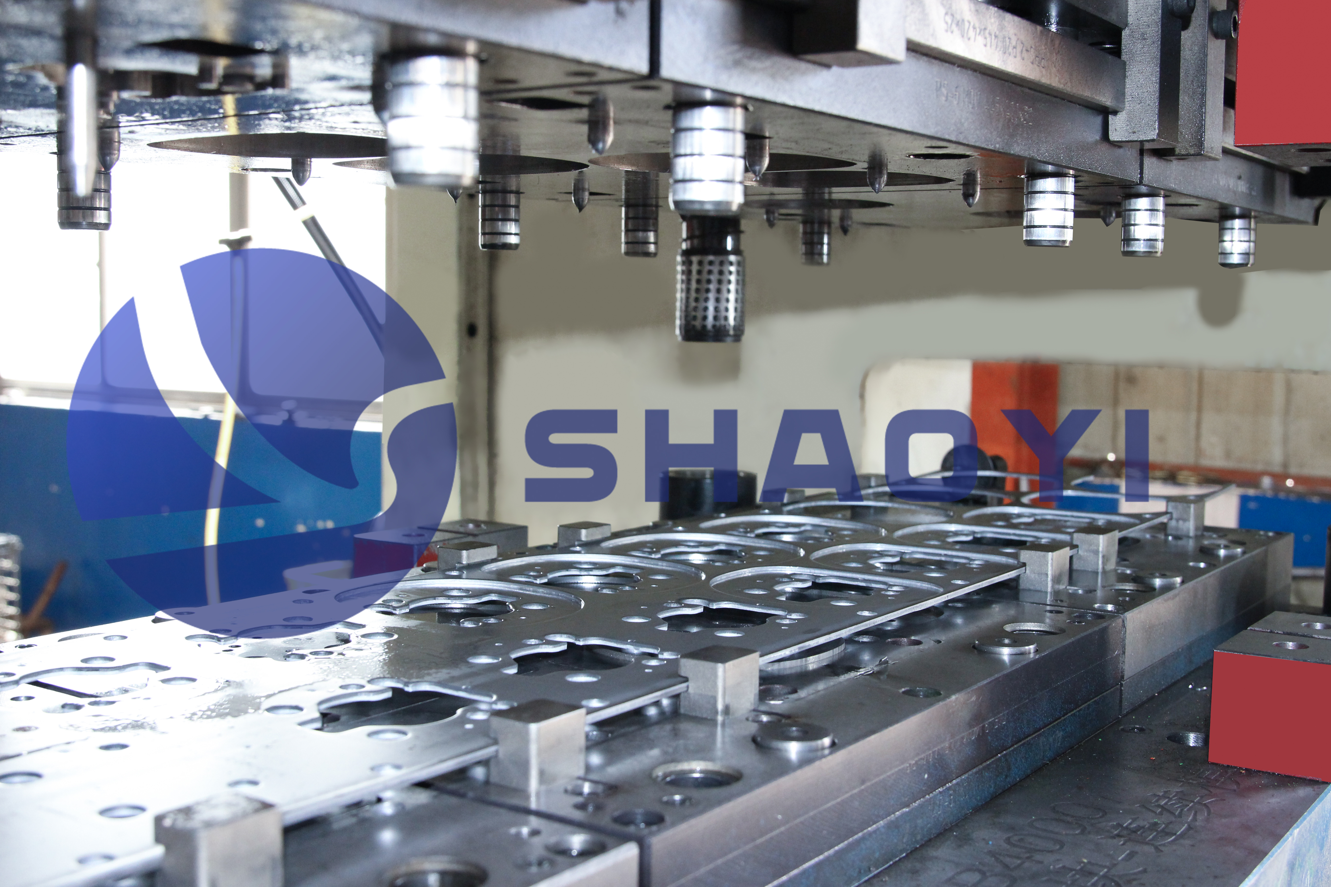
So, what is stamping in practice? The stamping manufacturing process starts with blanking—cutting flat metal shapes from coils or sheets. These blanks then move through progressive or transfer dies, where they’re pierced, bent, formed, and drawn into their final geometry. Secondary operations like tapping, welding, or coating may follow to complete the part.
- Blanking: Cutting the initial flat shape
- Piercing: Creating holes or slots
- Bending/Forming: Shaping the part with precision dies
- Drawing: Forming deep or complex contours
- Secondary Ops: Tapping, welding, coating, or assembly
Throughout, rigorous quality systems—such as IATF 16949—ensure parts meet the strict automotive standards for safety and reliability. For advanced materials, research like the latest SAE studies on springback in high-strength steels guides process optimization.
As you plan your next RFQ or sourcing initiative, working with an experienced supplier is crucial. For those seeking a proven partner, auto stamping parts from Shaoyi Metal Parts Supplier offer a comprehensive solution—combining engineering, manufacturing, and quality assurance under one roof.
In short, auto stamping parts are the unsung heroes enabling tomorrow’s vehicles to be lighter, safer, and more affordable. Understanding their role and the process behind them sets the stage for smarter design and sourcing decisions throughout the automotive supply chain.
Materials and Sustainability Made Practical
Material Selection for Performance and Cost
When you’re designing steel stamping parts or aluminium stamping parts, the first question is often: which metal is right for the job? Imagine you’re tasked with a lightweight bracket for an EV, or a high-strength reinforcement for a crash zone. Each material—low-carbon steel, high-strength low-alloy (HSLA), aluminum alloys, or stainless steel—offers unique benefits and tradeoffs for metal stamping components.
| Material Type | Typical Tensile/Yield (MPa) | Elongation (%) | Recommended Thickness (mm) | Formability Notes | Springback Tendency | Coating Compatibility |
|---|---|---|---|---|---|---|
| SAE 1008/1010 (Low-Carbon Steel) | 270/170 | 35–40 | 0.6–2.5 | Excellent for deep drawing; low cost | Low | Zn, Zn-Ni, E-coat |
| HSLA 340–550 | 340–550/250–400 | 16–25 | 0.7–2.5 | Higher strength, moderate formability | Moderate to High | Zn, E-coat |
| 5052/6061 Aluminum | 210–290/130–270 | 10–20 | 0.8–3.0 | Good for lightweight, corrosion-resistant parts | High | Anodize, E-coat |
| 304/430 Stainless Steel | 520–750/215–450 | 35–50 | 0.5–2.0 | Excellent corrosion resistance; higher cost | Moderate | Rarely needed; can be passivated |
For example, stamped steel parts made from SAE 1008/1010 are ideal for brackets and low-stress components due to their low cost and high formability. HSLA steels, such as 340–550 MPa grades, excel in safety-critical structures, offering weight savings without sacrificing strength. If weight is your top priority, stamped aluminum parts (like 5052 or 6061) deliver significant mass reduction, especially in EVs and body panels. Stainless steels, such as 304 or 430, shine in harsh environments where corrosion resistance is non-negotiable, such as exhaust shields or battery enclosures.
Sustainability and Recyclability in Automotive Stamping
Sounds complex? It gets even more interesting when you factor in sustainability. Today’s automotive industry is laser-focused on end-of-life recyclability and minimizing production waste. Steel and aluminum both boast high recyclability rates—steel is recycled at rates above 90%, while aluminum recycling saves up to 95% of the energy required for primary production. The use of closed-loop scrap systems in steel sheet stamping and aluminum operations helps keep valuable material in circulation and reduces environmental impact.
- Steel: Near-complete recyclability; closed-loop scrap systems common in major stamping plants
- Aluminum: High value in scrap; in-plant segregation and melt-back loops standard
- Stainless: 100% recyclable; often sourced with recycled content
- In-press scrap reduction: Optimized nesting and blank design reduce trim scrap, boosting coil yield
Optimizing metal for metal stamping means balancing performance, cost, and environmental responsibility—an equation that’s central to automotive supply chains in 2025.
Coatings and Corrosion Management in Harsh Environments
Ever wondered why some metal stamping components last for decades, even in tough climates? The answer often lies in the right choice of coatings. Zinc (Zn) and zinc-nickel (Zn-Ni) electroplating are widely used for steel stamping parts to prevent rust, while e-coat (electrophoretic paint) adds another layer of defense, especially for underbody and structural applications. For aluminium stamping parts, anodizing enhances corrosion resistance and appearance, while stainless steels typically require no additional coating due to their inherent properties.
Coating selection is not just about protection—some coatings can affect formability and springback during stamping. For example, thick zinc layers may reduce ductility, so it’s critical to specify compatible coatings early in the design phase. Referencing standards like ASTM A1008/A1011 for steel and ASTM B209 for aluminum ensures you’re working with materials and coatings that meet automotive expectations.
By understanding the strengths and limitations of each material and their coatings, you’ll be able to specify auto stamping parts that hit the mark for cost, performance, and sustainability. Next, we’ll dive into the DFM and tolerancing rules that help you avoid costly rework and keep your stamping projects on track.
DFM and Tolerancing That Prevent Rework
DFM Rules That Reduce Tooling Cost
Ever wondered why some sheet metal stampings breeze through production while others rack up costly tool changes and scrap? The answer often lies in design-for-manufacturability (DFM) basics. When you apply proven DFM rules up front, you cut risk, control cost, and ensure your precision metal stamping parts are right the first time.
Let’s break down the most critical numeric guidelines for metal stamped parts—the kind that make or break a stamping program:
| Feature | Recommended Rule of Thumb | Notes |
|---|---|---|
| Minimum Hole Diameter (mild steel) | ≥ 1.2 × material thickness (t) | Prevents punch breakage and slug pulling |
| Minimum Web/Slot Width | ≥ 1.5 × t | Ensures strength between features |
| Minimum Corner Radius | ≥ 0.5 × t | Reduces stress, extends die life |
| Bend Radius (mild steel) | 1.0–1.5 × t | Prevents cracking, eases forming |
| Bend Radius (stainless) | 1.5–2.0 × t | Accounts for lower ductility |
| Bend Radius (aluminum) | 0.8–1.0 × t | Aluminum is more ductile, but sensitive to cracking if too sharp |
| Draw Depth (single draw) | ≤ 2.0 × punch diameter | Deeper draws require multiple stages |
| General Tolerance (pierced features) | ±0.10–0.25 mm | Progressive dies can consistently hold this range |
Following these guidelines not only protects your tooling investment but also boosts part consistency across large volumes of stamped parts.
Tolerancing Strategies for Stamped Parts
Sounds complex? It doesn’t have to be. When you’re defining tolerances for sheet metal stampings, the key is to focus on what matters functionally. Start with critical features—like holes for fasteners or datums for assembly—and allow looser tolerances elsewhere. This approach reduces rework and keeps costs in check.
- Bilateral tolerances (±): Best for features that must stay centered, like slots or holes aligning with mating parts.
- Unilateral tolerances (+0/–X): Use where only one direction matters, such as edge clearance to avoid interference.
- Datum strategy: Always tie key tolerances to functional datums—formed surfaces, not raw blanks, for best repeatability.
For pierced holes, a general tolerance of ±0.10–0.25 mm is typical. For formed heights and bends, allow a bit more—springback and process variation are natural in metal stamped parts.
GD&T Callouts That Matter Most
Geometric Dimensioning and Tolerancing (GD&T) is your friend—if you use it wisely. For precision metal stamping parts, the most valuable GD&T callouts are:
- Position: Controls hole location relative to datums. Typical band: 0.2–0.5 mm for progressive dies.
- Flatness: Ensures mating surfaces are within spec. 0.3–0.5 mm is common for large stampings.
- Perpendicularity: Critical for tabs or features that must stand proud from the base.
- Profile: Useful for complex contours, especially in outer panels or shields.
When in doubt, reference the process capability of your stamping line. Overly tight bands on non-critical features drive up cost and may not be sustainable in volume production.
Common DFM Pitfalls to Avoid
- Specifying tight tolerances on non-functional edges
- Neglecting reliefs at bends, which can cause tearing or wrinkling
- Ignoring burr direction—can affect assembly or safety
- Placing holes too close to bends or part edges
- Assuming all features can be held to machined-part tolerances
"The best designs for stamped parts balance precision where it counts and flexibility everywhere else."
By applying these DFM and tolerancing strategies, you’ll notice fewer surprises on the shop floor and a smoother path from design to mass production. Next, we’ll get hands-on with die and press parameters—so you can translate great design into reliable manufacturing.
Tooling and Press Parameters That Matter
Press and Die Selection for Reliability
Ever wondered why some stamping lines run smoothly shift after shift, while others struggle with downtime or inconsistent quality? The answer often lies in choosing the right automotive stamping dies and matching them with the right press. When you’re working with auto stamping parts, you’ll encounter several die types—each with its own sweet spot:
- Blanking dies: Cut flat shapes from coil or sheet.
- Piercing dies: Punch holes or slots with precision.
- Forming dies: Bend or shape the blank into its final geometry.
- Deep drawing dies: Pull metal into complex, deep shapes—think battery cans or oil pans.
- Progressive dies: Combine multiple operations in one tool, moving the part from station to station with each press stroke. Ideal for high-volume, small-to-medium complexity parts.
- Transfer dies: Move parts between separate dies for each step—best for large, complex, or deep-drawn parts.
- Compound dies: Perform several cutting and forming steps in a single press stroke; great for simple, high-volume shapes.
Choosing between these depends on part geometry, volume, and the balance of cost versus flexibility. For instance, progressive dies excel in high-speed runs, while transfer dies handle larger or more complex stampings.
Critical Parameters by Process Type
Sounds complex? Let’s break it down with some practical math and rules of thumb. Every automotive stamping press must deliver enough force (tonnage) to cut and form the part without overloading the equipment or the die. Here’s how you estimate what you need:
| Parameter | Typical Value/Formula | Notes |
|---|---|---|
| Tonnage Estimate | Perimeter × Thickness × Shear Strength + 10–20% safety margin |
Calculate for the most demanding operation |
| Punch–Die Clearance per Side (% thickness) | Mild steel: 5–10% Stainless: 10–15% Aluminum: 6–10% |
Too tight = tool wear; too loose = burrs |
| Blank-Holder Force (BHF) | 20–40% of draw force | Critical for deep drawing to prevent wrinkling |
| Typical Strokes Per Minute (SPM) | Progressive: 30–80 Deep draw: 10–30 |
Higher SPM = higher output, but watch for complexity limits |
Imagine you’re running a machine stamping line: A bracket with a 400 mm perimeter, 1.5 mm thick, and a shear strength of 400 MPa would need roughly 240 kN (or 24 tons) plus safety margin. Always select a press that offers at least 10–20% more capacity than your calculated max to account for dynamic loads and tool wear.
Lubrication, Wear, and Die Life Planning
Now, let’s talk about keeping your automotive stamping dies running for the long haul. Lubrication isn’t just about making parts shiny—it’s essential for reducing friction, controlling heat, and preventing galling (especially with aluminum or high-strength steels). The right lubricant also helps extend die life and maintain consistent part quality throughout the automotive metal stamping process.
- Die maintenance intervals: Regular cleaning and inspection—often every 10,000 to 50,000 cycles depending on material and complexity.
- Coating options for punches: Titanium Nitride (TiN) and Diamond-Like Carbon (DLC) coatings reduce wear and sticking, especially in high-volume runs.
- Common die failure modes: Edge chipping, galling, cracking, and excessive wear—watch for these during scheduled checks.
Industrial metal stamping machines are only as reliable as their weakest die or punch. Proactive maintenance, combined with smart material and lubricant choices, keeps your line running and your parts in spec.
By mastering these press and die fundamentals, you’ll ensure your automotive stamping process is robust, repeatable, and ready for anything the production floor throws at it. Next, we’ll explore the quality systems and PPAP documentation that underpin every successful automotive stamping program.
What Buyers and Engineers Need to Know?
PPAP Documentation Essentials
When you’re sourcing auto stamping parts, how do you know your parts will meet tough automotive standards every time? That’s where the Production Part Approval Process (PPAP) steps in. PPAP is the industry’s structured method for demonstrating that your supplier’s process can reliably deliver quality stamped metal assemblies—not just once, but across every production run. If you’re new to PPAP, think of it as the evidence package that proves your stamping manufacturer is ready for mass production.
- Level 1: Part Submission Warrant (PSW) only. Used for simple, low-risk parts—just the summary form is submitted.
- Level 2: PSW plus product samples and limited supporting data. Typical for less complex production metal stamping projects.
- Level 3: PSW with product samples and full supporting data—dimensional results, material certs, process capability evidence. This is the default for most automotive metal stamping companies and is almost always required by OEMs for new or critical parts.
- Level 4: PSW and other requirements as defined by the customer. Used for unique situations or special customer needs.
Each level increases in documentation depth and scrutiny. Most automotive buyers expect Level 3 as the baseline for any new or safety-critical auto stamping parts program. Why? Because it provides full traceability and proof that the process is robust.
What OEMs Expect From Suppliers
Sounds like a lot? It is, but it’s also your roadmap for risk-free launches. Here’s what you’ll typically need to submit or review as part of a PPAP package:
- Part Submission Warrant (PSW): The official sign-off document summarizing the submission.
- Design Failure Mode and Effects Analysis (DFMEA): Risk analysis for the part’s design.
- Process Failure Mode and Effects Analysis (PFMEA): Risk analysis for the manufacturing process.
- Control Plan: The blueprint for quality checks throughout production.
- Measurement System Analysis (MSA): Gage R&R studies to verify measurement accuracy and repeatability.
- Statistical Process Control (SPC): Data showing the process is stable (Cpk/Ppk targets typically ≥1.33).
- Dimensional Reports: Results from measuring all key features on multiple parts.
- Material Certifications: Proof that all materials meet required specs (steel, aluminum, coatings, etc).
- Process Flow Diagram: Visual map of every step from raw coil to finished part.
- Initial Process Studies: Early production runs demonstrating process capability.
- IMDS Entries: International Material Data System for environmental compliance.
Imagine you’re launching a new bracket for an EV battery pack. Your customer will want to see not just a finished part, but the full story—from design risk analysis to measurement system capability. This transparency is what sets top automotive metal stamping companies apart.
Standards That Govern Automotive Stamping Quality
Ever wonder why so many supplier audits ask about IATF 16949 or ISO 9001? The answer is simple: these frameworks guarantee a consistent, industry-accepted approach to quality management for every stamped metal assemblies program.
- IATF 16949: The global standard for automotive quality management, built on ISO 9001 but tailored for the unique needs of automotive manufacturers. It covers everything from risk management to process control and continuous improvement. Certification is often a prerequisite for doing business with major OEMs.
- ASTM and SAE Standards: These organizations set the technical requirements for materials, testing, and performance. For example, ASTM standards define how to test metal strength or corrosion resistance, while SAE standards set best practices for automotive engineering and process control.
By referencing these standards in your drawings and control plans, you create a common language that ensures quality—no matter where your production metal stamping is done.
PPAP Checklist for a Smooth Launch
- PSW (Part Submission Warrant)
- DFMEA / PFMEA
- Control Plan
- Measurement System Analysis (MSA) / Gage R&R
- SPC data (Cpk/Ppk targets)
- Dimensional reports
- Material certifications
- Process flow diagram
- Initial process studies
- IMDS entries
Bringing it all together, a robust quality system and thorough PPAP submission are your best defense against costly surprises, delays, or recalls. With these foundations in place, you’re ready to focus on inspection and metrology—the next vital step for ensuring every stamped part meets spec, every time.
Inspection and Metrology That Drive Capability in Automotive Metal Stamped Parts
Where to Focus Inspection Effort
When you’re producing thousands of metal stamping parts for automotive applications, how do you know each one will fit and function perfectly? The answer lies in a strategic inspection plan that targets the features most critical to assembly and performance—without overburdening your process with unnecessary checks. But what should you measure, how often, and with what equipment?
- Pierced hole size and location: Use vision-based Coordinate Measuring Machines (CMMs) or 3D laser scanners to verify diameter and position, ensuring holes align with fasteners and mating parts. This is vital for every metal stamped part used in assemblies.
- Form height and geometry: Height gauges and custom indicator fixtures confirm that bends and drawn features meet spec, preventing fit-up issues in brackets or shields.
- Flatness: Place the stamped metal component on a granite surface plate and check with feeler gauges. This quick method catches warping before it causes assembly headaches.
- Edge burr and finish: Profilometers or simple tactile checks help spot sharp edges or excessive burrs, which can affect safety or downstream assembly.
- Springback: Go/no-go functional gauges or 3D scanning compare formed parts to CAD, ensuring springback stays within tolerance—especially important for high-strength or complex geometries.
Advanced 3D scanning solutions, like those described in the SCANOLOGY case study, are increasingly used to capture full-field data on complex automotive metal stamped parts, enabling rapid alignment, springback analysis, and trimming line inspection. This technology helps pinpoint deviations quickly, reducing downtime and scrap.
GD&T Interpretation for Stampings
Sounds overwhelming? Here’s a practical approach: focus your tightest tolerances and most advanced measurement methods on features that affect assembly or function. Use bilateral tolerances (±) for holes and slots that must align precisely, and unilateral tolerances (+0/–X) for edges where only one direction matters—like clearance to avoid interference. For complex shapes, always read GD&T (Geometric Dimensioning & Tolerancing) in the context of formed—not flat—geometries. That means measuring features after forming, not just on the blank.
Don’t forget about feature “stack-up”—the way small variations in each feature can add up across a metal stamping part. By tying your critical dimensions to functional datums (formed surfaces, key holes, or tabs), you minimize variation where it matters most. Avoid referencing raw blanks as datums, since forming can shift their position and create hidden errors.
“Stabilize datums to formed features, not blanks, to control functional dimensions.”
Metrology by Phase: Prototype, Launch, and Mass Production
Inspection requirements shift as you move from prototype to production. During prototyping, you’ll rely on detailed CMM or 3D scans to validate every feature and catch unexpected deviations. At launch, sampling plans (such as ISO 2859 or ANSI Z1.4) help balance thoroughness and speed—measuring a statistically valid subset of parts to confirm process stability. In mass production, inline gauges and Statistical Process Control (SPC) keep an eye on high-risk characteristics, triggering alerts if trends drift out of spec.
- Prototype: 100% inspection of all features with CMM/3D scanning; detailed dimensional reports for each metal stamped part.
- Launch: Sampling per ISO 2859/ANSI Z1.4; focus on key features and datums; SPC charts for critical dimensions.
- Mass Production: Inline or at-press gauges for holes, heights, and forms; periodic flatness and burr checks; automated vision systems for complex stamped metal components.
Imagine you’re ramping up a new bracket: Early builds get measured exhaustively. Once capability is proven, you shift to sampling, with inline SPC watching for tool wear or drift. This staged approach keeps quality high and costs controlled.
By combining targeted inspection, smart GD&T interpretation, and phase-appropriate metrology, you’ll ensure every automotive metal stamped part meets spec—without slowing down your line. Up next, we’ll look at real-world examples to see how these principles play out in actual automotive stamping projects.
Realistic Examples That Guide Design Choices
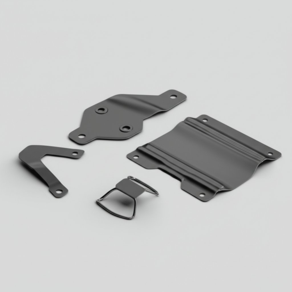
When you’re trying to bridge the gap between design theory and real-world manufacturing, nothing beats concrete examples. Ever wondered how a small bracket compares to a deep-drawn EV shielding can, or what makes a spring clip different from a structural panel in terms of custom automotive metal stamping? Let’s break down four of the most common automotive stamping families—so you can see how choices in size, material, process, and tolerances play out on the shop floor.
Bracket Case Study: Small Progressive-Die Bracket
Imagine you’re designing a mounting bracket for a vehicle’s HVAC system. The priorities? High repeatability, moderate strength, and cost efficiency. This is a textbook case for automotive components progressive stamping:
| Part Type | Typical Size (mm) | Material | Key Tolerances | Die Type | Cycle Time | Coating/Finish | Secondary Ops |
|---|---|---|---|---|---|---|---|
| Bracket | 60 × 40 × 2 | HSLA 340, t = 2.0 | ±0.15 mm (holes), flatness 0.3 mm | Progressive | 40–60 SPM | Zn or E-coat | Tapping, deburr |
You’ll notice that progressive dies allow for high-speed production and tight tolerances on pierced features. This approach is ideal for brackets and similar custom stamping parts that need to be produced in the tens or hundreds of thousands with minimal variation.
Clip Case Study: High-Volume Spring Clip
Now, picture a spring clip used to hold wiring harnesses in place. Here, material selection and forming precision are crucial for long-term performance. The process often leverages fastener metal stamping in progressive dies:
| Part Type | Typical Size (mm) | Material | Key Tolerances | Die Type | Cycle Time | Coating/Finish | Secondary Ops |
|---|---|---|---|---|---|---|---|
| Spring Clip | 25 × 15 × 1.0 | Spring Steel, t = 1.0 | ±0.10 mm (slots), flatness 0.2 mm | Progressive | 70–100 SPM | Zn-Ni, Black Oxide | Heat treat, deburr |
With high-volume runs and narrow tolerances, these clips show how custom automotive metal stamping delivers both speed and repeatability. The heat treatment step is essential for achieving the required spring properties.
Structural Panel Case Study: Outer Body Reinforcement
What about large, load-bearing parts? Take an outer body reinforcement panel—critical for crash safety and rigidity. Here, automotive sheet metal parts demand robust dies and careful process control:
| Part Type | Typical Size (mm) | Material | Key Tolerances | Die Type | Cycle Time | Coating/Finish | Secondary Ops |
|---|---|---|---|---|---|---|---|
| Body Reinforcement Panel | 600 × 400 × 1.2 | HSLA 440, t = 1.2 | ±0.25 mm (profile), flatness 0.5 mm | Transfer | 15–25 SPM | Zn, E-coat | Stud weld, spot weld |
Transfer dies are preferred for these large, complex forms, allowing for deeper draws and more precise control of geometry. These panels are a great example of stamped mechanical part assembly—often requiring spot welding or the addition of fasteners in secondary operations.
Deep-Drawn Cup Case Study: EV Shielding Can
Finally, consider an EV battery shielding can—a deep-drawn component with strict EMI (electromagnetic interference) requirements. Deep drawing is the go-to process for this type of custom stamping parts:
| Part Type | Typical Size (mm) | Material | Key Tolerances | Die Type | Cycle Time | Coating/Finish | Secondary Ops |
|---|---|---|---|---|---|---|---|
| EV Shielding Can | 80 × 80 × 30 | 304 Stainless, t = 0.8 | ±0.20 mm (draw depth), flatness 0.4 mm | Deep Draw | 10–20 SPM | Passivated | Trim, deburr |
Deep drawing requires careful control of material flow and blank-holder force. Stainless steel is selected for its corrosion resistance and shielding properties, and the process is validated through pilot runs before ramping up to full production.
Prototype to Production: The Validation Path
- Start with soft tools (simple, low-cost dies) for prototypes and early geometry checks.
- Run pilot builds to validate forming, draw, and bead geometry—adjust as needed before committing to hard tooling.
- Apply gateway metrics: Cpk ≥ 1.33 on key features, scrap rates below 2% before full launch.
- Scale up to production tooling only after meeting capability, quality, and cost targets.
This approach not only reduces risk but also saves time and money by catching issues early—before they become expensive problems in mass production.
By grounding your decisions in real data and proven process paths, you’ll design custom automotive metal stamping projects that deliver on function, quality, and cost. Next, we’ll dive into troubleshooting—so you know what to watch for and how to fix defects before they impact your line.
Troubleshooting Defects with Root Cause Clarity in Stamping Manufacturing
Defect Patterns and Fast Fixes
When you walk a stamping line, you’ll notice that certain defects crop up again and again—burrs, wrinkles, springback, and more. But which ones matter most, and how do you fix them quickly? Whether you’re in the early startup phase or deep into steady-state production, understanding common stamping manufacturing issues—and acting fast—can be the difference between high yield and costly rework.
| Defect | Symptom | Likely Root Cause | Corrective Action | Priority/Impact | Where to Measure |
|---|---|---|---|---|---|
| Burrs (excessive/uneven) | Sharp edges, difficult assembly, safety concerns | Insufficient punch–die clearance, dull or chipped punches | Regrind punches, increase clearance by 2–3% thickness (t) | High—affects part function and safety | All cut edges, especially after piercing |
| Springback | Parts don’t hold intended shape, assembly misalignment | High-strength materials, sharp radii, insufficient overbend | Add overbend, restrike operation, adjust draw beads | High—impacts fit and downstream assembly | Bends, drawn forms, critical geometry |
| Wrinkling | Wavy or rippled surfaces in formed areas | Low blank-holder force, poor lubrication, excessive material | Increase blank-holder force by 10–20%, optimize lubrication | Medium—may cause rework or scrap | Drawn panels, deep forms |
| Tearing | Cracks or splits, especially in corners or deep draws | Excessive draw depth, tight radii, poor material flow | Increase radii, add draw beads, review material grade | High—leads to immediate scrap | Deep-drawn features, corners |
| Dimensional Shift | Parts out of tolerance, holes misaligned, inconsistent fit | Die misalignment, worn guides, thermal growth | Realign die, replace wear plates, monitor press temperature | High—affects assembly and function | Critical datums, hole locations |
Stabilizing a Stamping Line Under Pressure
Sounds overwhelming? Imagine a new launch where every minute of downtime costs real money. The fastest way to stabilize a stamping line is to prioritize fixes that deliver the biggest yield improvement. Focus first on high-impact, high-frequency issues—like burrs or dimensional drift—before chasing cosmetic flaws. Use structured troubleshooting to separate startup glitches (like lube starvation or die seating) from chronic, steady-state problems (such as tool wear or misalignment).
Don’t forget, the metal stamping industry relies on teamwork between engineering, toolroom, and operators. When defects spike, gather quick feedback from each group to pinpoint the stage where things go off track. For example, if tearing only appears after a die change, check setup and material batch before adjusting the tool itself.
Preventive Controls That Keep Parts in Spec
Want to prevent problems before they start? The most reliable stamping manufacturing programs use layered controls to catch issues early and avoid costly escapes. Here are some best practices every metal stamping manufacturing team should adopt:
- Schedule regular die maintenance and punch regrinding based on cycle count, not just visible wear
- Install inline sensor checks for part ejection, misfeeds, and double blanks
- Audit lubrication systems weekly to ensure consistent coverage and prevent galling
- Calibrate press controls and monitor for drift in force or stroke position
- Implement SPC (Statistical Process Control) on key dimensions for early warning of tool wear or material changes
Imagine catching a punch wear trend before it creates thousands of burr-laden parts. Or using sensor data to flag a lube failure before wrinkles appear on every panel. These preventive steps are what set world-class industrial stamping and manufacturing operations apart from the rest.
By building a troubleshooting library and embedding preventive controls, you’ll not only solve problems faster—you’ll also drive higher yields and lower costs across your metal stamping manufacturing line. Ready to see how these lessons play out in your sourcing strategy? Next, we’ll break down cost modeling and supplier selection for auto stamping parts.

How to Buy Auto Stamping Parts with Confidence?
How Per Part Cost Is Built
Ever wonder why the price for auto stamping parts drops as your volume increases? Or why two quotes for the same bracket can be miles apart? Let’s break down what really drives your part cost, so you can make smarter decisions and negotiate with confidence.
Imagine you’re launching a new bracket. The total unit cost isn’t just the price of steel—it’s a sum of several building blocks:
| Annual Volume | Material | Scrap | Press Time | Tooling Amortization | Secondary Ops | Logistics | Total Unit Cost |
|---|---|---|---|---|---|---|---|
| 1,000 pcs | $0.60 | $0.15 | $0.30 | $2.50 | $0.50 | $0.20 | $4.25 |
| 10,000 pcs | $0.55 | $0.12 | $0.18 | $0.35 | $0.35 | $0.12 | $1.67 |
| 100,000 pcs | $0.53 | $0.10 | $0.10 | $0.04 | $0.18 | $0.08 | $1.03 |
| 1,000,000 pcs | $0.52 | $0.08 | $0.06 | $0.01 | $0.10 | $0.05 | $0.82 |
As you scale up, fixed costs like tooling amortization and setup get spread over more parts, slashing your per-unit price. Press time and secondary operations (deburring, tapping, coating) also become more efficient at higher volumes. For auto parts manufacturers and automotive parts manufacturers, understanding this cost structure helps you plan the right launch and growth strategy.
Volume Breakpoints That Change Your Strategy
Sounds straightforward? There’s more to it. Your cost per part can drop dramatically at certain volume thresholds—sometimes enough to justify a more advanced die or automation investment. For example, at 10,000 units, you might stick with a semi-automated die, but at 100,000 or 1 million units, a fully automated progressive die and coil feed line often pay for themselves through labor and scrap savings.
But volume isn’t the only lever. Design changes—like improving nest yield (packing more parts per sheet) or relaxing non-critical tolerances—can cut both material waste and tool wear. You’ll notice that stamping parts manufacturers often suggest minor tweaks that reduce scrap or simplify tooling, saving you real money over the life of the program.
- Material utilization: Optimize blank layout to minimize scrap—sometimes a 2–3% improvement pays big dividends at scale.
- Tooling choices: Progressive dies cost more up front but deliver lower unit costs in high volumes.
- Tolerance relaxation: Loosen non-functional tolerances to avoid expensive tool rework and higher scrap rates.
- Secondary ops integration: Combining deburr or tapping in the die can eliminate extra handling and cost.
Smart automotive stamping companies will walk you through these tradeoffs before you lock your design.
Supplier Selection Checklist for Automotive
How do you choose the right metal stamping parts supplier or tool metal stamping manufacturer for your next RFQ? Beyond price, look for partners who check every box on the quality and capability front. Here’s a practical checklist to help you vet metal stamping parts suppliers for any car parts manufacturing project:
- IATF 16949 certification for automotive quality management
- Proven in-house tooling and APQP (Advanced Product Quality Planning) capability
- Track record of past OEM approvals and successful launches
- Consistent PPAP (Production Part Approval Process) on-time delivery
- Advanced metrology and inspection systems (CMM, vision, inline SPC)
- Coil-to-box automation for high efficiency and traceability
- Transparent sustainability and recycling reporting
Want a shortcut? Consider shortlisting auto stamping parts from Shaoyi Metal Parts Supplier—a trusted, IATF 16949-certified partner with a proven track record in precision automotive projects. Their integrated engineering and manufacturing approach streamlines sourcing and reduces risk, especially for high-volume or technically demanding programs.
By understanding the true cost structure, leveraging design-for-cost principles, and choosing the right supplier, you’ll set your stamping project up for success. Next, we’ll wrap up with an actionable checklist to guide your next steps from design through to RFQ and launch.
Actionable Next Steps and Trusted Partner Option for Auto Stamping Success
Your Next Steps: From Concept to Production
When you’re ready to turn your design into reality, where should you start? Imagine you’re launching a new bracket, shield, or structural panel—every step in the auto stamping journey matters, from the first sketch to the moment your part rolls off the line. Here’s how you can set yourself up for success in the world of metal stamping automotive projects:
- Apply DFM rules early: Use proven guidelines for hole size, bend radii, and web width to avoid costly tool changes and rework.
- Choose the right materials and coatings: Balance strength, weight, and corrosion resistance for your application. Don’t forget to consider environmental impact and recyclability.
- Define PPAP expectations: Clarify up front what level of documentation and capability evidence you’ll require from your supplier.
- Focus inspection on critical features: Prioritize measurement and SPC on datums, holes, and formed geometries that affect assembly and function.
- Leverage cost levers: Optimize nest yield, relax non-functional tolerances, and consider automation or progressive dies at higher volumes to reduce per-part cost.
“Lock critical-to-function features with GD&T early; relax the rest to save cost.”
Shortlist and RFQ Plan: Finding the Right Partner
Sounds complex? It doesn’t have to be. Start by building a shortlist of suppliers who check every box: proven quality systems, technical depth, and a track record in automotive metal pressings. When you issue your RFQ, provide clear drawings, material specs, and volume projections. Ask suppliers about their approach to DFM, PPAP, and continuous improvement. You’ll notice that the best partners offer value-added engineering—not just parts.
For a seamless experience from prototype to mass production, consider reviewing the capabilities of auto stamping parts from Shaoyi Metal Parts Supplier. Their integrated approach to auto metal stamping and automotive stamping parts ensures you get expert guidance, rapid prototyping, and robust quality—all under one roof.
Design and Quality Checklist Recap
- Start with DFM: Confirm all features meet stamping-friendly rules
- Material and coating: Select for both performance and sustainability
- PPAP readiness: Align on submission level and evidence required
- Inspection plan: Focus on functional datums and critical dimensions
- Cost optimization: Seek design changes that boost yield and reduce scrap
- Supplier selection: Prioritize those with deep experience in automotive metal pressings
By following these steps, you’ll move confidently from concept through SOP, minimizing risk and maximizing value. Ready to take the next step? Review sample programs and get expert support for your next auto stamping parts project—your shortcut to robust, reliable, and cost-effective metal stamping automotive solutions.
Auto Stamping Parts: Frequently Asked Questions
1. What are auto stamping parts and why are they important in automotive manufacturing?
Auto stamping parts are precision-formed metal components created by pressing sheet metal into specific shapes using dies and presses. They are essential in automotive manufacturing because they enable mass production of lightweight, high-strength vehicle structures, improving safety, efficiency, and cost-effectiveness across body, chassis, powertrain, and EV battery systems.
2. How does the metal stamping process differ from machining for automotive parts?
Metal stamping transforms flat sheets into complex shapes in milliseconds, making it ideal for high-volume, cost-sensitive automotive applications. Machining, while precise, is slower and more expensive for large production runs. Stamping is preferred for brackets, shields, and reinforcements where strength-to-weight and repeatability are critical.
3. What materials are commonly used for automotive stamping parts and how are they selected?
Common materials include low-carbon steels (e.g., SAE 1008/1010), HSLA steels, aluminum alloys (5052, 6061), and stainless steels (304, 430). Selection depends on required strength, weight, corrosion resistance, and sustainability. For example, HSLA is used for safety-critical structures, aluminum for lightweighting, and stainless for corrosion-prone areas.
4. What quality standards and documentation are required for sourcing auto stamping parts?
Key standards include IATF 16949 for automotive quality management and ASTM/SAE for materials and testing. The Production Part Approval Process (PPAP) is used to demonstrate process capability, requiring documents like the Part Submission Warrant, FMEA, control plans, measurement system analysis, and material certifications.
5. How can I ensure cost-effective and reliable sourcing of auto stamping parts?
To ensure cost-effective and reliable sourcing, choose suppliers with IATF 16949 certification, robust quality systems, and proven experience with automotive OEMs. Partnering with a vertically integrated manufacturer like Shaoyi Metal Parts Supplier streamlines DFM, prototyping, and mass production, minimizing risk and optimizing cost.