 Small batches, high standards. Our rapid prototyping service makes validation faster and easier —

Compound Die Working Principle: Why Your Parts Fail Without It

Understanding the Compound Die Working Principle
Ever wondered why some stamped parts achieve near-perfect concentricity while others consistently fail tolerance checks? The answer often lies in understanding how the die itself operates. Among the various types of stamping dies available to manufacturers, compound dies stand apart due to their unique operational mechanics.
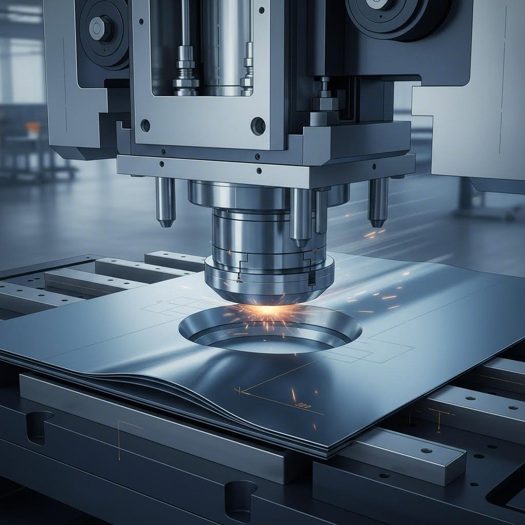
A compound die performs multiple cutting operations - specifically blanking and piercing - simultaneously in a single press stroke at one station. All features are cut relative to the same reference point in one operation, eliminating cumulative positioning errors.
This definition matters because it addresses a common misconception. Many assume compound dies are simply "complex dies" with intricate features. In reality, the term "compound" refers specifically to the simultaneous execution of multiple cutting processes - not complexity. A compound die can produce relatively simple parts, but it does so with exceptional precision because everything happens at once.
What Makes Compound Dies Unique in Metal Stamping
Imagine stamping a washer with both an inner hole and an outer edge. Using separate operations, you would first punch the center hole, then blank the outer diameter - or vice versa. Each operation introduces potential misalignment. With compound die stamping, both cuts occur in the same instant, at the same station, referencing the same datum point.
According to The Fabricator, stamping a part's ID and OD simultaneously eliminates distortion and enhances concentricity - qualities that are critical for washers and shims used in aerospace, medical, and energy applications. This single-station approach is what distinguishes compound tooling from progressive tooling, where material moves through multiple stations for sequential operations.
The Single-Stroke Simultaneous Cutting Concept
The engineering significance of this principle cannot be overstated. When all piercing, shearing, and blanking occur in one press stroke, you eliminate:
- Cumulative tolerance stack-up from multiple setups
- Registration errors between operations
- Material movement that causes dimensional variation
- Time lost to die changes or station transfers
For manufacturers seeking precision flat parts with multiple features - think gaskets, electrical laminations, or precision shims - this working principle directly translates to superior part quality. The material changes at the same station and at the same time, resulting in very high positioning accuracy and reduced cumulative tolerance.
So when your parts require tight concentricity between inner and outer features, or when flatness is non-negotiable, understanding this fundamental principle helps you specify the right tooling approach from the start.

Anatomy of a Compound Die System
Now that you understand why simultaneous cutting matters, let's explore what actually makes it possible. A compound tool relies on a precise arrangement of components working in perfect coordination. Unlike conventional die setups, this system flips the traditional configuration upside down - quite literally.
Core Components of a Compound Die Assembly
Every compound die assembly contains several critical elements, each serving a specific function during the cutting operation. Understanding these components helps you troubleshoot quality issues and communicate effectively with your tooling partners.
Here's a breakdown of the essential terminology you'll encounter when working with these types of dies:
- Knockout Pins: These components serve dual roles within the die cavity. According to Misumi, a knockout acts as both a stripper for the hole punching punch and an ejector for the finished product trapped inside the die. The knockout surface typically projects 0.5 mm to 1.0 mm beyond the die surface - contrary to the common assumption that it sits flush.
- Kicker Pins: Positioned within the knockout, these small pins prevent the blanked material from adhering to the knockout surface. When cutting oil coats the material, it can stick to the knockout and cause double-punching accidents that damage the die. The kicker pin projection is typically 0.5 mm to 1.0 mm.
- Pilots: These guide pins ensure precise material alignment before each stroke. They engage with previously pierced holes or sheet edges to position the strip accurately, maintaining consistent feature-to-feature relationships.
- Die Clearance: The gap between the punch and die cutting edges directly affects cut quality, tool life, and dimensional accuracy. As noted by The Fabricator, clearances can range from 0.5% up to 25% of metal thickness per side, depending on material hardness and punch geometry.
- Shear Angle: An angled cutting edge on the punch or die that reduces the instantaneous cutting force by distributing it across the stroke. This decreases press shock and extends tool life.
The Inverted Die Arrangement Explained
What truly distinguishes compound dies from other types of dies is their inverted placement structure. In conventional blanking setups, the punch descends from above while the die remains stationary below. Compound dies flip this arrangement.
In a compound die configuration:
- The blanking die mounts on the upper die shoe (moves with the press slide)
- The blanking punch sits on the lower die shoe (fixed to the bolster plate)
- The knockout assembles inside the upper die and connects to the press mechanism
Why does this inversion matter? According to Accushape Die Cutting, this arrangement serves as a countermeasure against product bending during blanking. The blanked product enters the die from below, and the knockout - synchronized with the blanking process - discharges the finished part. Because the material is pressed down by the knockout during cutting, it reduces the likelihood of bending or warping.
Implementing springs behind the knockout amplifies this effect. The springs provide controlled, consistent pressure against the material throughout the stroke, enabling efficient product ejection while maintaining flatness.
There's also a critical design consideration for the knockout itself. Making the knockout shape identical to the die cavity causes problems. Metal shreds generated during punching can accumulate in the gap between the knockout and die, leading to fusing or rough movement. Smart die designers provide escapes - small reliefs using radius or chamfer features - in detailed shape portions and corners to prevent debris buildup.
Understanding these components and their interactions is essential, but knowing how they move through a complete press cycle reveals even more about achieving consistent part quality.
Press Stroke Sequence and Force Dynamics
Imagine watching a compound die in slow motion. What appears instantaneous actually unfolds through a carefully orchestrated sequence of mechanical events. Each phase of the press stroke plays a distinct role in transforming flat sheet metal into a precision part. Understanding this sequence helps you diagnose quality issues and optimize your stamping operations.
The Five Phases of Compound Die Press Stroke
When the press activates, the upper die shoe begins its descent. What happens next determines whether you get a perfect part or scrap. Here's the complete cycle broken down into its essential phases:
- Approach Phase: The upper die shoe descends toward the sheet metal positioned on the lower die assembly. During this phase, pilots engage with the strip material, ensuring precise alignment before any cutting begins. The knockout, suspended within the upper die, remains ready to contact the material. Press speed during approach is typically faster than during cutting to maximize productivity.
- Contact Phase: Initial engagement occurs as the blanking die edge meets the sheet metal surface. At this moment, the knockout presses firmly against the material from above, sandwiching it between the knockout face and the lower blanking punch. This clamping action is critical - it prevents material movement and minimizes distortion during the cutting operation. Simultaneously, the piercing punches contact the material at their designated locations.
- Penetration Phase: Shearing begins as the die edges force into the material. This is where the real work happens. The metal doesn't simply slice apart - it undergoes a complex deformation process. First, plastic deformation occurs as the material compresses and begins to flow around the punch edges. As force increases, the metal's yield strength is exceeded, and shear fractures initiate from both the punch and die cutting edges. During this phase, blanking and piercing operations progress simultaneously, with all cutting edges advancing into the material at the same rate.
- Breakthrough Phase: Complete separation occurs as the fracture zones from punch and die sides meet. The blanked part drops into the die cavity while pierced slugs fall through their respective openings. This phase generates peak cutting forces and produces the characteristic "snap" heard during stamping operations. The material fracture happens nearly instantaneously once critical stress levels are reached.
- Return Phase: The upper die retracts, pulling the blanking die away from the freshly cut part. As the press slide rises, the knockout pins actuate - either through spring pressure or mechanical actuation - pushing the finished part out of the die cavity. The part ejects cleanly, and the strip advances to position fresh material for the next cycle.
How Simultaneous Blanking and Piercing Occurs
Here's what makes compound die operation fundamentally different from the progressive die stamping process. In progressive metal stamping, material moves through sequential stations where individual operations occur one after another. Each station adds features independently. But in a compound die, everything happens at once - and this creates unique force dynamics.
When blanking and piercing forces combine, the total press tonnage requirement equals the sum of individual cutting forces. You can't simply calculate blanking tonnage and assume that's sufficient. Consider a washer with a 50mm outer diameter and 25mm inner hole. The blanking force shears the outer perimeter while piercing force simultaneously cuts the inner circumference. Your press must handle both loads occurring at the exact same instant.
The tonnage calculation follows a straightforward formula: multiply the cut perimeter length by the material thickness and shear strength. For simultaneous operations, add the perimeters together:
- Outer blank perimeter: 157mm (50mm diameter x 3.14)
- Inner pierce perimeter: 78.5mm (25mm diameter x 3.14)
- Total cutting length: 235.5mm
This combined perimeter then factors into your tonnage calculation. Failing to account for simultaneous forces results in undersized press selection, leading to incomplete cuts, excessive tool wear, and premature die failure.
There's another force consideration unique to compound dies. Because the knockout presses against the material during cutting, additional force transfers through the knockout mechanism. This clamping pressure - while essential for part flatness - adds to the total load your press must accommodate.
Material Behavior Under Shearing Forces
What actually happens to the metal during that penetration phase? Understanding the metallurgical aspects helps you predict edge quality and troubleshoot burr problems.
As the punch enters the material, three distinct zones form on the cut edge:
- Rollover Zone: The top surface of the material rounds over slightly as the punch initially contacts and depresses the sheet. This plastic deformation creates a smooth, radiused edge at the entry point.
- Shear Zone (Burnish Zone): Below the rollover, a smooth, shiny band appears where clean shearing occurred. This is the high-quality portion of the cut edge. Proper die clearance maximizes this zone.
- Fracture Zone: The lower portion shows a rough, granular appearance where the material tore apart rather than sheared cleanly. Fracture initiates when cracks propagating from punch and die edges meet.
Burrs form at the die-side edge when fracture doesn't occur cleanly. Excessive clearance, dull tooling, or improper material support all contribute to burr formation. In compound die operation, burr direction is predictable and consistent because all cutting occurs simultaneously with identical clearance relationships.
The ratio between shear zone and fracture zone depth depends heavily on die clearance. Tighter clearances produce more burnish but require higher forces and cause faster tool wear. Finding the optimal balance requires understanding how clearance percentages affect your specific material - a relationship we'll explore in detail next.
Die Clearance and Precision Factors
You've seen how the press stroke unfolds and how material behaves under shearing forces. But here's a question that separates good parts from rejected ones: how much gap should exist between your punch and die? This seemingly small detail - measured in thousandths of an inch - directly determines whether your compound die produces crisp edges or ragged failures.
Die Clearance Calculations for Optimal Cut Quality
Die clearance refers to the gap between the cutting edges of the punch and die, measured per side. Get this wrong, and you'll battle burrs, premature tool wear, and dimensional inconsistencies throughout your production run.
The old rule of thumb - 10% of material thickness per side for all cutting operations - doesn't hold up under scrutiny. According to The Fabricator, cutting clearances can range from negative values (where the punch is actually larger than the hole) to as much as 25% per side. The optimal choice depends on material properties, not a one-size-fits-all percentage.
Here's what happens at each extreme:
- Insufficient clearance: When the gap is too tight, the metal is forced into compression during cutting. Once the slug breaks free, the material - which has elastic properties - grips the punch sides and creates excessive friction. This friction generates heat that can soften tool steel and cause abrasive galling. You'll see secondary shearing on cut edges, increased stripping forces, and dramatically shortened punch life.
- Excessive clearance: Too much gap creates its own problems. Larger burrs form at the die-side edge. Rollover increases significantly, sometimes leading to tensile fractures in the rollover zone. Parts lose flatness. While cutting forces decrease, your edge quality suffers.
The sweet spot produces approximately 20% shear (burnish) and 80% fracture on the cut edge. This ratio indicates proper crack propagation from both punch and die edges meeting cleanly in the middle of the material thickness.
For steel materials, clearance recommendations follow these general guidelines based on tensile strength:
- Materials below 60,000 PSI tensile strength: 6-10% per side
- Materials between 60,000-150,000 PSI: 12-14% per side (increasing with strength)
- Materials exceeding 150,000 PSI: Reduce back to approximately 5% per side
Why does ultra-high-strength material need less clearance? These steels have minimal ductility - they fracture before significant deformation occurs. The lack of metal flow that normally happens during cutting means tighter clearances work better.
Material Thickness Impact on Compound Die Performance
Material type and thickness interact in ways that affect every aspect of your compound die operation. Don't assume all materials behave similarly just because they share the same thickness specification.
Consider this scenario from The Fabricator's research: piercing a 0.5-inch hole in 0.062-inch thick 304 stainless steel requires approximately 14% clearance per side. But change that hole to 0.062 inches in diameter - equal to the material thickness - and the optimal clearance jumps to 18% per side. The smaller hole creates greater compression during cutting, demanding more room for material flow.
The following table summarizes recommended clearances based on material type and strength levels:
| Material Type | Tensile Strength Range | Recommended Clearance (% per side) | Notes |
|---|---|---|---|
| Mild Steel | Below 270 MPa | 5-10% | Standard baseline; burr height increases with wear |
| HSLA Steel | 350-550 MPa | 10-12% | Higher strength requires slightly more clearance |
| Dual Phase (DP) Steel | 600-980 MPa | 13-17% | Martensite islands act as crack initiators; optimize for edge ductility |
| Complex Phase (CP) Steel | 800-1200 MPa | 14-16% | 15% clearance often optimal per AHSS Insights |
| Martensitic Steel | 1150-1400 MPa | 10-14% | Low ductility limits burr formation; watch for punch edge chipping |
| Aluminum Alloys | Varies | 8-12% | Soft, gummy, and abrasive; requires lubrication attention |
Research from AHSS Insights demonstrates the practical impact of these choices. Testing on CP1200 steel showed that increasing clearance from 10% to 15% significantly improved hole expansion performance. A 20% clearance performed better than 10% but not as well as 15% - proving that more isn't always better.
Why Compound Dies Achieve Superior Concentricity
Here's where the compound die working principle delivers its most significant advantage. In progressive die metal stamping or transfer stamping, the material moves between stations. Each transfer introduces potential misalignment. Even with precise pilots and careful strip control, cumulative positioning errors accumulate.
Compound dies eliminate this problem entirely. Since blanking and piercing occur simultaneously at one station, all features reference the same datum point at the same instant. There's no opportunity for the material to shift, no chance for registration error between operations.
This single-datum approach produces measurable results:
- Concentricity: Inner and outer features maintain tight positional relationships because they're cut from the same reference. For washers, gaskets, and electrical laminations, this means consistent ID-to-OD relationships across thousands of parts.
- Flatness: The knockout mechanism presses material firmly against the lower punch during cutting, preventing the cupping or dishing that occurs when blanking and piercing happen separately.
- Burr uniformity: All burrs form on the same side of the part with consistent direction - predictable and manageable during secondary operations.
What tolerance capabilities can you realistically expect? With properly maintained compound tooling, typical tolerances fall within ±0.001 to ±0.003 inches for feature-to-feature positioning. Concentricity between inner and outer diameters commonly achieves 0.002 inches TIR (Total Indicator Runout) or better. These capabilities exceed what progressive die and stamping approaches typically deliver for equivalent part geometries.
The precision inherent in this approach makes compound dies the preferred choice for applications where feature alignment is critical - but knowing when this approach makes sense for your specific application requires evaluating several additional factors.
Compound Dies Versus Progressive and Transfer Dies
So you understand how compound dies achieve their precision through simultaneous cutting at a single station. But how does this approach stack up against the alternatives? When should you choose progressive die stamping instead? What about transfer die stamping for larger components? Making the right selection requires understanding not just what each die type does, but why it works that way.
Working Principle Differences Across Die Types
Each die type operates on fundamentally different principles - and those differences directly affect what parts you can produce, at what volumes, and to what precision standards. Let's break down how each approach actually works.
Compound Dies: Single-Station Simultaneous Cutting
As we've established, compound dies perform all cutting operations in one press stroke at one station. The material enters, gets blanked and pierced simultaneously, and exits as a finished flat part. There's no material transfer, no station-to-station movement, and no opportunity for cumulative positioning errors.
According to Keats Manufacturing, compound die stamping is a high-speed process ideal for producing flat parts like washers and wheel blanks in medium to high volumes. The engineering logic is straightforward: fewer operations mean fewer variables, and fewer variables mean tighter control over concentricity and flatness.
Progressive Dies: Sequential Station Processing
Progressive die stamping takes a completely different approach. A continuous metal strip feeds through multiple stations, each performing a specific operation - cutting, bending, piercing, or forming. The workpiece stays attached to the carrier strip throughout the process and separates only at the final station.
This working principle enables something compound dies cannot achieve: complex geometries requiring multiple forming operations. Die-Matic notes that progressive stamping is perfect for high-speed production of complex parts at medium to high volumes because the continuous process minimizes handling and maximizes throughput.
However, here's the trade-off. Each station transfer introduces potential alignment variation. Even with precise pilots, the cumulative effect of multiple positioning events can affect feature-to-feature accuracy - something that matters significantly for parts requiring tight concentricity.
Transfer Dies: Discrete Part Handling
Transfer die stamping combines elements of both approaches but operates on a distinct principle. According to Worthy Hardware, this process separates the part from the metal strip at the beginning - not the end - and mechanically transfers it from station to station using automated fingers or mechanical arms.
Why would engineers choose this seemingly more complex approach? The answer lies in what it enables: deep drawing, large part handling, and operations that require the workpiece to be completely free from surrounding material. Transfer dies can incorporate punching, bending, drawing, and trimming in a single production cycle - operations impossible to perform while the part remains connected to a carrier strip.
Simple Dies: Single Operation Focus
At the opposite end of the complexity spectrum sit simple dies. These perform a single operation per stroke - one hole, one blank, one bend. While straightforward and inexpensive to produce, simple dies require multiple setups and part handling for anything beyond basic components. Each additional operation multiplies handling time and introduces potential positioning errors.
Comparative Analysis: Die Types at a Glance
The following table summarizes how these die types differ across key operational and performance characteristics:
| Characteristic | Compound Die | Progressive Die | Transfer Die | Simple Die |
|---|---|---|---|---|
| Operation Method | Single station; simultaneous blanking and piercing | Multiple stations; sequential operations on continuous strip | Multiple stations; discrete part transfer between operations | Single station; one operation per stroke |
| Part Handling | Part created and ejected in one stroke | Automatic strip feed; part attached until final station | Mechanical fingers or arms transfer free blanks | Manual or automated loading/unloading each cycle |
| Typical Part Complexity | Flat parts with blanking and piercing only; no forming | Simple to complex; can include bending and forming | Complex, large, or deep-drawn parts with intricate features | Single-feature parts or one step in multi-die sequence |
| Production Volume Suitability | Medium to high volumes | High volumes; most cost-effective at scale | Short to long runs; versatile across volumes | Low volumes or prototyping |
| Precision Characteristics | Superior concentricity; tight feature-to-feature tolerance; excellent flatness | Good tolerances; potential cumulative error from station transfers | Good precision; flexibility for complex shapes | High precision per operation; cumulative error across multiple setups |
| Tooling Cost | Lower than progressive; simpler construction | Higher initial investment; cost-effective at volume | Higher setup complexity; suitable for specialized applications | Lowest initial cost per die |
Choosing the Right Die Type for Your Application
Sounds complex? Let's simplify the decision. The right choice depends on three primary factors: part geometry, precision requirements, and production volume.
When Compound Dies Make Sense
Choose this approach when your application meets these criteria:
- Flat parts requiring only blanking and piercing operations
- Tight concentricity requirements between inner and outer features
- Critical flatness specifications that can't tolerate station-transfer distortion
- Medium production volumes where progressive die tooling costs aren't justified
- Applications like washers, gaskets, electrical laminations, and precision shims
The engineering logic is compelling. As Keats Manufacturing points out, one stroke produces flatter parts, and the single-die approach facilitates high repeatability. When your quality metrics center on concentricity and flatness, compound dies deliver.
When Progressive Dies Outperform
Progressive die stamping becomes the preferred choice under different circumstances:
- High-volume production where per-part cost must be minimized
- Parts requiring bending, forming, or other operations beyond cutting
- Complex geometries with multiple features that can be added sequentially
- Small parts where strip attachment provides better handling than discrete blanks
According to Die-Matic, progressive stamping offers production speed, fast cycle times, reduced labor costs, and lower per-unit costs. The continuous process eliminates part handling between operations, making it exceptionally efficient for suitable applications.
When Transfer Dies Are Essential
Transfer die stamping isn't just an alternative - for certain applications, it's the only viable option:
- Large parts that won't fit within strip-feeding constraints
- Deep-drawn components where the material must flow freely without strip attachment
- Parts requiring operations on all sides or complex orientation changes
- Designs incorporating threading, ribs, knurls, or similar intricate features
Worthy Hardware emphasizes that transfer die stamping allows more flexibility in part handling and orientation, making it suitable for intricate designs and shapes that simply cannot be produced any other way.
The Engineering Logic Behind Each Approach
Why do these different working principles exist? Each evolved to solve specific manufacturing challenges.
Compound dies emerged from the need for precision in flat parts. By eliminating material movement between operations, engineers could guarantee feature alignment. The trade-off - limitation to cutting-only operations - was acceptable because many critical applications (think electrical laminations or precision gaskets) require exactly that.
Progressive dies developed to address high-volume production of increasingly complex parts. The genius of the continuous strip approach lies in its efficiency: the material feeds automatically, operations occur at line speed, and only the final separation requires part handling. For automotive brackets, electronic connectors, and similar high-volume components, this approach remains unmatched.
Transfer dies filled the gap where neither compound nor progressive approaches work. When parts are too large for strip feeding, require deep drawing, or need operations incompatible with strip attachment, transfer stamping provides the solution. The mechanical transfer mechanism adds complexity but enables manufacturing flexibility impossible to achieve otherwise.
Understanding these fundamental differences helps you make informed tooling decisions. But once you've identified compound dies as the right approach for your flat, high-precision parts, the next question becomes: what quality outcomes can you realistically expect from this single-station operation?
Part Quality Outcomes from Compound Die Operation
You've seen how compound dies compare to progressive and transfer alternatives. But here's what really matters when parts reach your inspection table: measurable quality outcomes. The single-station simultaneous cutting approach doesn't just sound good in theory - it delivers specific, quantifiable advantages that directly affect whether your parts pass or fail quality checks.
Quality Advantages of Single-Station Compound Die Operation
When you choose compound die stamping, you're not just selecting a manufacturing method - you're selecting a quality profile. According to Progressive Die and Stamping, using a single station improves mechanical accuracy and makes it easier to maintain part flatness and achieve close dimensional tolerances. But what does this mean in practical terms?
Consider what happens in multi-station processes. Each time material transfers between stations, positioning variables accumulate. Pilots must re-engage. Strip tension fluctuates. Thermal expansion affects alignment. Even with precision tooling, these micro-variations stack up across operations.
Compound dies eliminate every one of these error sources. The material enters the die, all cutting occurs simultaneously, and the finished part ejects - all in a single stroke at a single station. There's simply no opportunity for the part to shift, rotate, or misalign between operations.
Here are the specific quality metrics that compound die operation directly influences:
- Concentricity: Inner and outer features maintain positional accuracy within 0.002 inches TIR or better because they're cut from the same datum point in the same instant
- Flatness: Parts remain flat because the knockout mechanism applies consistent pressure throughout cutting, preventing the cupping or dishing common in sequential operations
- Burr consistency: All burrs form on the same side with identical direction, making secondary finishing operations predictable and efficient
- Dimensional stability: Feature-to-feature tolerances of ±0.001 to ±0.003 inches are routinely achievable with properly maintained tooling
- Edge quality uniformity: Every cut edge exhibits the same shear-to-fracture ratio because identical clearance relationships exist across all cutting operations
- Repeatability: Part-to-part consistency improves because fewer process variables exist to cause drift over production runs
How Compound Dies Achieve Superior Dimensional Accuracy
The engineering logic is straightforward: since the part never moves between operations, there is zero opportunity for misalignment or registration error. But let's examine exactly how this translates to dimensional accuracy.
In progressive metal stamping, imagine producing a simple washer. First, the strip advances to a piercing station where the center hole is punched. Then the strip moves to a blanking station where the outer diameter is cut. Even with precision pilots re-engaging the previously pierced hole, minor variations occur. Strip feed accuracy, pilot-hole clearance, and material springback all contribute to positional uncertainty between the inner and outer features.
Now consider the same washer produced in a compound die. The piercing punch and blanking die engage the material simultaneously. Both cutting edges reference the identical position at the identical moment. The result? Perfect concentricity between inner diameter and outer diameter - not because of careful alignment between stations, but because no alignment between stations is required.
As industry experts note, by creating parts with one die, manufacturers ensure consistency and accuracy while achieving flatness and good dimensional stability. This isn't marketing language - it's a direct consequence of the physics involved.
Critical Applications Where These Quality Characteristics Matter
Certain applications demand the quality profile that only compound die operation delivers. When you're manufacturing components where feature alignment directly affects function, this precision stamping process becomes essential rather than optional.
Washers and Shims: These seemingly simple components require tight concentricity between inner bore and outer diameter. A washer with eccentric features won't seat properly, creating uneven load distribution that leads to fastener loosening or premature failure. Compound dies produce washers where ID-to-OD concentricity is guaranteed by the manufacturing principle itself.
Gaskets: Sealing components demand consistent geometry across the entire part. Any variation in the relationship between bolt holes and sealing surfaces creates leak paths. Because compound dies cut all features simultaneously, the positional relationships remain consistent from the first part to the ten-thousandth.
Electrical Laminations: Motor and transformer laminations require precise geometry to minimize energy losses and ensure proper magnetic flux paths. The flatness advantage of compound die operation is particularly critical here - even slight warping affects stack assembly and electromagnetic performance. According to Metalcraft Industries, precision metal stamping achieves tolerances of 0.001 to 0.002 inches for intricate designs with zero room for error.
Precision Flat Components: Any application requiring multiple features to maintain tight positional tolerances benefits from single-station operation. Instrument components, optical mounts, and precision hardware all fall into this category.
The compound die quality advantage isn't about producing "better" parts in some abstract sense - it's about producing parts where specific quality metrics are critical to function. When concentricity, flatness, and dimensional accuracy determine whether your assembly works or fails, the single-station simultaneous cutting principle delivers results that sequential processing simply cannot match.
Understanding these quality outcomes helps you specify the right tooling approach. But the next step is developing a practical framework for determining when compound dies are truly the optimal choice for your specific application requirements.
Decision Framework for Compound Die Applications
You now understand the quality advantages compound dies deliver. But here's the practical question every manufacturing engineer faces: is this approach right for your specific application? Making the wrong die tooling decision wastes development time, inflates costs, and potentially compromises part quality. Let's build a clear decision framework that helps you determine when compound die selection makes sense - and when it doesn't.
When to Specify Compound Die Tooling
Not every stamped part benefits from the compound die working principle. This approach excels in specific scenarios where its unique characteristics align with your requirements. Before committing to tooling development, evaluate your application against these criteria.
Ideal Scenarios for Compound Die Selection:
- Flat parts requiring only blanking and piercing: Compound dies perform cutting operations exclusively. If your part requires bending, forming, drawing, or other shape-changing operations, you'll need progressive or transfer dies instead.
- Tight concentricity requirements: When inner and outer features must maintain precise positional relationships - think washers, gaskets, or laminations - the simultaneous cutting principle eliminates alignment variables that plague multi-station processes.
- Critical flatness specifications: The knockout mechanism applies consistent pressure during cutting, preventing the cupping or dishing that occurs when blanking and piercing happen separately. Parts requiring flatness within 0.002 inches or better benefit significantly.
- Medium production volumes: According to industry sources, compound stamping becomes cost-effective for quantities ranging from 10,000 to 100,000 pieces, where the die cost can be offset by reduced labor and equipment usage.
- Simple to moderately complex geometries: Multiple holes, internal cutouts, and irregular outer profiles are all achievable - as long as no forming is required.
Here's a quick self-assessment checklist to guide your metal stamping decision:
| Selection Criteria | Yes | No | Implication |
|---|---|---|---|
| Is the part completely flat (no bends or forms)? | ✓ Compound die candidate | Consider progressive or transfer die | Compound dies perform cutting only |
| Does the part require blanking and piercing operations? | ✓ Core compound die capability | Evaluate if single operation die suffices | Simultaneous operations are the advantage |
| Is concentricity between features critical (±0.002" or tighter)? | ✓ Strong compound die advantage | Progressive die may be acceptable | Single-station eliminates cumulative error |
| Is flatness a critical quality metric? | ✓ Compound die preferred | Other die types may work | Knockout pressure maintains flatness |
| Is production volume between 10,000-100,000 parts? | ✓ Optimal cost-benefit range | Evaluate alternatives for lower/higher volumes | Die cost amortizes effectively in this range |
Application Criteria for Compound Die Selection
Beyond the basic checklist, several application-specific factors influence whether compound tooling is your best choice. Understanding these die tooling requirements helps you make informed decisions before committing resources.
Limitations You Must Consider:
- No forming capability: Compound dies cannot bend, draw, emboss, or otherwise form material. If your part requires any shape change beyond flat cutting, you'll need a different approach - or a secondary operation.
- Geometry constraints: While compound dies handle moderate complexity well, extremely intricate parts with dozens of features may prove impractical. The die becomes difficult to manufacture and maintain.
- Higher per-stroke forces: Because all cutting operations occur simultaneously, the combined tonnage requirement exceeds what a progressive die might need at any single station. Your press must handle the total load in one instant.
- Part ejection considerations: The finished part must clear the die cavity reliably. Very large parts or unusual geometries may complicate ejection and require specialized knockout arrangements.
Press Requirements and Tonnage Calculations
Selecting the right press for compound die operation requires careful force analysis. Unlike progressive stamping - where forces distribute across multiple stations - compound dies concentrate all cutting forces into a single stroke.
The tonnage calculation follows a straightforward formula:
Tonnage = (Total Cut Perimeter × Material Thickness × Shear Strength) ÷ 2000
For compound dies, "total cut perimeter" includes every cutting edge engaged simultaneously - outer blanking perimeter plus all piercing perimeters. According to industry guidelines, typical material shear strengths range from 30,000 PSI for aluminum to 80,000 PSI for stainless steel.
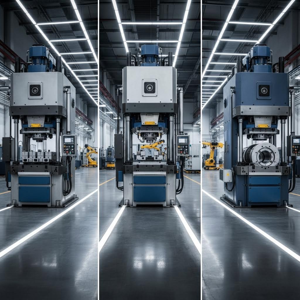
Press Type Considerations:
- Open Back Inclinable (OBI) presses: Well-suited for compound die work. According to stamping references, running an OBI press in the inclined position with air blow-off assists in part removal from the die cavity.
- Straight-side presses: Provide superior rigidity for higher tonnage requirements and tighter tolerance work.
- Mechanical vs. hydraulic: Mechanical presses offer speed advantages for production runs; hydraulic presses provide force control benefits for thick or difficult materials.
Don't forget to include stripping force in your calculations. The force required to strip material from punches typically adds 5-10% to your cutting tonnage requirement, though this can reach 25% in challenging applications.
With your application criteria evaluated and press requirements understood, the final step is connecting these engineering principles to real-world implementation - working with tooling partners who can translate your specifications into production-ready die solutions.

Precision Tooling Partners and Manufacturing Excellence
You've evaluated your application criteria, calculated tonnage requirements, and confirmed that compound die tooling is the right approach. Now comes the critical step that determines whether your precision stamping dies deliver consistent, high-quality parts - or become an expensive source of production headaches. The gap between theoretical die design and reliable manufacturing performance depends entirely on implementation.
Implementing Compound Die Solutions in Production
Moving from design concept to production-ready tooling involves more than just machining die components to specification. Modern precision stamping die development integrates simulation, validation, and iterative refinement long before metal ever cuts metal.
Consider what typically goes wrong without proper implementation:
- Die clearances that work in theory but cause premature wear in practice
- Knockout mechanisms that jam under production speeds
- Material flow patterns that create unexpected burrs or edge defects
- Tonnage calculations that underestimate real-world force requirements
Each of these failures traces back to the same root cause: insufficient validation before production commitment. According to Keysight's research on stamping simulation, tool design is crucial for die efficiency and longevity, with materials like tool steel or carbide chosen for durability based on the specific metals being processed. But material selection alone doesn't guarantee success - the complete system must work together under actual operating conditions.
The Role of CAE Simulation in Die Development
Computer-aided engineering has transformed how stamping die manufacturers approach precision tooling. Rather than building physical prototypes and iterating through trial-and-error, modern die engineering services use simulation to predict:
- Material flow behavior during the cutting stroke
- Stress distribution across punch and die components
- Potential failure modes before they occur in production
- Optimal clearance settings for specific material grades
- Force requirements and knockout timing parameters
This simulation-first approach reduces development cycles dramatically. Instead of discovering problems during production trials - when tooling modifications are expensive and time-consuming - issues surface during the virtual testing phase. The result? Dies that perform correctly from their first production stroke.
As noted in industry trend analysis, advanced simulation software allows designers to explore material options and optimize designs before production, ultimately leading to cost savings and better overall product quality. This capability has become essential for automotive stamping tooling, where first-pass success rates directly impact program timelines.
Engineering Support for Precision Stamping Die Development
Beyond simulation capabilities, successful compound die implementation requires engineering partners who understand both the theoretical working principles and the practical constraints of high-volume manufacturing. This combination proves surprisingly rare.
Many tooling suppliers excel at machining precision components but lack deep expertise in stamping process physics. Others understand theory but struggle to translate that knowledge into robust production tooling. The manufacturers who consistently deliver precision stamping dies that work from day one combine both capabilities.
What to Look for in a Die Engineering Partner:
- Quality system certification: IATF 16949 certification indicates automotive-grade quality management systems - the most demanding standard in precision manufacturing
- Simulation capability: CAE integration that validates designs before cutting steel
- Rapid prototyping: The ability to move quickly from concept to physical tooling when development timelines are compressed
- First-pass success metrics: Track records that demonstrate consistent die performance without extensive tryout iterations
- Material expertise: Understanding of how different steel grades, aluminum alloys, and advanced high-strength materials behave under compound die cutting conditions
The global stamping market is projected to reach approximately $372.6 billion, with increasing demand for high-precision parts across automotive, aerospace, and energy sectors. This growth is driving manufacturers toward tooling partners who can deliver both precision and speed.
A Case for Comprehensive Die Engineering Capability
When evaluating stamping die manufacturer options for compound die development, consider how their capabilities align with your specific requirements. Some manufacturers specialize in high-volume commodity tooling; others focus on complex progressive dies. For precision flat parts requiring the concentricity and flatness advantages of compound die operation, you need partners whose expertise matches your application.
Shaoyi represents one strong option for manufacturers seeking precision compound die tooling tailored to OEM standards. Their approach combines several capabilities relevant to compound die success:
- IATF 16949 certification: Evidence of automotive-grade quality systems that ensure consistent die performance
- Advanced CAE simulation: Virtual validation that identifies potential issues before physical tooling is produced, supporting defect-free results
- Rapid prototyping: Development timelines as fast as 5 days when program schedules demand quick turnaround
- 93% first-pass approval rate: A metric that demonstrates engineering expertise translating into production-ready tooling without extensive iteration
For manufacturers exploring comprehensive mold design and fabrication capabilities, their automotive stamping dies resource provides detailed information on available die engineering services.
Connecting Principles to Production Success
The compound die working principle delivers exceptional concentricity, flatness, and dimensional accuracy - but only when implemented correctly. The gap between theoretical advantage and practical performance depends on:
- Accurate translation of application requirements into die specifications
- Simulation-validated designs that anticipate real-world behavior
- Precision manufacturing of die components to specified tolerances
- Proper press selection and setup for the simultaneous cutting forces involved
- Ongoing maintenance practices that preserve die performance over production life
When these elements align, compound dies deliver the quality outcomes that make them the preferred choice for precision flat parts. When any element falls short, the advantages of single-station simultaneous cutting remain theoretical rather than realized.
Your parts don't fail because compound dies are inherently problematic. They fail when the implementation doesn't match the principle. Working with tooling partners who understand both the engineering fundamentals and practical manufacturing realities transforms compound die tooling from a specification on paper into consistent production performance - part after part, stroke after stroke.
Frequently Asked Questions About Compound Die Working Principle
1. What is the difference between a compound die and a progressive die?
Compound dies perform multiple cutting operations (blanking and piercing) simultaneously in a single stroke at one station, producing finished parts with superior concentricity. Progressive dies move material through multiple stations sequentially, performing one operation at each station. While progressive dies handle complex parts with bending and forming, compound dies excel at flat parts requiring tight tolerances between features because all cuts reference the same datum point instantly.
2. What is the difference between combination and compound die?
Compound dies are limited to cutting operations only - specifically blanking and piercing performed simultaneously. Combination dies can perform both cutting and forming operations (like bending or drawing) in the same stroke. If your part requires any shape change beyond flat cutting, you need a combination die or alternative tooling approach rather than a compound die.
3. What are the main advantages of compound die stamping?
Compound die stamping delivers three key advantages: superior concentricity between inner and outer features (typically 0.002 inches TIR or better), excellent part flatness due to knockout pressure during cutting, and high dimensional accuracy (±0.001 to ±0.003 inches). These benefits result from eliminating material movement between operations - all features are cut from the same reference point in a single stroke.
4. What types of parts are best suited for compound die manufacturing?
Compound dies are ideal for flat parts requiring blanking and piercing only, including washers, gaskets, electrical laminations, shims, and precision flat components. Parts requiring tight concentricity between holes and outer edges, critical flatness specifications, and medium production volumes (10,000-100,000 pieces) benefit most from this tooling approach.
5. How do you calculate press tonnage for compound die operations?
Calculate compound die tonnage by multiplying total cut perimeter (outer blank plus all piercing perimeters) by material thickness and shear strength, then dividing by 2000. Since all cutting forces occur simultaneously, the press must handle the combined load in one stroke. Add 5-10% for stripping force. This differs from progressive dies where forces distribute across multiple stations.