 Small batches, high standards. Our rapid prototyping service makes validation faster and easier —

Troubleshooting Progressive Die Misfeeds: The 4 Root Causes

TL;DR
Immediate Diagnostic Priority: Before adjusting guide rails or sensors, verify your pilot release timing. Industry data suggests that over 90% of unexplained progressive die misfeeds stem from improper feed release calibration.
Troubleshooting should follow this hierarchy: First, inch the press to ensure feed rolls open exactly when pilot pins enter the strip. Second, verify the feed line height and die alignment to prevent binding. Third, check for material issues like coil camber (sickle bend). Finally, inspect for physical obstructions like slug pulling or sticky lubrication. Addressing the pilot release timing resolves the vast majority of positioning errors.
Diagnostic Phase 1: The Criticality of Pilot Release Timing
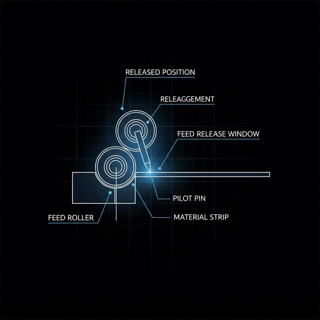
In the hierarchy of stamping failures, the pilot release (or feed release) mechanism is the most frequent culprit. The mechanical logic is simple but unforgiving: the coil feeder moves the material forward by one progression, but the die’s pilot pins are responsible for the final micro-alignment. For this handover to occur without error, the feed rollers must unclamp the strip at the exact moment the pilot pins engage the material.
If the feed rolls open too early, the weight of the take-up loop (the slack material between the feeder and the coil) creates a backward tension, pulling the strip out of position before the pilots can secure it. This often manifests as inconsistent pitch or short feeds. Conversely, if the rollers open too late, the strip is still clamped rigidly while the tapered pilot pins attempt to force it into alignment. This fight between the feeder’s brake and the pilot’s location force results in buckled strips, elongated pilot holes, and broken pilot tips.
Procedure to Set the Release Point:
- Inch the press downward slowly until the bullet-nosed tips of the pilot pins just begin to enter the strip material.
- At this exact point, the feed rollers should release (open).
- Continue inching the press through the bottom of the stroke (180 degrees) and up the return stroke. The rollers must remain open this entire time to allow the strip to float freely as the die closes and opens.
- The rollers should only clamp the strip again once the pilots have fully withdrawn and the strip has returned to the feed line height.
This window of "free float" is non-negotiable. For dies with significant lift (such as those producing deep-drawn parts), the timing must account for the vertical travel of the lifter bars. If the rollers clamp while the strip is still elevated, the material will be pulled backward as it settles down to the feed line, guaranteeing a misfeed on the next stroke.
Diagnostic Phase 2: Feed Line Height and Die Alignment
Once timing is verified, the next variable to isolate is the geometry of the feed. A fundamental rule of die setting is that the material must enter the tool parallel to the die face. If the feed line height is set incorrectly—even by a fraction of an inch—it introduces an angular vector to the push force. Instead of sliding smoothly, the strip is driven downward or upward into the guides, causing friction, buckling, and eventual binding.
Feed Table Alignment Checklist:
- Vertical Height: The bottom of the strip as it leaves the feeder must effectively match the height of the die’s feed level (top of the lifters or wear plates).
- Parallelism: The feeder’s centerline must be perfectly parallel to the die’s centerline. Misalignment creates side-loading on the pilot pins, causing them to bend or wear prematurely.
- Die Keying: Do not rely on clamps alone to align the die. Use precision-machined die keys in the bolster plate slots to ensure the tool is mathematically parallel to the press bed and feeder.
For applications involving deep drawing, the challenge increases. As the strip is lifted off the die face to advance, the angle between the fixed feeder and the elevated strip changes. If the feeder is too close to the die, this angle becomes steep, kinking the material. Increasing the distance between the feeder and the die—or employing a height-adjustable feed table—can reduce this angular stress and prevent the strip from binding in the lifters.
Diagnostic Phase 3: Material & Strip Issues (Camber & Carrier)
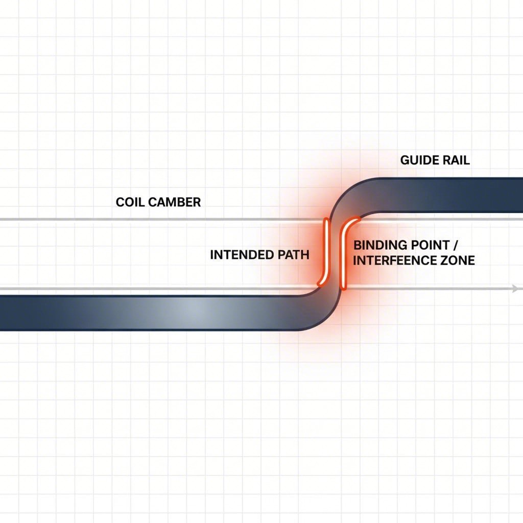
Sometimes the tool and feeder are perfect, but the raw material is non-conforming. Coil camber, often called "sickle bend," refers to curvature along the edge of the coil stock caused by the slitting process. When a cambered strip is forced through rigid, parallel guide rails, it acts like a wedge. Eventually, the curvature forces the strip to bind against one rail, preventing it from reaching the forward stop.
A common error is setting the stock guides too tightly. Operators often tighten guides to "force" the strip straight. However, guide rails are only intended to bring the strip within the capture range of the pilot pins. They cannot correct camber. If you observe binding, loosen the entry guides slightly to allow the pilots to do their job of final registration. If the camber is severe (outside of ASTM specifications), the root cause lies with the straightener settings or the slitting vendor, not the die.
Carrier Strip Integrity: In progressive dies, the carrier web is the skeleton that transports the parts. If the carrier is designed too weak or narrow, the thrust of the feeder can cause it to buckle, especially if the strip encounters resistance. Inspect the carrier for crimping or accordion-like damage, which indicates the feed force exceeds the column strength of the material strip.
Diagnostic Phase 4: Obstructions and Mechanical Interferences
The final category of misfeeds involves physical blockages within the tool. Slug pulling is a notorious offender where a punched scrap slug adheres to the punch face and is drawn back up out of the die button. If this slug falls onto the strip surface, it prevents the material from advancing or creates a double-metal crash.
Common Obstruction Drivers:
- Magnetism: Residual magnetism in the tool steel can hold slugs or chips. Demagnetizing the die set is a standard maintenance step.
- Lubricant Viscosity: Oil that is too tacky (high viscosity) can create a suction effect, causing slugs to stick to the punch. Conversely, oil that is too thin may not protect the pilot pins from galling.
- Burrs: A large burr on the carrier strip can catch on a lifter or guide rail, halting the feed instantaneously.
When high-volume production faces chronic issues with material consistency or tooling wear, the solution often requires revisiting the manufacturing strategy itself. For automotive components requiring IATF 16949 compliance, partnering with a specialist like Shaoyi Metal Technology can bridge the gap between prototyping and mass production. Their capability to handle press tonnages up to 600 tons and manage precision control arms or subframes ensures that foundational process variables—like material handling and die maintenance—are stabilized before they become downtime events.
Ultimately, a misfeed is a symptom, not the disease. By methodically checking timing, alignment, material straightness, and physical clearance, you can identify the mechanical reality preventing the strip from moving forward.
FAQ: Progressive Die Troubleshooting
1. How do I know if my pilot release is late?
If the pilot release is set too late, you will often see elongated pilot holes in the strip. This happens because the pilot pin is dragging against the hole edge while the feeder is still clamping the material. You may also hear a distinct "snapping" sound as the strip is forced into place, or notice premature wear on the pilot tips.
2. What is the ideal feed line height?
The feed line height should be set so that the material enters the die perfectly horizontal, matching the level of the lifters or the die face (depending on the tool design). A good rule of thumb is to ensure the strip does not touch the bottom or top of the guide rails as it enters. It should "float" in the center of the vertical clearance.
3. Can increasing pilot pressure fix a misfeed?
No. Increasing the spring pressure on the pilots or lifters rarely fixes a misfeed and often masks the root cause. If the strip isn't locating, the issue is almost always timing (release) or geometric (binding). increasing pressure will likely just cause the pilots to punch through the strip or buckle the carrier web.