 Small batches, high standards. Our rapid prototyping service makes validation faster and easier —

Calculating Press Tonnage for Automotive Parts: The Engineering Guide

TL;DR
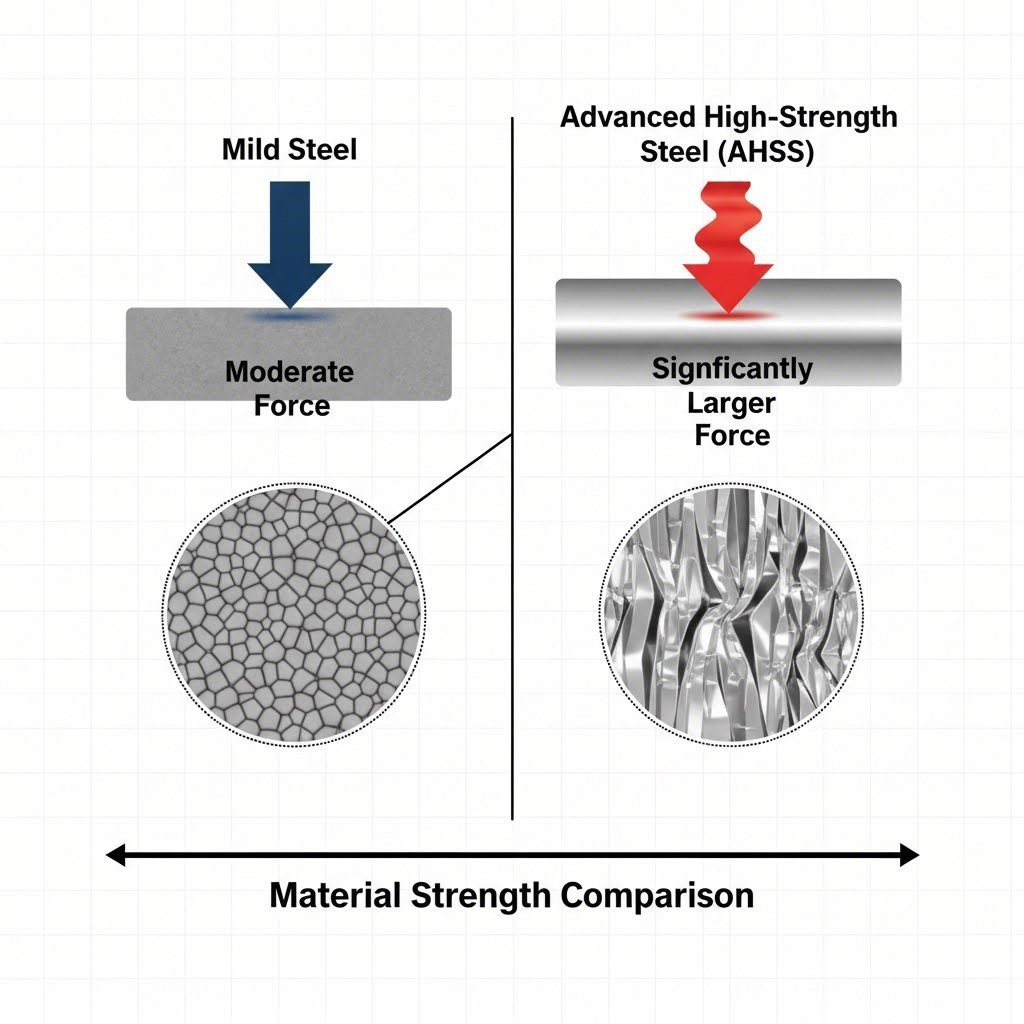
Accurately calculating press tonnage for automotive parts requires distinct approaches for metal stamping and injection molding, with a critical warning for modern materials. For metal stamping, the baseline formula is Tonnage = Perimeter × Thickness × Shear Strength. However, standard calculations fail dangerously with Advanced High-Strength Steel (AHSS), where higher tensile strengths and work hardening can multiply required force by factors of 3–5x compared to mild steel.
For injection molding applications, the primary formula is Clamp Force = Projected Area × Clamp Factor (typically 2–5 tons/in² depending on wall thickness). Engineering teams must verify not just peak tonnage, but also the press's energy capacity (flywheel energy) to prevent stalling during deep-draw operations. Always validate calculations with Finite Element Analysis (FEA) before finalizing die designs.
The AHSS Paradigm Shift: Why Old Formulas Fail
In the automotive sector, the transition from mild steel to Advanced High-Strength Steel (AHSS) has rendered 1980s "rule of thumb" calculations obsolete. While traditional rules (like length × thickness × constant) worked for generic brackets, they pose severe safety risks for modern automotive structural components like B-pillars or chassis reinforcements.
AHSS grades, such as Dual Phase (DP) and 3rd Generation steels, now regularly exceed tensile strengths of 1180 MPa. This introduces a "Multiplier Effect" where the force required to shear or form the material does not scale linearly. AHSS Guidelines warn that conventional predictions often underestimate the required tonnage, leading to press stalls or catastrophic frame damage.
Furthermore, engineers must account for Work Hardening. Unlike mild steel, which maintains relatively consistent behavior, AHSS strengthens significantly as it is deformed. A material starting at 980 MPa yield strength may rise by over 100 MPa during the forming process. Consequently, a press selected based solely on the material's initial properties will often lack the necessary energy curve to complete the stroke, even if its rated peak tonnage appears sufficient.
Part 1: Metal Stamping Tonnage Calculations
For structural automotive parts, accurate tonnage calculation begins with the physics of shear and tensile failure. The calculation differs depending on whether the operation is cutting (blanking/piercing) or forming (drawing/bending).
The Base Formula: Blanking and Piercing
The fundamental formula for calculating the force required to cut through sheet metal is:
T = L × t × Ss
- T = Tonnage (Force required)
- L = Total Length of the Cut (Perimeter)
- t = Material Thickness
- Ss = Shear Strength of the material
Crucial Material Adjustment: For standard mild steel, Shear Strength is often estimated as 80% of Tensile Strength. However, for high-strength automotive alloys, you must consult the mill's certification. Using a generic constant here is the most common cause of under-sizing presses.
Correcting for Stripping and Safety
The cutting force is only part of the equation. You must add Stripping Force—the force required to withdraw the punch from the material, which grips tightly due to springback. For AHSS, stripping force can reach 20% of the cutting force. Therefore, the total required tonnage ($T_{total}$) should generally be calculated as:
$T_{total} = T_{cutting} imes 1.20$ (safety and stripping factor)
Practical Application in Production
When moving from theoretical calculation to physical production, equipment capability becomes the limiting factor. For manufacturers bridging the gap from rapid prototyping to mass production, selecting a partner with diverse press capacities is vital. Companies like Shaoyi Metal Technology utilize presses up to 600 tons to accommodate the high-force requirements of automotive control arms and subframes, ensuring that theoretical calculations align with IATF 16949-certified execution.
Part 2: Injection Molding Clamp Tonnage
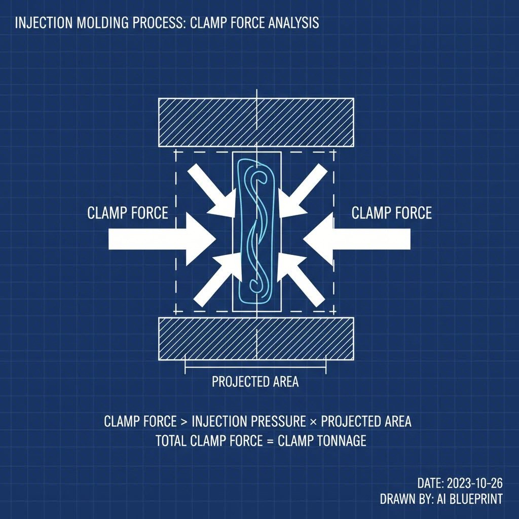
While metal stamping dominates the chassis discussion, a significant portion of "automotive parts" implies interior and aesthetic components produced via injection molding. Here, the critical metric is Clamp Tonnage—the force required to keep the mold closed against the injection pressure.
The Projected Area Formula
The industry-standard formula for estimating clamp force is:
F = A × CF
- F = Clamp Force (Tons)
- A = Total Projected Area (including runners)
- CF = Clamp Factor (Tons per square inch/cm)
Automotive Specifics: Thin Walls and High Flow
Standard consumer plastics might use a clamp factor of 2–3 tons per square inch. However, automotive parts like bumpers or thin-wall instrument panels typically require higher injection pressures to fill the cavity before the material freezes. RJG Inc. notes that for these demanding applications, the clamp factor should often be increased to 3–5 tons per square inch. Additionally, a safety margin of 10% should be added to prevent flash, ensuring the press operates within a stable window rather than at its absolute limit.
Advanced Sizing: Energy vs. Peak Tonnage
A common error in automotive press selection is confusing Tonnage Rating with Energy Capacity. A 500-ton press can only deliver 500 tons of force near the very bottom of the stroke (Bottom Dead Center). If your automotive part requires a deep draw (e.g., a 4-inch deep oil pan), the forming begins several inches above the bottom.
At this height, the press's mechanical advantage is lower, and the available tonnage is significantly "derated." More critically, deep drawing consumes a massive amount of energy from the flywheel. If the energy required to move the metal exceeds the flywheel's stored kinetic energy, the press will stall, regardless of its tonnage rating. The Fabricator highlights that ignoring the "Tonnage Curve" is a primary cause of motor burnout and clutch failure in automotive stamping.
The Danger of Reverse Tonnage
High-tensile blanking operations release tremendous energy instantly when the material fractures. This creates "Reverse Tonnage" (or snap-through), sending shockwaves back through the press structure. While standard presses tolerate reverse loads of roughly 10% of capacity, cutting AHSS can generate reverse loads exceeding 20%. This repeated shock fatigue cracks press frames and destroys sensitive electronics. Hydraulic dampers or specialized servo presses are often required to mitigate this risk.
The Role of Simulation (AutoForm/FEA)
Given the variables of work hardening, friction coefficients, and complex geometries, manual hand calculations must be viewed as estimates, not final specifications. Leading automotive suppliers now mandate the use of Finite Element Analysis (FEA) software, such as AutoForm, for final press selection.
Simulation provides insights that formulas miss, such as:
- Active Binder Forces: The variable force needed to hold the sheet in place during drawing.
- Local Hardening Maps: Visualizing exactly where the material yield strength spikes during forming.
- Friction Evolution: How lubricant breakdown affects tonnage requirements mid-stroke.
According to Stamping Simulation, verifying the process digitally prevents the exorbitant cost of "die crashes" during physical tryout. For quoting purposes, always use the upper bound of the simulation results to account for material batch variations.
Engineering Integrity in Tonnage Calculation
The margin for error in calculating press tonnage for automotive parts has vanished. The introduction of high-strength alloys means that under-sizing a press is no longer a minor efficiency issue—it is a catastrophic risk to machinery and safety. Engineers must move beyond static formulas to a dynamic understanding of material behavior, energy curves, and simulation data.
By rigorously distinguishing between peak load and energy capacity, and verifying results with FEA, manufacturers can protect their assets and ensure the delivery of defect-free components. In this high-stakes environment, precision is not just a goal; it is the only operational standard.
Frequently Asked Questions
1. What is the difference between hydraulic and mechanical press tonnage?
Hydraulic presses can deliver full rated tonnage at any point in the stroke, making them ideal for deep drawing where force is needed early. Mechanical presses can only deliver full tonnage near the bottom of the stroke (Bottom Dead Center) and are limited by flywheel energy at higher positions.
2. How does material thickness affect tonnage calculation?
Tonnage is directly proportional to material thickness in blanking operations. Doubling the thickness doubles the required force. However, in bending and forming, thickness increases force exponentially, often requiring adjustments to the die opening width to manage the load.
3. Why is a safety margin necessary for press tonnage?
A safety margin of 20% is recommended to account for material variations (like thicker batches from the mill), tool wear (dull punches require more force), and to prevent the press from operating at maximum capacity, which accelerates wear on the frame and drive system.