 Small batches, high standards. Our rapid prototyping service makes validation faster and easier —

Choosing Press Stroke for Stamping: Speed, Torque & Physics
TL;DR
Choosing the correct press stroke is a trade-off between productivity (SPM) and process feasibility. For blanking, punching, and high-speed operations, select the shortest possible stroke (typically 0.5 to 1.5 inches) to minimize impact velocity, extend tool life, and maximize strokes per minute. A shorter stroke reduces the distance the ram travels, allowing for faster cycle times without increasing the slide's velocity at the point of impact.
For deep drawing and complex forming, the stroke length is dictated by part clearance. The industry standard is a stroke length of at least 2.5 times the finished part height to ensure sufficient room for part removal and material feeding. Failing to provide this clearance results in collision risks and automated feeding failures. Engineers must calculate the "feed window"—the available time in the cycle for the feeder to advance the strip—which becomes critically short as stroke length and SPM increase.
Fundamentals: Stroke vs. Shut Height & The Crank Motion
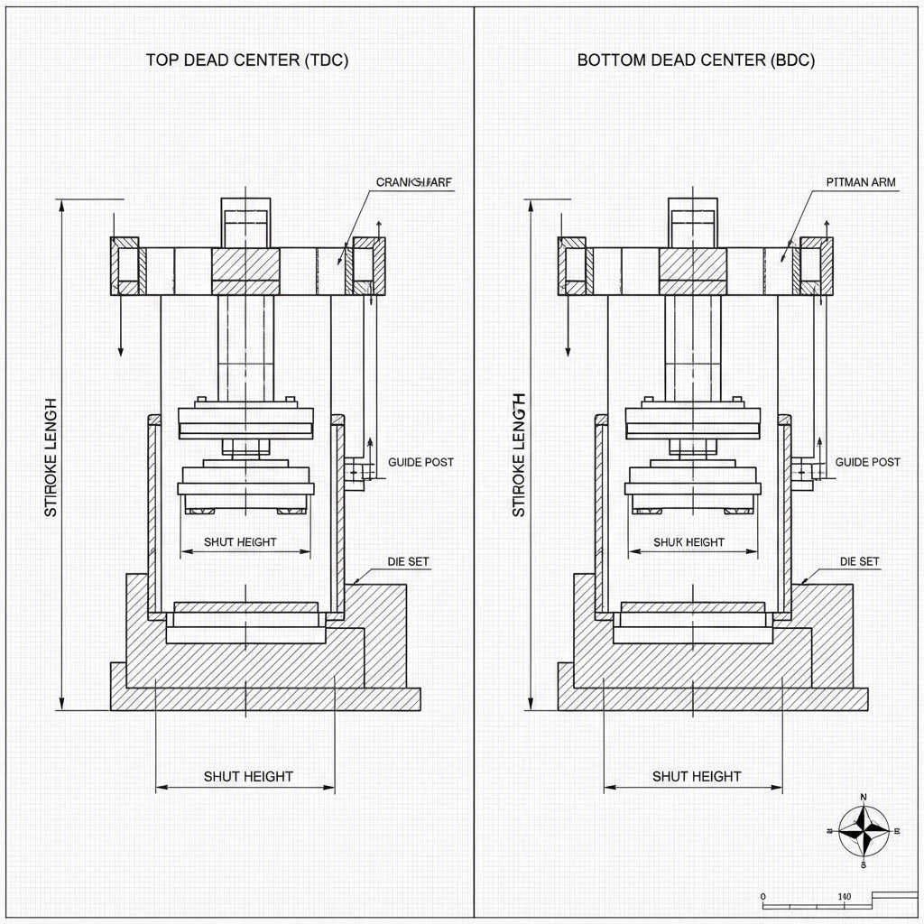
Before selecting specifications, it is critical to distinguish between press stroke and shut height, as these terms are frequently confused during equipment specification. Press stroke is the total vertical distance the slide travels from Top Dead Center (TDC) to Bottom Dead Center (BDC). It is a fixed characteristic of the machine’s crankshaft geometry (in mechanical presses) or a programmable variable (in servo/hydraulic presses).
Shut height, conversely, is the distance from the bottom of the slide to the top of the bolster plate when the stroke is at BDC. Shut height determines the maximum die height the press can accommodate, while stroke length determines the dynamic motion of the forming process.
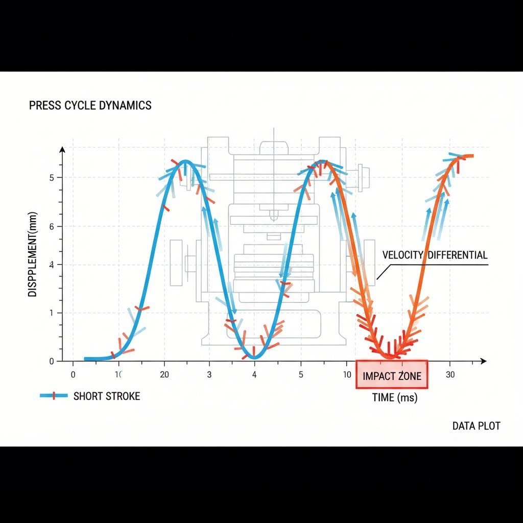
Understanding the sinusoidal motion of a mechanical press is essential for stroke selection. In a standard crank press, the slide does not move at a constant velocity. It accelerates from a stop at TDC, reaches maximum velocity at the 90-degree position (mid-stroke), and decelerates to zero at BDC. This physics profile means that stroke length directly dictates impact velocity. A longer stroke results in the ram traveling faster at the mid-point to cover the greater distance in the same amount of time, significantly increasing the kinetic energy transferred to the tooling upon contact.
The Case for Short Strokes: Blanking & High-Speed Productivity
For operations involving flat parts, progressive dies, or simple blanking, the engineering consensus is unequivocal: use the shortest possible stroke. Minimizing stroke length yields three critical engineering advantages that directly impact ROI and OEE (Overall Equipment Effectiveness).
1. Reduced Impact Velocity and Tool Wear
Tool life is often determined by the velocity at which the punch strikes the material. High impact velocities generate excessive heat and shock waves that cause premature chipping and punch fatigue. By reducing the stroke length, you effectively reduce the slide's velocity at the point of engagement.
Data indicates that reducing the stroke length by half can decrease impact velocity by approximately 28%. For example, a press running with a 40mm stroke might hit the material at 25mm/sec, whereas a 20mm stroke at the same SPM would impact at only 18mm/sec. This reduction drastically lowers the shock load on punches, significantly extending intervals between sharpening.
2. Increased Production Speed (SPM)
Shorter strokes allow for higher Strokes Per Minute (SPM) without exceeding the critical velocity limits of the tooling or the feed equipment. If you reduce the ram stroke from 1.0 inch to 0.5 inch, you can theoretically double the press SPM while maintaining a similar slide velocity profile. This is the primary driver for high-speed stamping of electrical terminals and motor laminations.
3. Optimized Feed Windows
In high-speed stamping, the limiting factor is often the feeder, not the press. The strip must advance only when the punches are clear of the material (the "feed window"). A shorter stroke maximizes the portion of the crank cycle available for feeding. With a short stroke, the punches clear the material faster on the upstroke and engage later on the downstroke, providing a wider crank angle window (e.g., 270° to 90°) for the servo feeder to index the material.
The Case for Long Strokes: Deep Drawing & Complex Forming
While short strokes offer speed, they are physically impossible for deep drawing applications. Here, the stroke length is non-negotiable and is governed by the physical dimensions of the part and the thermodynamics of the forming process.
The 2.5x Clearance Rule
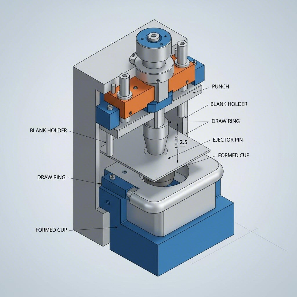
For deep drawn parts (cups, cans, housings), the primary constraint is part removal. You need enough vertical space to lift the finished part out of the die and clear the transfer system. The standard rule of thumb is:
Stroke Length ≥ 2.5 × Finished Part Height
For example, if you are drawing a beverage can that is 4 inches tall, you generally require a stroke of at least 10 inches. This accounts for the 4 inches of the part itself, the extraction lift, and the clearance needed for the transfer arm or feeder to move the part out without collision.
Energy and Torque Availability
Deep drawing requires sustained tonnage higher up in the stroke, long before the slide reaches BDC. Mechanical presses are rated for full tonnage only near the bottom (typically 30° above BDC). A longer stroke changes the torque curve, potentially reducing the available tonnage at the point of initial contact. When selecting a long-stroke press for drawing, engineers must verify the torque derating curve to ensure the press has sufficient energy (flywheel capacity) and torque to begin the draw inches above BDC without stalling.
Calculating the Optimal Stroke Length
Selecting the precise stroke involves a calculation matrix that considers feed time, part geometry, and press speed. Use the following logic flow to determine the specification:
- Step 1: Determine Minimum Clearance. For flat parts, this is simply the strip lift required to clear pilots. For formed parts, apply the 2.5x height rule.
-
Step 2: Calculate Feed Window Requirements. Determine how many degrees of the crank cycle are blocked by the tooling engaging the material.
Formula: Blocked Angle = 2 × arcsin( (Depth of Draw + Clearance) / (Stroke / 2) ). - Step 3: Evaluate Feed Speed. If the remaining "open" angle is insufficient for your feeder to index the pitch length at the desired SPM, you must either increase the stroke (to widen the window) or upgrade to a faster servo feeder.
- Step 4: Check Velocity Limits. Calculate the impact velocity at the proposed stroke and SPM. If it exceeds the tool steel's recommended limits (typically dependent on material type and thickness), you must reduce the stroke or SPM.
For manufacturers requiring extreme flexibility—such as automotive Tier 1 suppliers producing both flat brackets and deep-drawn housings—servo presses or hydraulic presses are often the superior choice. These machines allow for programmable stroke profiles, enabling a "short stroke" mode for blanking and a "long stroke" mode for drawing on the same equipment.
Operational Trade-offs: Velocity, Energy & Maintenance
The decision of press stroke length has long-term implications for maintenance and operational costs. Running a long-stroke press for short-stroke work (e.g., blanking flat washers on a 10-inch stroke press) is a common but costly error. The excess slide travel generates unnecessary friction, wastes flywheel energy, and forces the press to run slower than its potential.
| Feature | Short Stroke | Long Stroke |
|---|---|---|
| Primary Application | Blanking, Coining, High-Speed Lamination | Deep Drawing, Deep Bending, Trimming |
| Impact Velocity | Low (Better Tool Life) | High (Higher Tool Wear) |
| SPM Potential | High (Max Productivity) | Low (Limited by Velocity) |
| Energy Consumption | Efficient (Less Travel) | High (Excess Motion) |
Furthermore, maintaining press alignment becomes critical as stroke length increases. The side-thrust forces on the gibs are magnified in long-stroke operations, especially if the load is off-center. Regular maintenance of the gibs and lubrication system is non-negotiable for long-stroke machines.
For automotive manufacturers balancing these complex trade-offs, partnering with a specialized fabricator can often mitigate the risks of equipment mismatch. Companies like Shaoyi Metal Technology leverage advanced press capabilities up to 600 tons to manage diverse stroke requirements, delivering IATF 16949-certified components like control arms and subframes without the need for internal capital investment in specialized long-stroke machinery.
Frequently Asked Questions
1. Should we choose press speed based on productivity or maintenance?
While productivity (SPM) is the goal, maintenance should dictate the limit. Running a press faster than the tooling or feed system can handle will result in micro-stoppages, miss-feeds, and tool breakage that destroy OEE. It is better to run consistently at 80% of maximum speed than to run at 100% with frequent unplanned downtime.
2. What is the difference between press stroke and shut height?
Press stroke is the dynamic distance the ram travels from top to bottom (TDC to BDC). Shut height is the static space available for the die when the ram is at its lowest point (BDC). Increasing the stroke length does not change the shut height, but adjusting the slide adjustment screw changes the shut height without altering the stroke length.
3. Why is a shorter press stroke better for tool life?
A shorter stroke reduces the impact velocity of the punch engaging the material. Because the ram has less distance to travel in the same amount of time, it moves slower at the point of impact. This reduction in kinetic energy transfer minimizes shock, heat generation, and abrasive wear on the cutting edges.