 Maliit na mga batch, mataas na pamantayan. Ang serbisyo sa paggawa ng mabilis na prototyping namin ay gumagawa ng mas mabilis at mas madali ang pagpapatunay —

Ang Pagmamanufacture ng Dies: Mula sa Hilaw na Bakal Hanggang sa mga Kagamitang Handa na para sa Produksyon
Ano ang die sa pagmamanupaktura
Ano ang isang die sa pagmamanupaktura? Sa madaling salita, ang isang die ay isang espesyal na kasangkapan na idinisenyo upang putulin, hugpian, o ibaon ang mga materyales sa mga tiyak na anyo sa ilalim ng aplikadong presyon. Hindi tulad ng mga pangkalahatang kasangkapan, ang mga die ay may mataas na kahusayan sa paggawa para sa paulit-ulit na , mataas na dami ng produksyon ng mga identikal na bahagi. Kung ikaw man ay nagpapandurog ng mga panel ng katawan ng sasakyan o nagpuputol ng mga kumplikadong gasket, mahalaga ang pag-unawa sa kung ano ang mga die at kung paano sila gumagana para sa sinumang kabilang sa mga operasyon ng modernong pagmamanupaktura.
Ang isang die ay isang pasadyang idinisenyong kasangkapan na ginagamit sa pagmamanupaktura upang hugpian, putulin, o ibaon ang mga materyales—tulad ng metal, plastik, o goma—sa isang tiyak na hugis o sukat sa pamamagitan ng aplikasyon ng puwersa.
Ang Depinisyon ng Manufacturing Die
Kaya, ano nga ba ang die? Ang kahulugan ng die na ginagamit ng mga propesyonal ay tumutukoy sa isang pinalalakas na kagamitan na gumagana kasama ang isang press o makina upang baguhin ang mga hilaw na materyales sa mga natapos na bahagi. Ginagamit ang isang die para gawin ang mga operasyon tulad ng blanking, piercing, bending, at forming—bawat isa ay nangangailangan ng tiyak na inhinyeriya upang makamit ang pare-parehong resulta.
Isipin ito nang ganito: kapag gumagamit ka ng isang cookie cutter, ginagamit mo sa katunayan ang isang simpleng die. Ang mga industrial die ay sumusunod sa parehong prinsipyo ngunit gumagana sa ilalim ng napakalaking presyon at nakakamit ang mga toleransya na sinusukat sa libong bahagi ng isang pulgada. Karaniwang binubuo ang isang die ng dalawang pangunahing bahagi—ang punch (na naglalapat ng puwersa) at ang die block (na tumatanggap at binubuo ang materyales). Kasama-sama, ang mga elemento na ito ay gumagana upang makabuo ng mga bahagi na may napakadakilang katiyakan.
Bakit Mahalaga ang mga Die sa Modernong Produksyon
Bakit dapat kang mag-alala sa paggawa ng die? Isipin ito: halos bawat metal o plastik na bahagi na ginagamit sa masa ay nabuo gamit ang isang die sa ilang punto. Mula sa smartphone sa iyong bulsa hanggang sa sasakyan na pinapatakbo mo, ang mga die ang nagpapahintulot sa pare-parehong at mura na produksyon na kailangan ng modernong pagmamanupaktura.
Ang kahalagahan ng mga die sa pagmamanupaktura ay nakasalalay sa tatlong mahahalagang kadahilanan:
- Konsistensi: Kapag maayos nang inenginyero, ang isang die ay gumagawa ng mga identikal na bahagi sa bawat siklo, na nagtiyak ng kontrol sa kalidad sa daan-daang milyong yunit
- Kahusayan: Ang mga die ay nagpapahintulot sa mabilis na bilis ng produksyon na hindi kayang tularan ng manu-manong paggawa
- Cost-effectiveness: Bagaman ang paunang pamumuhunan sa tooling ay maaaring malaki, ang gastos bawat bahagi ay napakahina sa mataas na dami ng produksyon
Mula sa Hilaw na Materyal hanggang sa Precision Part
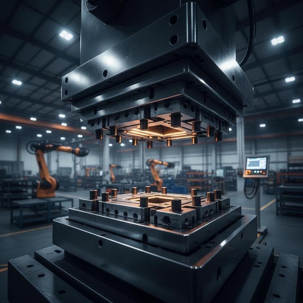
Ang pag-unawa kung ano ang paggawa ng die ay nangangahulugan din ng pag-unawa kung paano ginagamit ang mga kasangkapang ito upang baguhin ang hilaw na materyales sa mga natapos na bahagi. Ang proseso ay nagsisimula kapag pumapasok ang sheet metal, wire, o iba pang materyales sa press. Ang die ay naglalapat ng kontroladong puwersa—na minsan ay umaabot sa daan-daang tonelada—upang hugpuin ang materyales nang may katiyakan.
Ang mga operasyon sa paghuhubog ay umaasa sa mekanikal na katangian ng materyales, gamit ang compression, tension, o pareho upang makamit ang ninanais na hugis. Sa mga aplikasyon ng sheet metal tulad ng mga bahagi ng katawan ng sasakyan, ang punch ay gumagawa ng mga operasyon sa pagpapahaba at pagpapalukoy habang ang die block ay mahigpit na pinipigilan ang workpiece. Ang koordinadong aksyon na ito ay nagsisiguro ng katiyakan sa sukat at kalidad ng ibabaw na sumusunod sa mahigpit na mga pamantayan ng industriya.
Ano ang panghuling tungkulin ng mga die? Sila ang nagsisilbing tulay sa pagitan ng mga hilaw na materyales at ng mga bahaging may kahusayan na gumagana sa lahat ng bagay, mula sa mga kagamitang elektroniko para sa konsyumer hanggang sa mga sistema ng aerospace. Sa mga kabanata na darating, matutuklasan mo ang iba't ibang uri ng mga die, kung paano sila ginagawa, at anong mga salik ang tumutukoy sa tagumpay ng iyong mga aplikasyon sa produksyon.
Mga Uri ng Die na Ginagamit sa mga Industriyal na Aplikasyon
Ngayong nauunawaan mo na kung ano ang isang die, ang susunod na lohikal na tanong ay: aling uri ang talaga mong kailangan? Ang sagot ay ganap na nakasalalay sa iyong mga kinakailangan sa produksyon, sa mga tukoy na katangian ng materyales, at sa huling gamit ng produkto. Ang bawat uri ng die ay may tiyak na layunin sa iba't ibang sektor ng pagmamanupaktura, at ang maling pagpili ng die ay maaaring magdulot ng malaking pagkakaiba sa pagitan ng kapaki-pakinabang na produksyon at ng mahal na pag-uulit ng proseso.
Ang pag-unawa sa iba't ibang uri ng die na available ay tumutulong sa iyo na gumawa ng impormadong desisyon tungkol sa mga investisyon sa tooling. Tingnan natin ang pangunahing kategorya at alamin kung kailan ang bawat isa ay pinakamainam para sa iyong operasyon.
Mga Paltik sa Pagpaprisma para sa mga Operasyon sa Sheet Metal
Kapag ang usapan ay tungkol sa mataas na dami ng produksyon ng sheet metal, ang mga paltik sa pagpaprisma ang nangunguna sa larangan . Ang mga paltik na ito sa pagpaprisma ng metal ay nagbabago ng patag na sheet stock sa mga bahagi na may tatlong dimensyon sa pamamagitan ng kombinasyon ng mga operasyon sa pagputol at pagbuo. Makikita mo sila na gumagana sa lahat ng bagay mula sa mga kahon ng appliance hanggang sa mga istruktural na bahagi ng sasakyan.
Ang kategorya ng mga paltik sa pagpaprisma ay kasama ang ilang magkakaibang konpigurasyon:
- Mga simpleng die: Gumagawa ng isang operasyon bawat pindot ng press—angkop para sa pangunahing blanking o piercing kapag ang dami ng produksyon ay hindi sapat upang patunayan ang kailangan ng kumplikadong tooling
- Compound dies: Nagpapatakbo ng maramihang operasyon sa pagputol nang sabay-sabay sa isang pindot, na binabawasan ang paghawak at pinapabuti ang katiyakan ng bahagi
- Progressive Dies: Mayroong maraming estasyon na nagpapatakbo ng sunud-sunod na operasyon habang ang materyal ay pumapasok sa loob ng press—perpekto para sa mga kumplikadong bahagi na nangangailangan ng maraming hakbang sa pagbuo
- Transfer dies: Katulad ng progressive tooling ngunit gumagamit ng mekanikal na sistema para ilipat ang mga pre-cut na blank sa pagitan ng mga estasyon, na sumasaklaw sa mas malalaki o mas kumplikadong heometriya
Para sa mga propesyonal sa pagmamanupaktura na sinusuri ang mga metal stamping die, ang dami ng produksyon ang pangunahing salik na nagpapasiya. Ang mga simpleng die ay epektibo para sa paggawa ng prototype o mga maliit na batch, samantalang ang progressive at transfer na konfigurasyon ang nagbibigay ng bilis at pagkakasunod-sunod na kailangan sa mataas na dami ng produksyon.
Mga Drawing Die para sa Produksyon ng Wire at Tube
Nagtanong na ba kayo kung paano nakakakuha ang copper wire ng tiyak na diameter nito o kung paano pinapanatili ng seamless tubing ang pantay na kapal ng pader? Ang mga drawing die ang nagpapagana nito. Ang mga espesyalisadong kasangkapan na ito ay binabawasan ang cross-section ng materyal sa pamamagitan ng paghila ng stock sa loob ng isang hugis na bukas, na lumilikha ng mga produkto na may napakahusay na pagkakasunod-sunod sa sukat.
Ang mga drawing operation ay umaasa sa tensile forces imbes na sa compression, na siyang naghihiwalay sa kanila sa mga stamping application. Ang panloob na geometry ng die—na karaniwang may bell-shaped na pasukan, isang working cone, at isang sizing land—ang tumutukoy sa huling sukat at surface finish ng inilalabas na produkto.
Mga pangunahing aplikasyon ng drawing die ay kinabibilangan ng:
- Produksyon ng kable para sa mga aplikasyon sa kuryente, konstruksyon, at industriya
- Mga seamless na tubo para sa mga sistema ng hidrauliko, medikal na device, at heat exchanger
- Mga deep-drawn na komponente tulad ng mga lata ng inumin, kagamitan sa pagluluto, at mga tangke ng gasolina para sa sasakyan
Ang pagpili ng materyal para sa mga drawing die ay nakabase nang husto sa produkto na binubuo. Ang mga die na gawa sa tungsten carbide ay mahusay sa wire drawing kung saan ang labis na kahigpit ay tumutol sa pagsusuot, samantalang ang mga die na gawa sa tool steel ay karaniwang ginagamit sa deep drawing kung saan ang kontroladong daloy ng materyal ay nagpipigil sa pagkaburak.
Mga Cutting Die para sa Presisyong Paghubog
Kapag ang iyong aplikasyon ay nangangailangan ng malinis at eksaktong mga gilid nang walang karagdagang paghubog, ang mga cutting die ang nagbibigay ng ganitong resulta. Kasama sa kategoryang ito ang lahat mula sa mga industrial na metal die configuration hanggang sa mga fabric cutting die na ginagamit sa mga operasyon sa textile at packaging.
Ang pamilya ng cutting die ay binubuo ng dalawang pangunahing paraan ng paggawa:
- Mga steel rule dies: May mga sharpened na bakal na blade na nakakabit sa isang substrate—mura at epektibo para sa mas malalambot na materyales tulad ng papel, foam, gaskets, at tela
- Forged/Machined Dies: Solidong tool steel o konstruksyon na gawa sa karbida para sa mga demanding na aplikasyon sa pagputol ng metal na nangangailangan ng mahigpit na toleransya at mas mahabang buhay ng kagamitan
Ang mga dies na gawa sa bakal na ruler ay nag-aalok ng malaking bentahe sa gastos para sa mga di-metalikong materyales. Halimbawa, ang mga dies para sa pagputol ng tela ay karaniwang gumagamit ng ganitong konstruksyon dahil ang mas malambot na substrate ay hindi nangangailangan ng kahigpitang katumbas ng isinagawang tooling. Gayunpaman, kapag pinuputol ang metal o pinoproseso ang mga abrasive na materyales, ang mga machined dies mula sa hardened tool steel ay nabibigyan ng katuwiran ang kanilang mas mataas na presyo dahil sa kanilang superior na tibay at kumpiyansa sa presisyon.
| Uri ng die | Pangunahing tungkulin | Karaniwang Materyales na Pinoproseso | Typikal na Industriya |
|---|---|---|---|
| Stamping Dies (Progressive/Transfer) | Pagpapadulas at pagbuo ng sheet metal sa pamamagitan ng sunud-sunod na operasyon | Bakal, aluminum, stainless steel, copper alloys | Automotive, appliances, electronics, HVAC |
| Paglalagay ng matuying | Pagbabawas ng cross-sections sa pamamagitan ng tensile forming | Copper, aluminum, bakal na wire, sheet metal para sa deep drawing | Electrical, packaging, automotive, medical devices |
| Mga Puthaw na Pumuputol (Steel Rule) | Pangunahing pagputol ng mga di-metalikong materyales | Papel, karton, puma, goma, tela, at mga materyales para sa gasket | Pakete, tekstil, pagpapaimprenta, at paggawa ng gasket |
| Mga Puthaw na Pumuputol (Na-hulog o Na-machined) | Pagputol at pagbuburak ng metal na may mataas na kahusayan | Asero, stainless steel, titanium, at espesyal na alloys | Aerospasyo, depensa, at mahusay na pagmamanupaktura |
| Mga Forging Die | Paghubog ng mainit na metal gamit ang puwersang pindutin | Asero, aluminum, titanium, at mga superalloy | Automotive, aerospasyo, langis at gas, at malalaking kagamitan |
| Molding dies | Paglikha ng mga kavidad ng hulma para sa pagsisipat ng tinunaw na metal | Aluminum, sosa, magnesiyo na haluang metal | Automotive, consumer electronics, industriyal na kagamitan |
Bukod sa mga aplikasyon sa pagputol at pagbuo, ang mga hugis-pandikit (forging dies) at mga hugis-pagkast (casting dies) ay kumakatawan sa buong larangan ng industriyal na kagamitang pandukha. Ang mga hugis-pandikit ay nagbibigay ng hugis sa mga billet na metal na mainit sa ilalim ng matinding pwersang pindutin, na gumagawa ng mga bahagi na may mahusay na istruktura ng butil at mekanikal na katangian—tulad ng crankshafts, connecting rods, at turbine blades. Samantala, ang mga hugis-pagkast ay ginagamit sa mga operasyon ng die casting kung saan ang tinunaw na metal ay puno sa mga kavidad na may mataas na presisyon upang makabuo ng mga bahaging malapit na sa huling hugis (near-net-shape).
Para sa mga propesyonal sa pagmamanupaktura na binibigyang pansin ang kanilang mga opsyon, ang matrix ng desisyon ay nakasalalay sa ilang magkaugnay na kadahilanan: ang materyal na pinoproseso, ang kumplikado ng heometriya ng bahagi, ang kinakailangang toleransya, ang dami ng produksyon, at ang mga limitasyon sa badyet. Ang isang metal na hugis na idinisenyo para sa mga panel ng katawan ng sasakyan ay nangangailangan ng iba’t ibang mga konsiderasyon sa disenyo kumpara sa mga kagamitang pandukha na ginawa para sa mga kabalang elektroniko o sa mga komponente ng estruktura ng aerospace.
Sa pamamagitan ng malinaw na pag-unawa sa mga uri ng die at kanilang mga aplikasyon, ang susunod na hakbang ay ang pagsusuri kung paano talaga nabubuo ang mga eksaktong kasangkapan na ito—mula sa unang konsepto hanggang sa tooling na handa nang gamitin sa produksyon.
Buong Proseso ng Pagmamanupaktura ng Die
Kaya naman, natukoy mo na ang uri ng die na kailangan mo—ano ang susunod? Ang pag-unawa kung ano ang die making at kung paano nababago ang mga eksaktong kasangkapang ito mula sa mga konsepto sa engineering patungo sa kagamitang handa nang gamitin sa produksyon ay nagbibigay sa iyo ng kaalaman upang suriin ang mga tagapag-suplay, itakda ang mga realistiko at makatotohanang timeline, at hulaan ang mga resulta sa kalidad. Ang proseso ng paggawa ng die ay binubuo ng maraming magkakaugnay na yugto, kung saan ang bawat isa ay nakabase sa nakaraang yugto upang makabuo ng tooling na kakayahang mag-produce ng milyon-milyong bahagi na pare-pareho ang kalidad .
Subukan nating daanin ang buong biyahe mula sa unang mga teknikal na tukoy hanggang sa isang ganap na operasyonal na die na handa nang ilagay sa iyong production floor.
Yugto ng Disenyo at CAD Engineering
Ang bawat matagumpay na die ay nagsisimula sa masinsin na pagdidisenyo. Ang yugtong ito ang nagtatayo ng pundasyon para sa lahat ng susunod na hakbang, at ang anumang shortcut dito ay tiyak na magdudulot ng mga problema sa susunod na yugto. Ang modernong paggawa ng die ay umaasa nang husto sa software ng Computer-Aided Design (CAD) na nagpapahintulot sa mga inhinyero na lumikha ng detalyadong 3D na modelo na sumasaklaw sa bawat mahalagang sukat at toleransya.
Sa panahon ng pag-unlad ng die drawing, sinusuri ng mga inhinyero ang mga kinakailangan sa iyong bahagi at gumagawa ng reverse engineering upang matukoy ang pinakamainam na geometry ng die. Tinatantya nila ang mga salik tulad ng ugali ng daloy ng materyal, kompensasyon para sa springback, at bilang ng mga kailangang yugto ng pagbuo. Para sa mga kumplikadong bahagi, maaaring kasali sa pagsusuring ito ang sopistikadong Computer-Aided Engineering (CAE) simulation na hinahatulan kung paano mag-uugali ang sheet metal sa panahon ng mga operasyon ng pagbuo.
Bakit mahalaga ang simulation? Pagsusuri ng Keysight sa pagbuo ng sheet metal , ang mga depekto ay kadalasang lumilitaw lamang sa panimulang mga pagsubok sa yugto ng pagsubok—kung saan ang mga pagwawasto ay parehong mahabang proseso at mahal. Ang mga virtual na pagsubok sa dies sa pamamagitan ng CAE simulation ay nakikilala ang mga potensyal na isyu tulad ng pagkukurba, pagkabuwal, o labis na pagbabalik (springback) bago pa man i-cut ang anumang metal, na nagpapababa nang malaki sa mga siklo ng pag-unlad at sa mga gastos sa tooling.
Pinos na Pagmamasin at Pagpapainit
Kapag natapos na ang mga disenyo, ang proseso ng paggawa ng die ay lumilipat sa pisikal na produksyon. Ang yugtong ito ay nagpapalit sa mga hilaw na tool steel o carbide blanks tungo sa mga pinos na komponente sa pamamagitan ng isang maingat na inorganisang serye ng mga operasyon.
Ito ang karaniwang pagkakasunod-sunod ng paggawa para sa paggawa ng tool die:
- Pagsusuri ng Mga Tiyak na Spesipikasyon sa Disenyo: Huling pagsusuri ng lahat ng kinakailangang sukat, toleransya, at mga tawag sa materyales
- CAD/CAM Modeling: Pagbuo ng mga toolpath at mga programa sa pagmamasin mula sa mga aprobadong 3D model
- Pagpili ng materyal: Pagbili ng angkop na mga grado ng tool steel (karaniwan ay D2, A2, o H13) batay sa mga kinakailangan ng aplikasyon
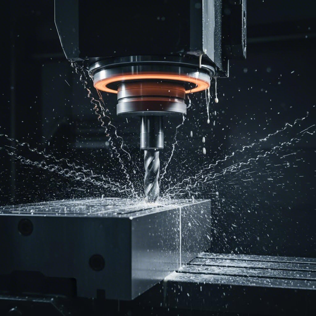
- Rough Machining: Ang CNC milling ay nag-aalis ng malaking dami ng materyal hanggang sa 0.010–0.020 pulgada lamang mula sa panghuling mga sukat
- Pagsilaw sa Init: Ang mga proseso ng pagpapalasa at pagpapahina (hardening and tempering) ay nakakamit ang target na kahigpit (karaniwang 58–62 HRC para sa mga aplikasyon sa pagputol)
- Precision Grinding: Ang mga operasyon sa surface grinding at cylindrical grinding ay nakakamit ang panghuling mga sukat na may katumpakan hanggang 0.0005 pulgada
- Mga Operasyon sa EDM: Ang wire EDM at sinker EDM ay gumagawa ng mga kumplikadong anyo at mga bukas na bahagi na may mahigpit na toleransya
- Pagsasaayos: Ang mga komponente ay isinasama nang maayos gamit ang mga gabay na pako (guide pins), mga plato sa pag-alis (stripper plates), at mga suportang komponente (backing components)
- Veripikasyon ng kalidad: Ang komprehensibong inspeksyon ay nagpapatunay na natutugunan ang lahat ng mga teknikal na tukoy bago ito ipinapalabas
Ang pagmamasin ng die ay nangangailangan ng labis na kahusayan sa buong sekwensyang ito. Ang ugnayan sa pagitan ng clearance ng punch at die—na karaniwang nasa hanay na 5% hanggang 15% ng kapal ng materyal depende sa operasyon—ay direktang tumutukoy sa kalidad ng bahagi. Ang kulang na clearance ay nagdudulot ng labis na pagsuot ng kagamitan at pagbuo ng burr, samantalang ang sobrang clearance ay nagreresulta sa mahinang kalidad ng gilid at pagkakaiba-iba sa mga sukat.
Ang pagpapainit ay isang lubhang mahalagang hakbang sa pagmamasin ng mga bahagi ng die. Ang proseso ay kasali ang pagpainitin ng tool steel sa mga temperatura na lampas sa 1,800°F, na sinusundan ng kontroladong pagpapalamig at mga siklo ng pagpapatibay. Ito ay nagbabago sa kristalinong istruktura ng materyal, na nakakamit ang kahigpitang kailangan upang tumagal ng milyon-milyong siklo ng produksyon habang nananatiling sapat ang kahigpitang pang-impact upang maiwasan ang pagkabali o pagsira.
Pagsusuri ng Kalidad at Panghuling Pagwawasto
Ang mga huling yugto ng pagpoproseso ng die ay nakatuon sa pagpapahusay at pagpapatunay. Ang mga operasyon sa pagpipinong ibabaw tulad ng pagpapakinis at paglalagay ng lap ay nagsisiguro ng makinis na daloy ng materyal habang nasa produksyon. Maaaring ilagay ang mga coating tulad ng titanium nitride (TiN) o diamond-like carbon (DLC) upang bawasan ang panlabas na pwersa (friction) at palawigin ang buhay ng kasangkapan.
Ang pagpapatunay ng kalidad ay kumakatawan sa pagsusuri ng sukat gamit ang mga coordinate measuring machine (CMM) na nagpapatunay na ang mga mahahalagang katangian ay sumusunod sa mga tukoy na pamantayan. Para sa mga stamping die, ang mga pagsusubok ay gumagawa ng mga sample na bahagi na sinusuri nang lubusan para sa katiyakan ng sukat, kalidad ng ibabaw, at kawalan ng mga depekto.
Ang pag-unawa sa proseso ng die na ito ay makatutulong upang mapahalagahan mo kung bakit ang mga lead time para sa mga high-precision tooling ay kadalasang umaabot sa ilang linggo o buwan—at kung bakit ang pagpapabilis sa anumang yugto ay maaaring magdulot ng panganib sa pagganap at haba ng buhay ng tool. Dahil malinaw na ang buong paggawa ng serye, tingnan natin ang mga indibidwal na bahagi na bumubuo sa isang gumagana nang maayos na sistema ng die at kung paano sila sama-samang gumagana habang nasa produksyon.
Mga Pangunahing Bahagi ng Die at Paano Sila Nagkakasama
Nakita mo na kung paano ginagawa ang mga die—ngunit ano nga ba ang binubuo ng mga eksaktong kasangkapan na ito? Ang pag-unawa sa mga bahagi ng die at sa kanilang ugnayan sa isa't isa ay nagbabago sa paraan kung paano mo sinusuri ang kalidad ng mga kasangkapan, nalulutas ang mga isyu sa produksyon, at nakikipag-usap sa mga tagapag-suplay. Isipin ang isang gumagana nang maayos na sistema ng die tulad ng isang maayos na ino-orchestrate na koponan: bawat bahagi ay may tiyak na tungkulin, at ang buong operasyon ay nakasalalay sa perpektong koordinasyon sa pagitan ng mga bahagi.
Kaya ano nga ba talaga ang konstruksyon ng die tool? Subukin nating i-break down ang mga pangunahing elemento na sama-samang gumagana upang baguhin ang mga hilaw na materyales sa mga bahaging may mataas na presisyon .
Mekanika ng Die Block at Punch
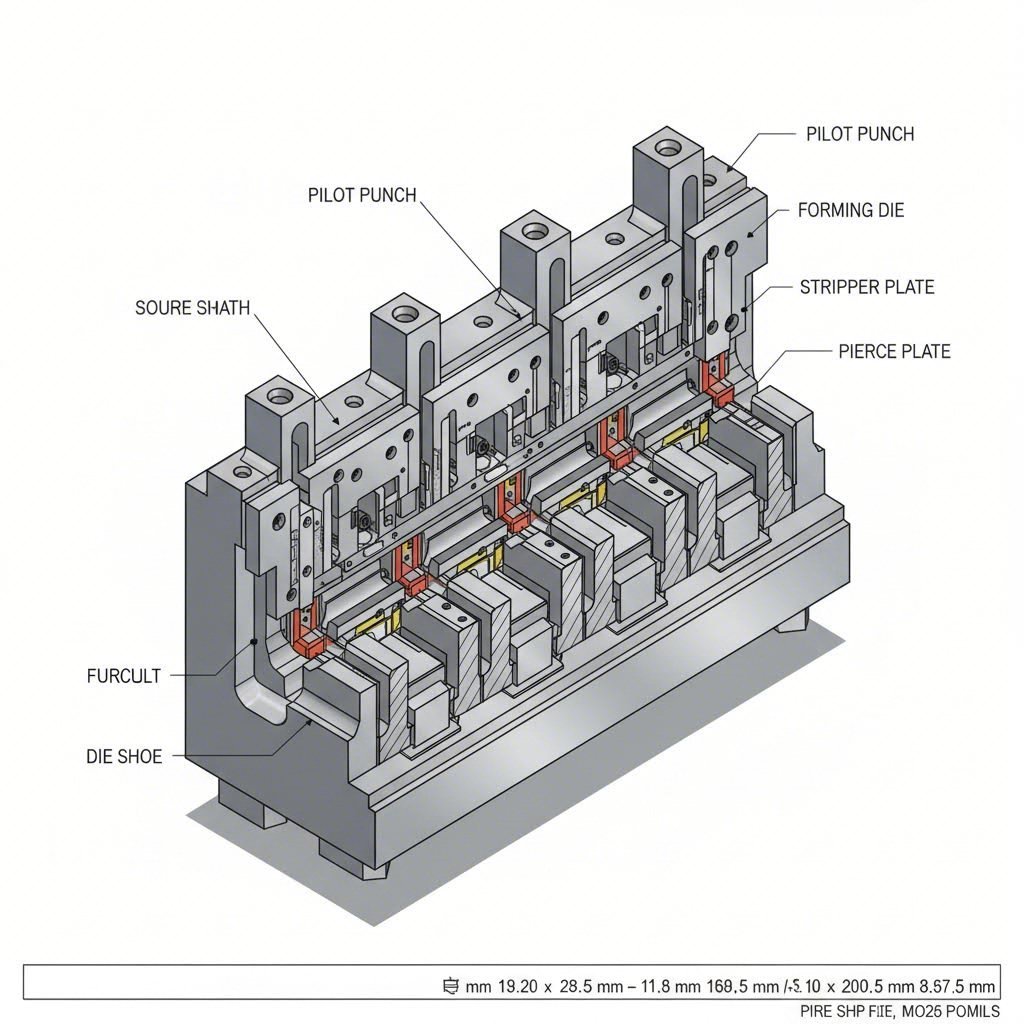
Sa puso ng bawat operasyon ng press tool ay matatagpuan ang pundamental na ugnayan ng punch at die. Ang dalawang bahaging ito ay gumagana bilang magkasalungat na kapartner—ang punch ang naglalapat ng puwersa mula sa itaas habang ang die block ang tumatanggap at bumubuo sa materyal mula sa ibaba.
Ang die Block (minsan tinatawag na die button) ay naglalaman ng hugis na bukana na nagtatakda sa geometry ng iyong bahagi. Kapag pumasok ang materyal sa pagitan ng punch at die, ang die block ang nagbibigay ng gilid na pangputol at sumusuporta sa workpiece habang isinasagawa ang mga operasyon sa pagbuo. Karaniwang ginagawa ang mga die block mula sa hardened tool steel upang matagpuan ang paulit-ulit na pwersa ng impact sa mataas na dami ng produksyon.
Ang die punch ay ang kasangkapan na direktang nakikipag-ugnayan at binabago ang materyal. Ayon sa Moeller Precision Tool, ang mga die punch ay maaaring magpabend o magpaputol ng mga butas sa metal depende sa hugis ng kanilang ilong—ang mga available na configuration ay kinabibilangan ng bilog, oblong, parisukat, parihaba, hexagonal, at mga custom na geometry.
Narito kung saan naging napakahalaga ang kahusayan: ang clearance sa pagitan ng punch at die ang nagtatakda sa kalidad ng bahagi. Ang "die break" na ito ay karaniwang umaabot sa 5–10% ng kapal ng materyal na pinoproseso. Imahein ang pagputol ng papel gamit ang mga gunting na hindi pantay kumpara sa mga talim na maasim—ang hindi tamang clearance ay nagdudulot ng katulad na problema:
- Hindi sapat na clearance: Nagdudulot ng labis na pagkasira ng kagamitan, pagbuo ng mga burr, at dagdag na pangangailangan sa toneladang presyon
- Labis na clearance: Nagbubunga ng mahinang kalidad ng gilid, pagkakaiba-iba sa sukat, at sekondaryong mga burr
- Optimal clearance: Nakakamit ang malinis na pagputol nang may kaunting burr at pare-parehong sukat ng bahagi
Mga Sistema ng Gabay at Mga Komponent para sa Pag-aalign
Ang eksaktong pag-aayos ay naghihiwalay sa de-kalidad na kagamitan mula sa mga problema sa die. Kahit ang pinakamaliit na pagkawala ng pagkakasunod-sunod sa pagitan ng itaas at ibabang bahagi ng die ay nagdudulot ng hindi pantay na pagsuot, pagbabago sa sukat, at maagang pagkabigo ng kagamitan. Dito ginagampanan ng mga sistema ng gabay ang kanilang tungkulin.
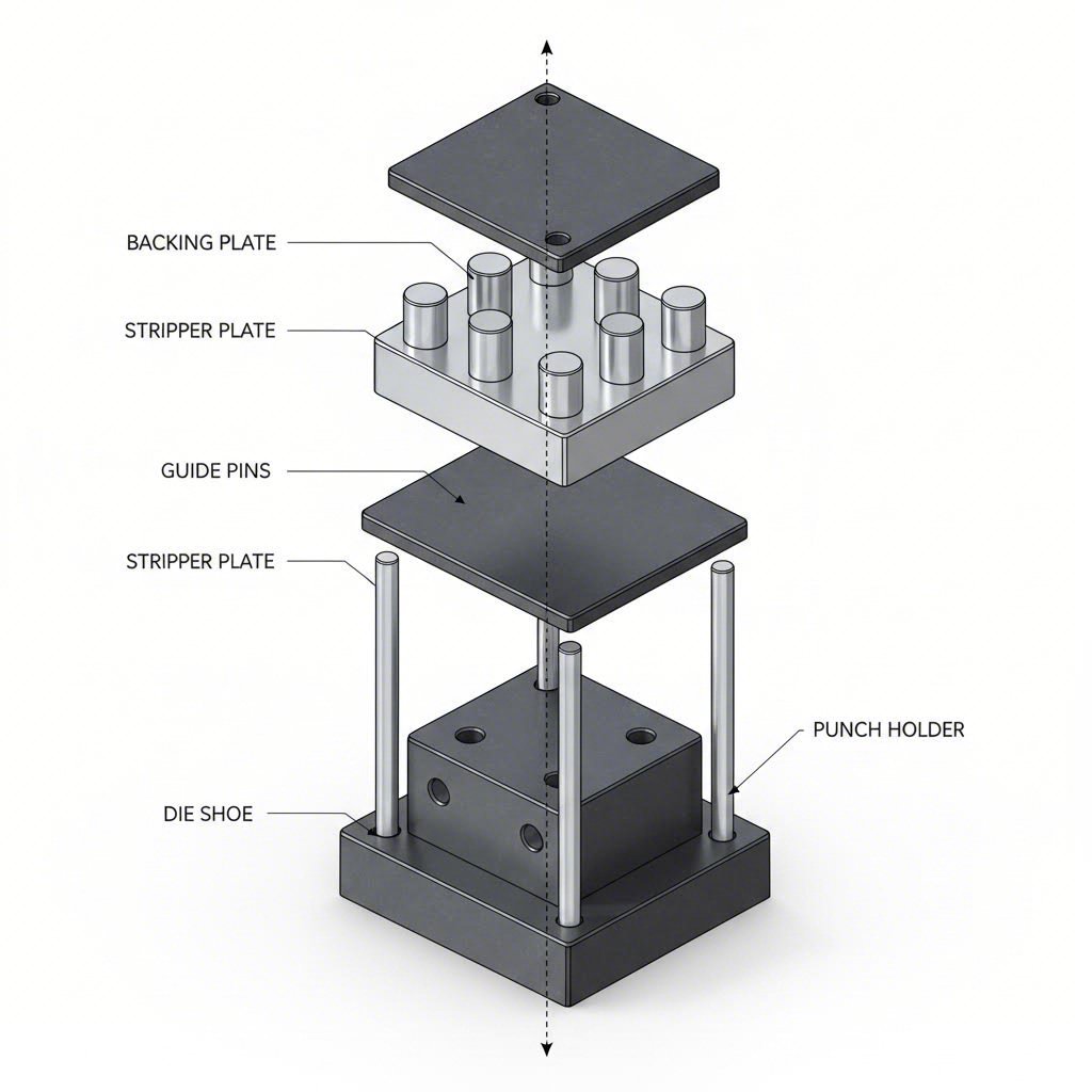
Ang mga pangunahing bahagi ng pag-aayos ay kinabibilangan ng:
- Die Shoe (Mga Plate ng Die): Ang mga ito ang nagsisilbing pundasyon kung saan nakakabit ang lahat ng iba pang bahagi. Ang mga pamantayan ng industriya ay karaniwang nagsasaad ng paggamit ng bakal, bagaman ang aluminum ay may kalamangan sa timbang para sa ilang aplikasyon
- Mga gabay na pasak: Mga poste na pinapakinis nang may kahusayan upang i-align ang itaas at ibabang seksyon ng die—ginawa ayon sa toleransya na loob ng 0.0001" (isang sampung libong bahagi ng isang pulgada)
- Mga gabay na bushing: Mga hardened na sleeve na tumatanggap ng mga guide pin, na magagamit sa mga bersyon na may friction-fit o ball-bearing
- Mga Backing Plate: Mga komponente para sa pagpapalakas na nagpapamahagi ng mga puwersa ng pagsusulok at nagpipigil sa pinsala sa die shoe
Kapag sinusuri ang kalidad ng tool at die, ang konstruksyon ng sistema ng alignment ay nagbibigay ng malinaw na impormasyon. Ang mga ball-bearing guide pin ay naging pamantayan na ng industriya dahil ginagawang mas madali ang paghihiwalay ng die sa panahon ng pagpapanatili habang pinapanatili ang tumpak na posisyon sa buong produksyon. Ang mga friction pin ay nananatiling ginagamit sa mga aplikasyon na nangangailangan ng maximum na rigidity, bagaman mas mahirap paghiwalayin para sa pagpapanatili.
Mga Stripper at Mekanismo ng Pag-eject
Nakatanong ka na ba kung paano ang mga bahagi ay malaya at malinis na inilalabas matapos ang pagbuo? Ang mga stripper at sistema ng pag-eject ang nangangasiwa sa mahalagang tungkuling ito. Kung walang tamang aksyon ng stripping, ang mga bahagi ay kumakapit sa mga punch, na nagdudulot ng mga pagkakaharang, pinsala, at pagkaantala sa produksyon.
Mga plato ng stripper hawakan ang materyal ng workpiece nang patag laban sa ibabaw ng die habang ang mga punch ay umuwithdraw. Ginagampanan nila ang dalawang tungkulin: panatilihin ang posisyon ng materyal habang ginagawa ang pagbuo at alisin ang mga natapos na bahagi mula sa tooling. Ang mga stripper na may spring-loaded ay naglalapat ng pare-parehong presyon sa buong stroke cycle, na umaangkop sa mga pagbabago sa kapal ng materyal.
Mga Spring ng Die nagpapatakbo ng mga function na stripping at ejection. Ang dalawang pangunahing uri—mga mekanikal na wire coil springs at mga nitrogen gas springs—ay may kani-kaniyang natatanging mga pakinabang. Ang mga nitrogen gas spring ay nagbibigay ng mas pare-parehong puwersa sa buong kanilang stroke at kumuha ng mas kaunti lamang na espasyo, samantalang ang mga mekanikal na spring ay nag-aalok ng kadalian at mas mababang gastos sa pagpapalit.
Kasali sa karagdagang mga komponente ng ejection ang:
- Mga Panatili ng Die: Pananatilihin ang mga cutting at forming component (mga punch, mga button) nang ligtas sa posisyon—magagamit sa mga bersyon na ball-lock, shoulder, trumpet head, at retractable
- Knockout Pins: Itulak ang mga nabuo na bahagi palabas sa mga die cavity matapos ang paggawa
- Mga sistema ng hangin na pumuputok: Gumagamit ng compressed air upang linisin ang maliit na mga bahagi at scrap mula sa lugar ng die
Ang pag-unawa sa kahulugan ng tool at die ay naging mas malinaw kapag sinusuri mo kung paano gumagana ang mga bahaging ito bilang isang pinagsamang sistema. Sa terminolohiyang pang-industriya, ang "tool" ay madalas na tumutukoy sa buong pagsasaayos—kabilang ang mga punch, mga gabay, mga stripper, at lahat ng suportadong hardware—samantalang ang "die" ay partikular na naglalarawan sa hugis na bukas na nagtatakda sa heometriya ng bahagi. Ang isang buong kakamit na pambabasa pagsasaayos ay nag-uugnay ng parehong elemento kasama ang mga sistemang mekanikal na kailangan para sa awtomatikong operasyon.
Ang ganitong pag-unawa sa antas ng bahagi ay naghihanda sa iyo upang suriin ang kalidad ng die, matukoy ang mga isyu sa produksyon, at makipag-ugnayan nang epektibo sa mga tagapag-suplay ng tooling. Kapag malinaw na ang mekanika, tingnan natin kung paano ginagamit ng iba't ibang industriya ang mga sistemang ito para sa kanilang tiyak na mga hamon sa pagmamanupaktura.
Mga Aplikasyon sa Industriya para sa Precision Die Tooling
Ngayon na naiintindihan na ninyo ang mga bahagi ng die at kung paano sila gumagana nang sama-sama, narito ang praktikal na tanong: Paano nga ba ginagampanan ng mga sistemang ito sa iba't ibang sektor ng pagmamanupaktura? Ang sagot ay nagpapakita kung bakit ang isang die para sa pagmamanupaktura ng mga panel ng katawan ng sasakyan ay lubhang magkakaiba sa mga tooling na idinisenyo para sa mga konektor ng elektroniko—kahit kapag parehong gumagamit ng teknolohiyang progressive stamping.
Bawat industriya ay nagtatakda ng natatanging mga pangangailangan sa mga die sa pagmamanupaktura, mula sa mga kinakailangan sa toleransya at mga tukoy na materyales hanggang sa mga inaasahang dami ng produksyon. Ang pag-unawa sa mga itinuturing na partikular sa aplikasyon na ito ay tumutulong sa inyo na tukuyin ang angkop na mga tooling at suriin ang kakayahan ng mga tagapag-suplay para sa inyong partikular na pangangailangan.
Mga Die para sa Panel ng Katawan ng Sasakyan at Estratehikong Bahagi
Kapag tinitingnan mo ang isang modernong sasakyan, halos bawat bahagi nito na gawa sa sheet metal—tulad ng mga panel ng pinto, hood, fender, at mga struktural na pampalakas—ay nagmula sa mga presisyong stamping die. Ang sektor ng automotive ang isa sa pinakamalaking consumer ng tool at die manufacturing, kung saan ang progressive die ang nagsisilbing pangunahing kasangkapan sa mataas na dami ng produksyon.
Bakit napakasalig ng automotive manufacturing sa progressive stamping? Ayon sa pagsusuri ng Pivot Precision, ang mga die na ito ay nag-aalok ng hindi maikakailang kahusayan sa pamamagitan ng pagpapakumbini ng maramihang stamping na aksyon sa isang solong tool, na binabawasan ang mga gastos sa paggawa habang pinipigilan ang pangangailangan ng karagdagang kagamitan. Isang solong progressive die ang maaaring magpatupad ng mga operasyon tulad ng punching, bending, forming, at final trimming habang tumatagaloy ang materyal sa pamamagitan ng mga sunud-sunod na estasyon.
Ang mga automotive die sa mga aplikasyon sa manufacturing ay kadalasang kasali ang:
- Mga panel ng katawan at istrakturang bahagi: Mga malalaking die na bumubuo ng mga panlabas na ibabaw at mga istruktura na tumutol sa pagkabagsak
- Mga bracket at hardware ng pag-mount: Mga tooling na may katamtamang kumplikado para sa suspension, engine, at mga mounting point ng loob ng sasakyan
- Mga konektor at terminal na elektriko: Presisyong mikro-pagpapadruk para sa mga bahagi ng wiring harness
- Mga bahagi ng engine at transmission: Mga matitigas na die na kaya ang mas makapal na mga materyales sa ilalim ng napakahirap na mga toleransya
- Mga bahagi ng fuel system: Espesyalisadong kagamitan na sumusunod sa mahigpit na mga kinakailangan sa dimensyon at kaligtasan
Ang mga kinakailangan sa toleransya sa mga aplikasyon sa automotive ay karaniwang nasa pagitan ng ±0.1 mm hanggang ±0.5 mm, depende sa tungkulin ng bahagi. Ang mga istruktural na bahagi ay nangangailangan ng mas mahigpit na toleransya upang matiyak ang tamang pagkasya sa panahon ng pagmamassemble, samantalang ang mga hindi kritikal na bahagi ng trim ay may mas maluwag na saklaw. Ang pagpili ng materyales ay umaabot mula sa mild steel at high-strength low-alloy (HSLA) na mga grado hanggang sa advanced high-strength steels (AHSS) na nagpapakumplikado sa mga operasyon sa pagbuo ngunit nababawasan ang timbang ng sasakyan.
Kagamitan para sa Elektronika at Presisyong Bahagi
Isipin ang pagpapadruk ng isang konektor na terminal na mas maliit kaysa butil ng bigas, na may mga toleransya na sinusukat sa microns. Ito ang katotohanan para sa paggawa ng kagamitan at die na naglilingkod sa sektor ng elektronika. Ang mga aplikasyong ito ay nagpapalawig ng mga hangganan ng presisyon nang malayo sa kung ano ang kinakailangan ng kagamitan para sa automotive.
Ang industriya ng elektroniks ay nangangailangan ng mga die na kaya ng gumawa ng mga maliit na bahagi na may napakahusay na pagkakapareho sa sukat. Ayon sa pagsusuri ng precision die ng Alicona, ang mga industriya tulad ng elektroniks ay kadalasang nangangailangan ng toleransya hanggang sa ±2–5 mikron—halos isang-kasampu ng diameter ng buhok ng tao. Ang pagkamit ng mga espesipikasyong ito ay nakasalalay hindi lamang sa disenyo ng die kundi pati na rin sa katiyakan ng proseso ng pagmamanupaktura, kabilang ang EDM machining at kontrol ng temperatura ng kapaligiran habang nagaganap ang produksyon.
Mga pangunahing konsiderasyon para sa tooling ng elektroniks:
- Mga kinakailangan sa tolerance: ±0.002 mm hanggang ±0.01 mm para sa mga connector pin, lead frame, at mga bahaging pananggalang
- Mga detalye ng materyal: Mga alloy ng tanso, phosphor bronze, berilyo-tanso, at mga materyales na may kumukubkob na mahalagang metal na nangangailangan ng espesyalisadong teknik sa pagbuo
- Mga dami ng produksyon: Madalas na umaabot sa milyon-milyong bahagi bawat buwan, kaya naman kailangan ng labis na tibay ng die
- Mga kinakailangan sa tapusin ng ibabaw: Mahalaga para sa mga ibabaw ng electrical contact at pagdikit ng plating
Ang mga die na may mikro-precision ay ginagamit din sa sektor ng aerospace, kung saan ang mga bahagi tulad ng mga electrical connector at mga elemento ng fastener ay kailangang gumana nang perpekto sa mga mahihirap na kapaligiran. Sinasabi ng JBC Technologies na ang precision na katumbas ng aerospace ay hindi lamang isang modeng salita—kailangan ng mga bahaging nabuo gamit ang die-cut na gumana sa mga kondisyon na malayo pa sa karaniwang aplikasyon sa industriya, kung saan ang maliit na pagkakaiba ay maaaring magdulot ng hindi pantay na takip sa mga sistemang mahalaga sa misyon.
Mga Aplikasyon sa Appliance at Consumer Goods
Tingnan ang paligid ng iyong kusina o kuwarto ng labahan. Ang tambor ng washing machine, ang mga shelf ng refrigerator, ang mga liner ng oven, at ang libu-libong bracket ay lahat nagsimula bilang patag na sheet metal na binago ng mga tooling die. Ang pagmamanupaktura ng mga appliance ay kumakatawan sa isang ideal na punto kung saan ang dami ng produksyon ay sapat upang magpaliwanag ng paggamit ng sopistikadong tooling, ngunit ang mga kinakailangan sa toleransya ay nananatiling mas liberal kaysa sa mga aplikasyon sa electronics o aerospace.
Ang mga progresibong stamping die ay lubos na angkop sa produksyon ng mga appliance. Ayon sa pagsusuri sa industriya, maraming pang-araw-araw na gamit ang naglalaman ng mga bahagi na ginawa sa pamamagitan ng progresibong stamping—kabilang dito ang mga komponente ng appliance, hardware para sa mga kasangkapan at kagamitan sa bahay, mga lock at mga device para sa seguridad, at iba pa. Ang teknolohiyang ito ay nagpapahintulot sa mga tagagawa na mag-produce ng mga kumplikadong nabuo na bahagi nang mahusay habang pinapanatili ang pagkakapare-pareho na inaasahan ng mga konsyumer.
Ang mga die para sa appliance at consumer goods sa pagmamanupaktura ay karaniwang tumutugon sa:
- Mga kinakailangan sa tolerance: ±0.2 mm hanggang ±1.0 mm depende sa kahalagahan ng visibility ng komponente at sa interface nito sa assembly
- Mga detalye ng materyal: Galvanized steel, stainless steel, at mga coated materials na nangangailangan ng maingat na paghawak upang maiwasan ang pinsala sa ibabaw
- Mga dami ng produksyon: Katamtamang hanggang mataas na dami na may diin sa optimisasyon ng gastos bawat bahagi
- Pansin sa Anyo: Ang mga nakikitang ibabaw ay nangangailangan ng tooling na gumagawa ng mga finish na walang depekto at walang pangalawang operasyon
Ang paggawa ng kagamitang pang-industriya ay may mga katulad na pagsasaalang-alang, na gumagamit ng progresibong stamping para sa mga bahagi ng sistema ng hidrauliko at pneumatiko, mga bahagi ng electrical switchgear, mga elemento ng sistema ng HVAC, at ang hardware ng conveyor system. Ang mga aplikasyong ito ay nagsasagawa ng balanseng pagtingin sa mga kinakailangan ng kahusayan at tibay, at madalas na nagpoproseso ng mas makapal na mga materyales na nagpapataas ng stress sa mga tool.
Ano ang lumilinaw sa lahat ng mga aplikasyong ito ay ang kailangang eksaktong sumunod ang disenyo ng die sa mga kinakailangan ng panghuling gamit. Ang isang die na idinisenyo para sa mataas na dami ng produksyon sa automotive ay binibigyang-diin ang tibay at bilis ng bawat siklo, samantalang ang mga tooling para sa electronics ay binibigyang-prioridad ang mikro-kahusayan nang higit sa lahat. Ang mga aplikasyon para sa mga pananalapi ng konsyumer ay kadalasang nakatuon sa optimisasyon ng gastos nang hindi binabawasan ang mga pamantayan sa kalidad na inaasahan ng mga customer.
Ang pag-unawa sa mga pangangailangan na partikular sa industriya ay nakakatulong sa iyo na makipag-ugnayan nang epektibo sa mga tagapag-suplay ng kagamitan at itakda ang angkop na inaasahan para sa iyong mga proyekto. Kapag malinaw na ang mga kinakailangan sa aplikasyon, ang susunod na hakbang ay siguraduhing ang iyong pamumuhunan sa kagamitan ay magbibigay ng pangmatagalang halaga sa pamamagitan ng tamang pagpapanatili at mga gawain sa pagtukoy at paglutas ng problema.
Mga Pinakamahusay na Praktika sa Pangangalaga at Pagsusuri ng Problema sa Die
Nag-invest ka na ng malaki sa mga kagamitang may kahusayan—ngayon, paano mo mapoprotektahan ang iyong pamumuhunan? Kahit ang pinakamahusay na mga dies ay nagkakaroon ng pagkasira sa paglipas ng panahon, at ang pagkakaiba sa pagitan ng kumikitang produksyon at mahal na pagdurusa sa paghinto ng operasyon ay madalas na nakasalalay sa mga gawain sa pagpapanatili. Ang pag-unawa kung ano ang pagbaba ng pagganap ng die cutting at kung paano ito tugunan bago lumala ang mga problema ay nagpapanatiling maayos ang iyong operasyon.
Ang mahinang pagpapanatili ng die ay hindi lamang nagdudulot ng mga depekto sa kalidad. Ayon sa Phoenix Manufacturing Analysis , ito ay nagpapataas ng mga gastos sa pag-uuri, nagpapataas ng posibilidad na ipadala ang mga depektoyong bahagi, at nagdudulot ng panganib ng mahal na pilit na paghihigpit. Tingnan natin kung paano makikilala ang mga problema nang maaga at maisagawa ang mga gawain sa pagpapanatili na magpapahaba ng buhay ng die.
Pagkilala sa mga Indikador ng Pagsusuot ng Die
Ang maagang pagkakakita ng pagsusuot ay nagliligtas ng pera at mga sakit ng ulo. Ngunit ano nga ba ang dapat talagang hanapin? Ang mga eksperyensiyadong operator ng die press ay nabubuo ng mata para sa mga banayad na pagbabago na nagpapahiwatig ng lumalalang mga problema. Narito ang mga karaniwang isyu na makikita mo at kung paano ito didiagnose:
- Burring: Ang labis na pag-akumula ng materyal sa mga gilid ng bahagi ay nagpapahiwatig ng mga isyu sa clearance ng punch at die o ng mga nagsusuot na cutting edge. Suriin ang mga dulang tooling, hindi tamang mga setting ng clearance, o ang pag-akumula ng materyal sa mga ibabaw ng die
- Pag-aalaga ng mga hayop: Ang pagdikit ng materyal sa pagitan ng punch at workpiece ay nagdudulot ng surface scoring at mga problema sa sukat. Ito ay kadalasang dulot ng hindi sapat na lubrication, maling pagpili ng materyal, o labis na paglikha ng init
- Di-tama ang pagkakaayos: Ang hindi pantay na pagkasuot, mga tampok na nasa labas ng sentro, o hindi pare-parehong dimensyon ng bahagi ay nagpapahiwatig ng mga problema sa sistema ng gabay. Suriin ang mga pin ng gabay at bushing para sa pagkasuot, at tiyakin ang kapatiran ng die shoe
- Maagang pagsusuot: Ang mas mabilis na pagbaba ng kalidad ng mga gilid na pangputol o mga ibabaw na pang-form ay nagpapahiwatig ng mga isyu sa pagkakasundo ng materyales, kawalan ng sapat na kahigpit, o hindi sapat na paggamit ng lubrication
- Dimensional Drift: Ang gradwal na pagbabago sa dimensyon ng bahagi sa loob ng mga production run ay nagpapahiwatig ng progresibong pagkasuot na nangangailangan ng pagsusuri ng mga sukat at pagpaplano ng mga interbensyon
Ang visual inspection ay nagsisilbing unang linya ng depensa. Ayon sa wear analysis ng Keneng Hardware, ang regular na visual na pagsusuri ay tumutulong na kilalanin ang surface damage tulad ng mga crack, pitting, o discoloration na nagsisilbing maagang palatandaan ng pagkabigo. Gayunpaman, may ilang isyu na nangangailangan ng mas malalim na pagsusuri—ang microscopic examination ay nagpapakita ng micro-cracking at surface roughness na hindi nakikita ng naked eye.
Karaniwang Mga Problema sa Produksyon at Solusyon
Kapag nagsimulang mag-produce ng depektibong bahagi ang iyong die cutter, mas epektibo ang sistematikong pag-troubleshoot kaysa sa paghuhula. Ano nga ba talaga ang kalidad ng die cuts? Ito ay nakasalalay sa pagpapanatili ng optimal na kondisyon sa maraming magkaugnay na salik.
| Problema | Mga Malamang na Pananampalataya | Pamamaraan sa Pagsusuri | Mga solusyon |
|---|---|---|---|
| Labis na pagkabuo ng burr | Mga blangko o hindi pantay na gilid ng pagputol, hindi sapat na clearance, mga nasira o naka-wear na bahagi ng die | Sukatin ang clearance, suriin ang kalagayan ng gilid gamit ang mikroskopyo | Pahusayin o palitan ang mga punch, i-adjust ang clearance, i-verify ang alignment |
| Ang bahagi ay nakadikit sa punch | Hindi sapat na lubrication, naka-wear na stripper, kondisyon ng galling | Suriin ang presyon ng stripper spring, tingnan ang adhesion ng materyal | Dagdagan ang lubrication, palitan ang mga stripper spring, i-polish o i-coat ang mga ibabaw ng punch |
| Pagbabago ng Dimensyon | Wear ng guide, thermal expansion, hindi pare-pareho ang materyal | Paggamit ng statistical process control para sa pagsubaybay, pagsusuri sa guide pin | Palitan ang mga naka-wear na guide, ipatupad ang monitoring ng temperatura, i-verify ang mga technical specification ng materyal |
| Paggawa ng mga marka sa ibabaw | Pagkontamina ng ibabaw ng die, pagkakagall, hindi sapat na lubrication | Suriin ang mga ibabaw ng die para sa pag-akumula ng materyal, balikan ang saklaw ng lubrication | Linisin at i-polish ang mga ibabaw, ilagay ang angkop na lubricant, isaalang-alang ang mga surface coatings |
Para sa die na ginagamit sa mga press application na nakakaranas ng paulit-ulit na problema, ang root cause analysis ay nagbibigay ng mas malalim na pananaw. Ayon sa mga eksperto sa manufacturing, kinabibilangan ito ng masusing pagsisiyasat sa mga kondisyon ng operasyon, kasaysayan ng pagpapanatili ng tooling, at mga kadahilanan sa kapaligiran na nag-ambag sa kabiguan—nagsasagot ng mga tanong tulad ng kung ang gawaing may kinalaman sa die ay natapos nang tama, kung ang tamang materyales ang ginamit, at kung ang tamang prosedura ang sinusunod.
Mga Sukat ng Pagpapatuloy ng Paggamot
Ang pinakaepektibong mga operasyon sa die cutting ay hindi naghihintay ng mga problema—pinipigilan nila ang mga ito. Ang pagtatatag ng mga istrukturang maintenance interval batay sa production cycles ay nagpapanatili ng optimal na pagganap ng tooling habang iniiwasan ang mahal na emergency repairs.
Kabilang sa mahahalagang gawi sa pagpapanatili:
- Mga Protokol sa Paglilinis: Alisin ang mga metal na dumi, residual na lubricant, at mga debris matapos ang bawat production run. Ang nakapiling kontaminasyon ay pabilis sa pagkabagot at nagdudulot ng mga depekto sa ibabaw
- Mga Kailangang Lubrication: Ilapat ang angkop na lubricants batay sa kah совместимость ng materyales at kondisyon ng operasyon. Ang mga gabay sa industriya ay nagsasaad na ang tamang lubrication ay nababawasan ang friction, pinipigilan ang labis na pagbuo ng init, at nagpaprotekta laban sa corrosion
- Mga Panahon ng Pagsusuri: Gawin ang visual inspection bago ang bawat production run at detalyadong dimensional checks sa mga itinakdang panahon—karaniwang bawat 50,000 hanggang 100,000 strokes depende sa materyales at kumplikado ng proseso
- Mga Panahon ng Pagpapalit ng Talim: Regular na i-recondition ang mga cutting edges at form features upang mapanatili ang katiyakan. Ang mga proseso ng grinding at honing ay ibinalik ang orihinal na geometry at sharpness
- Pag-verify ng Pagkaka-align: Suriin ang wear ng guide pin at bushing sa mga itinakdang panahon. Ang tamang calibration ay nagsisiguro ng pantay na presyon at distribusyon ng puwersa
Ang regular na pagpapanatili ng mga kagamitan at hulma ay nagpapahintulot sa mga manggagawa na tugunan ang mga maliit na isyu sa panahon ng nakalaang paghinto sa halip na habang nasa produksyon, na nagpapagtiyak ng tuloy-tuloy na daloy ng gawain at nagpapigil sa mahal na mga pagkukumpuni sa emergency.
Kailan sapat ang pagpapalit ng gilid (regrinding) kumpara sa buong pagpapalit? Subaybayan ang mga indikador ng buhay na ito:
- Mga kandidato para sa pagpapalit ng gilid (regrinding): Pangkalahatang pagkasira ng gilid sa loob ng payagan na muling pagpapaganda, walang pagkabali o pumuputol, ang mga sukat ay maaaring maibalik sa pamamagitan ng karaniwang operasyon ng pagpapaganda
- Mga indikasyon para palitan: Pagsuot na lumalampas sa mga limitasyon ng pagpapalit ng gilid, mga pukyutan sa istruktura, paulit-ulit na kabiguan kahit na mayroon nang pagrerecondisyon, at mga pagbabago sa sukat na lumalampas sa kakayahang maibalik sa loob ng toleransya
Ang mga implikasyon sa gastos ay malaki. Ang hindi agad na pagpapanatili ay nagdudulot ng isang kadena ng mga gastos—mga depekto sa kalidad, mga pagkakaputol sa produksyon, mga emergency na pagkukumpuni sa mataas na presyo, at potensyal na mga gastos sa pagkontrol sa customer. Ang proaktibong pag-aalaga, bagaman nangangailangan ng nakatakda nang panahon ng paghinto, ay nagbibigay ng maikli at napapanatiling badyet at mas mahabang buhay ng die. Ayon sa mga eksperto sa pagpapanatili, ang regular na mga skedyul ay nagbibigay-daan para matukoy ang mga posibleng isyu bago pa man ito maging malubhang problema, na nagpapahintulot sa mga negosyo na iwasan ang pasanin sa pinansya mula sa mga emergency na pagkukumpuni.
Kapag mayroon nang matibay na mga patakaran sa pagpapanatili, ang iyong investisyon sa tooling ay magbibigay ng pinakamataas na halaga sa buong panahon ng operasyon nito. Ano ang susunod na dapat isaalang-alang? Ang pag-unawa sa mga salik na nakaaapekto sa paunang investisyon sa tooling at sa pangmatagalang return on investment (ROI) nito.
Mga Salik sa Gastos at Pagsasaalang-alang sa Puhunan
Naitatag mo na ang mga solidong gawain sa pagpapanatili—ngunit ano naman ang mga desisyong pangkabuhayan na sinusundan bago ang produksyon? Ang pag-unawa sa mga salik na nagpapataas ng gastos sa mga kagamitan at kung paano kalkulahin ang return on investment (ROI) ang naghihiwalay sa estratehikong pagbili mula sa reaktibong paggastos. Kung ikaw man ay isang bihasang tagagawa ng die na sinusuri ang mga quote mula sa supplier o isang espesyalistang nasa procurement na pinalalagay ang mga gastusing pampuhunan, ang pag-unawa sa mga dinamikang ito ng gastos ay tumutulong sa iyo na gumawa ng mga desisyon na magdudulot ng kabutihan sa loob ng milyon-milyong siklo ng produksyon.
Ang industriya ng paggawa ng die ay sumusunod sa isang simpleng prinsipyo: ang natatanggap mo ay katumbas ng binabayaran mo, ngunit ang pagkilala sa tunay mong kailangan ang nakakaiwas sa labis na paggastos. Tingnan natin nang buo ang mga salik na tumutukoy sa presyo at alamin ang mga estratehiya para maksimisahin ang iyong investisyon sa mga kagamitan.
Mga Salik na Nakaaapekto sa Presyo ng Die
Bakit ang isang quote para sa die ay nasa $15,000 samantalang ang isa pa ay umaabot sa $150,000? Ang pagkakaiba sa presyo ay sumasalamin sa tunay na pagkakaiba sa kumplikasyon, materyales, at mga kinakailangan sa paggawa. Ayon sa pagsusuri ng gastos ng HY Die Casting, ang mga investisyon sa tooling ay maaaring mag-iba nang malaki batay sa laki at kumplikasyon ng bahagi—at ang paggamit ng mas murang kagamitan upang makatipid ay madalas na nagdudulot ng dagdag na gastos mula sa mga sekondaryang operasyon o kabiguan ng proyekto.
Ang pangunahing mga salik na nakaaapekto sa gastos na pinag-iisipan ng bawat tagagawa ng die ay kasama ang:
- Kahusayan ng Bahagi: Ang mga kumplikadong heometriya, mahigpit na toleransya, malalim na pagguhit (deep draws), at maramihang operasyon sa pagbuo ay nagpapataas ng oras ng pagmamachine at nangangailangan ng mas sophisticated na inhinyeriyang pang-engineering. Ang mga simpleng die na bukas-at-sarado ay nagkakahalaga ng malaki ang pagkakaiba kumpara sa progressive tooling na may daan-daang estasyon.
- Pagpili ng materyal: Ang mga grado ng tool steel ay nagkakaiba nang malaki sa presyo at pagganap. Ang mga premium na grado tulad ng H13 o mga insert na gawa sa carbide ay mas mahal sa unahan, ngunit nagbibigay ng mas mahabang buhay ng serbisyo para sa mga aplikasyong nangangailangan ng mataas na kahusayan.
- Mga kinakailangan sa tolerance: Ang mas mahigpit na mga toleransya ay nangangailangan ng mas tiyak na pagmamachine, karagdagang hakbang sa pagpapatunay ng kalidad, at madalas na espesyalisadong mga operasyon sa EDM—bawat isa ay nagdaragdag ng gastos
- Inaasahan na dami ng produksyon: Ang mga dies na inenginyero para sa milyong mga siklo ay nangangailangan ng de-kalidad na materyales at konstruksyon kumpara sa mga prototype o tooling para sa mababang dami
- Mga presyur sa lead time: Ang mga paunang iskedyul ay pinaikli ang mga panahon ng paggawa, na kadalasan ay nangangailangan ng overtime, magkasabay na operasyon, o pagkuha ng premium na materyales
Ayon sa data mula sa industriya ng Prime Fab Works, ang simpleng mga die ay nagsisimula sa halagang humigit-kumulang $2,000 samantalang ang malalaking progressive die ay maaaring lumampas sa $50,000. Ang pag-unawa kung saan nabibilang ang iyong proyekto sa saklaw na ito ay nakakatulong upang itakda ang makatotohanang mga inaasahan sa badyet at matukoy ang mga oportunidad para sa optimisasyon ng gastos.
Pagkalkula ng Return on Tooling Investment
Narito kung saan maraming desisyon sa pagbili ay nagkakamali: ang pagtuon lamang sa paunang gastos sa tooling habang binabalewalang ang ekonomiya bawat bahagi sa buong produksyon. Ang isang die na 30% na mas mahal sa simula ngunit tumatagal ng dalawang beses na mahaba at gumagawa ng mga bahaging may mas mataas na kalidad ay kadalasang nagbibigay ng mas mahusay na kabuuang halaga.
Kapag kinukwenta ang ROI, isinasaalang-alang ng mga eksperyenteng tagagawa ng die ang ilang magkakaugnay na salik. Ang metodolohiya sa ROI ng Palomar Technologies ay binibigyang-diin na ang pagpapaliwanag ay kailangang tumugon sa pangkalahatang layunin ng kumpanya—maging ito man ay ang pagtaas ng benta, pagbawas ng oras sa produksyon, o pagpapabuti ng posisyon sa merkado. Kasama sa kalkulasyon ang:
- Pamamahagi ng Gastos Bawat Bahagi: Hatiin ang kabuuang invest sa tooling sa inaasahang dami ng produksyon. Para sa mataas na dami ng produksyon na lampas sa 2,000 bahagi, ang gastos bawat yunit para sa karaniwang aluminum o zinc stampings ay karaniwang hindi dapat lalampas sa tatlong beses ang halaga ng materyales
- Mga Pagtitipid na May Kaugnayan sa Kalidad: Ang mas mataas na kalidad ng tooling ay nagbabawas sa porsyento ng scrap, nababawasan ang rework, at pinipigilan ang mahal na mga depekto na nakakalusot patungo sa mga customer
- Mga Pagpapabuti sa Yield: Ang awtomasyon at tooling na may mataas na presisyon ay maaaring biglang itaas ang first-pass yield—ang paglipat lamang mula 70% hanggang 99% na yield ay maaaring magpaliwanag ng malaking invest sa kagamitan
- Gastos sa Paggawa at Pagkumpuni: Ang maayos na disenyo ng mga die na may modular na komponente ay nababawasan ang mga gastos sa serbisyo sa mahabang panahon
- Pag-iwas sa Pagkakatigil ng Operasyon: Ang premium na kagamitan ay tumatagal nang mas matagal sa pagitan ng mga interval ng pagpapanatili, na pinakamaksimisa ang produktibong oras ng presa
Ang panahon ng pagbabalik (payback period)—kung gaano katagal bago maibalik ang gastos sa pamamagitan ng mga nakuha sa produksyon—ay nagbibigay ng praktikal na balangkas para sa desisyon. Ang mga propesyonal sa industriya ng die ay karaniwang sinusuri kung ang kagamitan ay mananatiling ginagamit nang sapat na matagal upang patunayan ang investasyon batay sa mga partikular na kinakailangan ng kumpanya sa payback period.
Pagbabalanse sa Kalidad at Mga Limitasyon sa Badyet
Kailan nga ba dapat mag-invest sa premium na kagamitan kumpara sa mga karaniwang opsyon? Ang sagot ay nakasalalay sa iyong partikular na mga kinakailangan sa produksyon at antas ng pagtanggap sa panganib. Narito ang isang praktikal na balangkas:
| Senaryo ng Produksyon | Inirerekomendang Paraan | Rason |
|---|---|---|
| Prototype o Mababang Dami (<1,000 na bahagi) | Karaniwang kagamitan, mga pasimple na disenyo | Ang limitadong produksyon ay hindi nagpapaliwanag ng premium na investasyon; tuunan ng pansin ang pagganap |
| Katamtamang Dami (1,000–100,000 na bahagi) | Balanseng kalidad kasama ang estratehikong mga upgrade | Mag-invest sa mga komponenteng madaling wear out; karaniwang konstruksyon sa iba pang bahagi |
| Malaking dami (100,000+ na bahagi) | Mga premium na materyales at paggawa sa buong bahagi | Ang pinahabang buhay ng die at ang pagkakapare-pareho nito ay nagpapaliwanag sa mas mataas na paunang gastos |
| Mga kritikal na aplikasyon sa kalidad | Premium anuman ang dami | Ang mga kabiguan sa kalidad sa aerospace, medikal, o mga komponente na may kaugnayan sa kaligtasan ay lumilikha ng hindi matatanggap na panganib |
Ang mga estratehiya para sa optimisasyon ng gastos na panatilihin ang kalidad ay kinabibilangan ng:
- Maagang Pagtutulungan sa DFM: Ipinaliliwanag ng karanasan sa industriya na ang mga pagsusuri sa Design for Manufacturability ay maaaring bawasan ang mga gastos sa tooling ng 10–40% sa pamamagitan ng pagpapasimple ng heometriya at pag-alis ng mga sobrang inenginyero na tampok bago ang pagkuwota
- Pamantayan: Ang paggamit ng karaniwang sukat ng butas, radius, at kapal ay nagpapahintulot sa mga kumpanya ng paggawa ng die na gamitin ang mga umiiral na bahagi imbes na i-custom-machine ang bawat elemento
- Strategic na Pagpili ng Materyales: Gamitin ang mga de-kalidad na tool steel kung saan kinakailangan ang paglaban sa pagsuot; gamitin ang mga murang grado para sa mga hindi mahahalagang bahagi
- Modular na disenyo: Tukuyin ang mga maaaring palitan na insert para sa mga bahaging madaling masuot, upang payagan ang tiyak na pagkukumpuni imbes na buong pagpapalit ng die
- Pakikipagtulungan sa Supplier: Ang pakikipagtulungan sa mga ekspertong tagagawa ng die sa maagang yugto ng disenyo ay nagbubukas ng kaalaman na nakakaiwas sa mahal na pagrerebisa sa huling yugto
Ang pinakamahusay na pagtitipid sa stamping die ay nagmumula sa maagang desisyon, pakikipagtulungan ng iba’t ibang koponan, at buong pagtuon sa lifecycle—hindi lamang sa paghahanap ng pinakamura sa yugto ng pagkuha ng quote.
Tandaan na ang pinakamurang quote ay bihira nang magbibigay ng pinakamababang kabuuang gastos. Ang mga transparente at eksperyensiyadong supplier ay nagbibigay ng detalyadong pagbab breakdown ng gastos na tumutulong sa iyo na maunawaan nang husto kung saan napupunta ang iyong investisyon—at gumawa ng may kaalaman na desisyon kung saan talaga mahalaga ang premium na mga espesipikasyon para sa iyong aplikasyon.
Kapag malinaw na ang mga konsiderasyon sa gastos, ang huling hakbang ay ang pagkilala sa tamang kasosyo sa paggawa na kayang maghatid ng de-kalidad na tooling sa loob ng iyong badyet at mga kinakailangan sa oras.
Pagpili ng Tamang Kasosyo sa Pagmamanupaktura ng Die
Nasuri na ninyo ang mga gastos, naunawaan ang proseso ng pagmamanupaktura, at tinukoy ang inyong mga kinakailangan—ngunit isang mahalagang desisyon pa lamang ang natitira. Ang pagpili ng tamang tagagawa ng die ay nagdedetermina kung ang inyong investisyon sa tooling ay magbibigay ng maaasahang produksyon sa loob ng ilang dekada o magiging isang mahal na problema. Ang pagkakaiba sa pagitan ng tunay na kasosyo sa pagmamanupaktura at isang transaksyonal na supplier ay karaniwang lumilitaw lamang kapag may mga problema na lumabas.
Paano ninyo hihiwalayin ang mga kwalipikadong tagagawa ng cutting die mula sa mga nangangako ng higit sa kayang gawin? Ang sagot ay nakasalalay sa pagsusuri ng mga konkretong kakayahan, mga kumpirmadong kredensyal, at mga track record na nagpapahiwatig ng hinaharap na pagganap. Tingnan natin ang mga kriteria na pinakamahalaga kapag nakasalalay sa balanse ang tagumpay ng inyong produksyon.
Mga Sertipikasyon na Mahalaga para sa Pagtitiyak ng Kalidad
Kapag sinusuri ang anumang tagagawa ng die, ang mga sertipiko ay nagbibigay ng obhetibong ebidensya ng kakayahan sa pamamahala ng kalidad. Ngunit hindi lahat ng sertipiko ay may parehong bigat—lalo na para sa mga aplikasyong nangangailangan ng mataas na antas ng kahusayan.
Para sa mga aplikasyon sa automotive, Sertipikasyon sa IATF 16949 ay itinuturing na gold standard. Ayon sa Gabay sa sertipikasyon ng NSF ang pamantayang internasyonal na ito ay nagbibigay ng isang standardisadong Sistema ng Pamamahala ng Kalidad na nakatuon sa pagpapalakas ng tuloy-tuloy na pagpapabuti, na may diin sa pag-iwas sa mga depekto at sa pagbawas ng pagkakaiba-iba at basura sa supply chain ng automotive. Ang karamihan sa mga pangunahing automotive OEM ay nangangailangan ng sertipikasyon sa IATF 16949 para sa kanilang mga kasosyo sa supply chain.
Bakit mahalaga ang sertipikasyong ito para sa iyong mga proyekto sa die cut? Kinakailangan ng pamantayan ang sumusunod:
- Nakadokumentong Proseso sa Kalidad: Bawat hakbang sa pagmamanupaktura ay sumusunod sa mga napatunayang prosedura upang matiyak ang pagkakapare-pareho
- Pokus sa Pagbabawal ng Depekto: Mga sistema na idinisenyo upang matukoy ang mga problema bago pa man dumating sa produksyon
- Kultura ng Patuloy na Pagpapabuti: Tuloy-tuloy na pagpapabuti ng mga proseso batay sa datos ng pagganap
- Pananagutan sa suplay na kadena: Kasaysayan ng pagsubaybay mula sa hilaw na materyales hanggang sa natapos na tooling
Ang mga organisasyon na sertipikado sa IATF 16949 ay nagpapakita ng dedikasyon sa pamamahala ng kalidad na lampas sa mga pangunahing kinakailangan ng ISO 9001. Ang proseso ng sertipikasyon ay kasama ang mahigpit na pagsusuri ng ikatlong partido, at ang pagpapanatili ng sertipikasyon ay nangangailangan ng tuloy-tuloy na surveillance audit sa loob ng tatlong-taong siklo.
Bukod sa mga pamantayan na partikular sa automotive, hanapin ang ebidensya ng malakas na kakayahan sa pagsusuri, mga nakakalibrang kagamitan sa pagsukat, at mga na-dokumentong prosedura para sa paghawak sa mga hindi sumusunod. Ang isang tagagawa ng cutting die na walang mga pundasyon na ito ay nagpapakita ng hindi tinatanggap na panganib para sa mga aplikasyong nangangailangan ng kahusayan.
Pagtataya sa Engineering at Simulation Capabilities
Narito ang isang katotohanan na naghihiwalay sa mga advanced na operasyon ng die machine mula sa mga pangunahing workshop: ang modernong pag-unlad ng tooling ay lumalaganap na sa mga virtual na kapaligiran bago pa man i-cut ang anumang bakal. Ang tanong ay hindi kung ang isang supplier ay gumagamit ng CAD software—lahat naman ay gumagamit nito. Ang tunay na pagkakaiba ay kung sila ba ay gumagamit ng sopistikadong CAE (Computer-Aided Engineering) simulation upang hulaan at maiwasan ang mga problema.
Bakit mahalaga ang kakayahang mag-simulasyon? Ayon sa mga eksperto sa disenyo ng die, bago pa lumaganap ang teknolohiyang pangkompyuter, ang unang pagsubok ay kinasasangkot ng mahabang at mahal na proseso ng subok-subukan. Ngayon, ang malakas na software ng CAE ay nagpapahintulot sa mga tagadisenyo na magpatakbo ng mataas na katumpakan na virtual na pagsubok at matukoy ang karamihan sa potensyal na isyu bago pa man gawin ang anumang pisikal na bahagi. Ito ay direktang nagreresulta sa mas mabilis na pag-unlad, mas mababang gastos, at mas mataas na porsyento ng tagumpay sa unang pagsubok.
Kapag sinusuri ang mga tagapag-suplay ng industriyal na die cutting machine at mga kasosyo sa tooling, suriin ang kanilang mga kakayahan sa ilang dimensyon:
- Simulasyon ng pagbuo: Kaya ba nilang hulaan ang daloy ng materyales, ang springback, at ang potensyal na depekto bago pa man gawin ang tooling?
- Mga rate ng unang pag-apruba: Anong porsyento ng kanilang mga die ang sumusunod sa mga espesipikasyon nang walang modipikasyon? Ang mga lider sa industriya ay nakakamit ng higit sa 90%.
- Lalim ng suporta sa engineering: Nag-ooffer ba sila ng gabay sa Design for Manufacturability (DFM) na nag-o-optimize sa iyong mga bahagi para sa produksyon?
- Kakayahan sa prototyping: Gaano kabilis nila maipaprodukto ang mga sample na bahagi upang patunayan ang mga disenyo bago pa man isagawa ang produksyon ng tooling?
Ayon sa gabay sa pagpili ng Die-Matic, ang isang tagagawa na nag-aalok ng pag-optimize ng disenyo ng bahagi ay maaaring tumulong na paunlarin ang iyong mga disenyo para sa kakayahang gawin, agad na lulutasin ang mga isyu, at panatilihin ang mga proyekto sa takdang oras.
Para sa mga aplikasyon sa automotive at iba pang mahihirap na aplikasyon, ang mga supplier tulad ng Shaoyi ay nagpapakita kung paano isinasalin ang mga kakayahan na ito sa mga sukatang resulta. Ang kanilang pagsasama ng sertipikasyon sa IATF 16949, advanced na CAE simulation para sa mga resultang walang depekto, at 93% na unang pag-apruba ay nagpapakita ng mga pamantayan sa pagganap na hinahanap ng mga seryosong tagapagtago ng die para sa mga aplikasyon sa metal. Ang mga kakayahan sa mabilis na prototyping—na nagbibigay ng mga sample na bahagi sa loob lamang ng 5 araw—ay nagpapahintulot sa pagpapatunay ng disenyo nang hindi hinahadlangan ang mga takdang oras ng produksyon.
Mga Pag-iisip Tungkol sa Lead Time at Dami ng Produksyon
Kahit ang pinakamalakas na tagagawa ng die ay maaaring maging problema kung hindi nila kayang tupdin ang iyong timeline o mga kinakailangan sa sukat. Ayon sa mga pamantayan sa pagpili sa industriya, mahalaga ang pagtitiyak ng kakayahang umangkop sa lead time upang matupad ang iyong mga takdang panahon—at ang tamang kasosyo ay kayang pangasiwaan ang parehong mataas na dami ng mga proyekto na nangangailangan ng awtomatikong proseso at mas maliit na mga prototype na nangangailangan ng kakayahang umangkop.
Suriin ang mga potensyal na kasosyo batay sa mga sumusunod na mga konsiderasyon sa produksyon:
- Pagkakatugma ng Kapasidad: Ang kanilang kagamitan at pagsasanay ng manggagawa ba ay umaayon sa iyong mga kinakailangan sa dami? Ang mga proyektong may mataas na dami ay karaniwang nangangailangan ng awtomatikong press at mataas na kapasidad sa throughput
- Kakayahang mag-scalable: Kaya ba nilang palawakin ang produksyon kung tataas ang demand? Ang isang kasosyo na nakakulong sa kakayahang-produce ay lumilikha ng mga bottleneck kapag kailangan mong lumago
- Kalinawan sa lead time: Nagbibigay ba sila ng mga realistiko at tiyak na timeline na may pagsubaybay sa mga milestone, o nag-aalok lamang ng mga pangkalahatang pagtataya na paulit-ulit na nalilipat?
- Mga paktor na may kinalaman sa heograpiya: Ang mga lokal na tagagawa o yaong may mga pasilidad na estratehikong inilagay ay maaaring magbigay ng mas mabilis na turnaround time at mas mababang gastos sa pagpapadala
Dapat suriin din ng proseso ng pagtataya ang kanilang track record sa mga katulad na proyekto. Humingi ng mga sanggunian mula sa mga customer sa iyong industriya na may katulad na kumplikadong pangangailangan at dami ng produksyon. Maaaring mahirapan ang isang supplier na mahusay sa mababang dami ng prototype work sa konsekwensiya ng mataas na dami ng produksyon—at kabaligtaran nito.
Mga Pangunahing Pamantayan sa Pagtataya para sa mga Kasosyo sa Paggawa ng Die
Kapag pinagsama-sama ang mga itinuturing na ito, narito ang isang komprehensibong balangkas para sa pagsusuri sa mga potensyal na kasosyo:
- Mga Sertipikasyon sa Kalidad: IATF 16949 para sa automotive; ISO 9001 bilang minimum na batayan para sa anumang aplikasyon na nangangailangan ng kahusayan
- Mga kakayahan sa inhinyeriyang teknikal: CAE simulation, suporta sa DFM, at ipinakita ang mga rate ng unang pag-apruba na higit sa 90%
- Bilis ng prototyping: Ang kakayahang maghatid ng mga sample na bahagi sa loob ng ilang araw imbes na ilang linggo ay nagpapabilis sa mga development cycle
- Kapasidad sa produksyon: Kagamitan at staffing na naaayon sa iyong mga pangangailangan sa dami ng produksyon at mga proyeksyon sa paglago
- Katiyakan pinansyal: Bilang ng taon sa negosyo, mga rate ng pagtitiwala ng customer, at haba ng panunungkulan ng pamamahala bilang indikasyon ng pangmatagalang kabubuhayan
- Bilis ng komunikasyon: Abilidad na ma-access ang suporta sa inhinyeriya at transparente ang mga update sa proyekto sa buong proseso ng pag-unlad
- Karanasan sa OEM: Napatunayan ang kakayahan na tumugon sa mahigpit na pamantayan na kinakailangan ng mga pangunahing tagagawa
Ang kumpletong kakayahan ni Shaoyi sa disenyo at paggawa ng mga mold ay isang halimbawa ng mga katangian na dapat hanapin sa isang kasosyo sa pagmamanupaktura. Ang kanilang koponan ng inhinyero ay nagbibigay ng mga tooling na nakaukol sa mga pamantayan ng OEM, na pinagsasama ang garantiya ng kalidad mula sa sertipikasyon na IATF 16949 at ang teknikal na kahusayan ng advanced CAE simulation. Para sa mga organisasyon na nais suriin ang mga kakayahan na ito, ang kanilang mga solusyon para sa automotive stamping dies ay nagbibigay ng detalyadong buod ng kanilang pamamaraan sa pagmamanupaktura ng mga die na may mataas na presisyon.
Maging mapanuri sa mga babala sa panahon ng iyong proseso ng pagsusuri. Ayon sa mga gabay sa industriya, ang mga ito ay kinabibilangan ng hindi pare-parehong kalidad sa bawat order, mahinang komunikasyon at kahustuhang tumugon, kakulangan ng malinaw na dokumentasyon tungkol sa kontrol ng kalidad, at pagtanggi na magbigay ng mga sanggunian o tour sa pasilidad. Ang isang supplier na hindi kayang ipakita nang bukas ang kanilang mga kakayahan ay malamang na may itinatago.
Ang pagpili ng tamang kasosyo sa paggawa ng die ay hindi lamang tungkol sa paghahanap ng pinakamababang presyo—kundi tungkol sa pagkilala sa isang supplier na ang mga kakayahan, sistema ng kalidad, at ekspertisya sa engineering ay umaayon sa iyong mga pangangailangan sa produksyon. Ang investisyon na ginagawa mo sa wastong pagsusuri ay magdudulot ng malaking benepisyo sa loob ng maraming taon ng maaasahang pagganap ng tooling at tagumpay sa produksyon.
Mga Karaniwang Itinanong Tungkol sa Paggawa ng Die
1. Ano ang die sa isang pabrika?
Ang isang die sa isang pabrika ay isang espesyalisadong tool na may mataas na kahusayan na idinisenyo upang putulin, hugpian, o ibaon ang mga materyales sa mga tiyak na hugis o konpigurasyon sa ilalim ng ipinapalagay na presyon. Hindi tulad ng mga pangkalahatang tool, ang mga die ay inenginyero para sa paulit-ulit at mataas na dami ng produksyon ng mga identikal na bahagi. Gumagana sila kasama ang mga press o makina upang baguhin ang mga hilaw na materyales tulad ng sheet metal, wire, o plastic tungo sa mga natapos na komponente. Ang die ay binubuo karaniwan ng dalawang pangunahing bahagi—ang punch na naglalapat ng puwersa at ang die block na tumatanggap at hugpian ang materyales—na sama-samang gumagana upang makabuo ng mga bahagi na may toleransya na sinusukat sa libong bahagi ng isang pulgada.
2. Ano ang die casting manufacturing?
Ang paggawa ng die casting ay isang proseso ng metal casting na kinasasangkutan ng pagpapasok ng mga tinunaw na di-pang-ferrous na alloy sa mga precision-machined na die cavity sa ilalim ng mataas na presyon at mataas na bilis upang mabilis na makagawa ng mga nabuong produkto. Ang pangunahing mga materyales na ginagamit sa die casting ay ang mga alloy ng aluminum, magnesium, at zinc. Ang mga casting die ay nagsisilbing mga hugis na nagtatakda sa huling geometry ng bahagi, na lumilikha ng mga komponenteng malapit sa net-shape na kailangan lamang ng kaunting secondary machining. Ginagamit ang prosesong ito nang malawakan sa paggawa ng mga sasakyan, consumer electronics, at industrial equipment para sa produksyon ng mga kumplikadong bahagi na may mahusay na surface finish at dimensional accuracy.
3. Gaano katagal karaniwang nabubuhay ang mga manufacturing die?
Ang haba ng buhay ng isang die sa pagmamanupaktura ay nag-iiba nang malaki batay sa ilang mga kadahilanan kabilang ang materyal na pinoproseso, kalidad ng materyal ng die, dami ng produksyon, at mga gawain sa pagpapanatili. Ang mga stamping die na maayos na pinapanatili at ginawa mula sa de-kalidad na tool steel ay maaaring mag-produce ng milyon-milyong bahagi bago kailangang palitan. Sa mga aplikasyon sa industriya ng sasakyan, ang mga progressive die ay karaniwang tumatakbo ng 500,000 hanggang 2 milyong cycles sa pagitan ng pangunahing pag-aayos. Ang mga pangunahing kadahilanan na nakaaapekto sa tagal ng buhay nito ay ang tamang pagtatakda ng clearance, sapat na lubrication, regular na schedule para sa pagpapatalas, at pare-parehong preventive maintenance. Ang pagmomonitor sa mga indikador ng wear tulad ng pagkabur, pagkakaiba sa sukat (dimensional drift), at pagkakaskor sa ibabaw ay tumutulong upang matukoy kung kailan kailangan i-regrind ang mga die o kailangan nang ganap na palitan.
4. Ano ang pagkakaiba ng isang tool at ng isang die sa pagmamanupaktura?
Sa terminolohiyang pang-industriya, ang 'tool' ay karaniwang tumutukoy sa buong pagkakabit na kasama ang mga punch, mga gabay, mga stripper, at lahat ng suportadong hardware, habang ang 'die' ay partikular na naglalarawan sa hugis na bukas o kuweba na nagtatakda sa huling hugis ng bahagi. Ang isang kumpletong press tool assembly ay pagsasama-sama ng parehong elemento kasama ang mga mekanikal na sistema na kailangan para sa awtomatikong operasyon. Ang tool and die manufacturing ay sumasaklaw sa disenyo, inhinyeriya, at produksyon ng mga espesyalisadong komponenteng ito. Mahalaga ang pagkakaiba kapag nakikipag-usap sa mga supplier—ang tiyak na pagtukoy kung kailangan mo ang buong sistema ng tooling o ang mga palitan ng die components ay nagsisiguro ng tumpak na pagkuwota at pagpapadala.
5. Anong mga sertipiko ang dapat kong hanapin kapag pipiliin ang isang tagagawa ng die?
Para sa mga aplikasyon sa automotive, ang sertipikasyon ng IATF 16949 ang itinuturing na pinakamataas na pamantayan, na nagpapakita ng dedikasyon ng isang tagagawa sa pamamahala ng kalidad na may diin sa pag-iwas sa mga depekto at patuloy na pagpapabuti. Kinakailangan ng sertipikasyong ito ang dokumentadong mga proseso sa kalidad, pananagutan sa supply chain, at mahigpit na pagsusuri ng ikatlong partido. Ang ISO 9001 ay nagsisilbing pinakamababang batayan para sa mga aplikasyong nangangailangan ng katiyakan. Bukod sa mga sertipikasyon, suriin ang mga supplier batay sa kanilang malakas na kakayahan sa inspeksyon, nakakalibrang kagamitan sa pagsukat, kakayahan sa CAE simulation, at mga rate ng unang pag-apruba na lampas sa 90%. Ang mga kasosyo tulad ng Shaoyi ay pinauunlad ang sertipikasyon ng IATF 16949 kasama ang mga advanced na kakayahan sa engineering upang magbigay ng mga tooling na sumusunod sa mga pamantayan ng OEM.