 Small batches, high standards. Our rapid prototyping service makes validation faster and easier —

Stamping And Die Secrets: Key Insights Engineers Wish They Knew Sooner
What Stamping and Die Manufacturing Really Means
Ever wondered how your car's body panels or the tiny connectors inside your smartphone are made with such precision? The answer lies in a manufacturing process that has quietly shaped modern industry for over a century. Understanding what is metal stamping—and the critical role dies play—unlocks the foundation of how countless products you use daily come to life.
Stamping and die manufacturing is a cold forming process where precision tooling called dies shapes, cuts, and forms sheet metal into functional components through controlled force application in a press.
This stamping definition captures the essence, but there's much more beneath the surface. Let's break down how these inseparable manufacturing partners work together.
The Foundation of Modern Metal Forming
At its core, what is stamping? It's a cold forming technique that transforms flat metal sheets—often called blanks—into three-dimensional parts without heating the material. The process relies on specialized precision tools known as stamping dies, which act as the blueprint for every component produced.
A die for press operations is essentially a custom-built tool designed to create specific shapes repeatedly with remarkable accuracy. According to The Phoenix Group, a stamping die performs four essential functions: locating, clamping, working, and releasing—with value-added operations occurring only during the working phase.
How Dies Transform Raw Metal Into Precision Parts
Imagine placing a flat sheet of aluminum between two precisely machined halves of a die, then applying tremendous force. In that moment, the metal flows and deforms to match the die's contours exactly. This is what is a stamping operation in action.
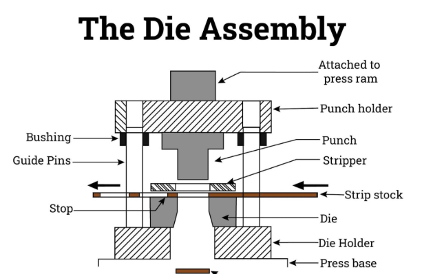
The punch-and-die relationship forms the heart of this process. Here's how it works:
- The punch (male component) applies downward force and shapes the material
- The die block (female component) provides the opposing cavity or cutting edge
- The stripper removes the formed part from the punch after each press cycle
- Guide pins and bushings ensure perfect alignment between the two die halves
What is dies in manufacturing terms? They're precision instruments capable of performing operations including cutting, bending, piercing, embossing, forming, drawing, stretching, coining, and extruding—all in fractions of a second.
Why Stamping Remains Manufacturing's Workhorse
So what is stamped metal's advantage over other fabrication methods? The answer comes down to speed, consistency, and economics at scale. Once a die is built, it can produce thousands—even millions—of identical parts with tolerances measured in thousandths of an inch.
Consider this: compound die stamping can achieve production rates exceeding 1,000 units per hour, according to IQS Directory. That efficiency makes stamping indispensable for industries ranging from automotive and aerospace to electronics and medical devices.
The relationship between the stamping process and its die tooling isn't just technical—it's economic. Every feature of the finished part, from its geometry to its surface finish, traces back to decisions made during die design. Understanding this connection is the first step toward mastering one of manufacturing's most versatile and powerful processes.
Essential Die Types Every Engineer Should Understand
Choosing the wrong die type for your project is like using a sledgehammer to hang a picture frame—technically possible, but expensive and inefficient. Understanding the types of stamping dies available helps you match your tooling investment to your production goals from day one. Let's explore the three major categories that manufacturers encounter most frequently and—more importantly—when each one makes sense for your application.
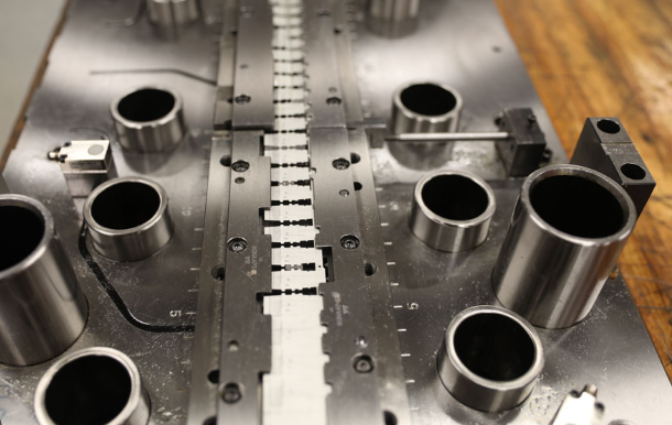
Progressive Dies and Their Multi-Station Advantage
Picture an assembly line compressed into a single tool. That's essentially what progressive stamping delivers. A metal coil feeds continuously through the pressing die, advancing through multiple stations where each stop performs a specific operation—blanking, piercing, forming, or bending—until the finished part separates at the final station.
According to Engineering Specialties Inc., the workpiece remains attached to the base strip from beginning to end, with separation being the final step. This approach offers several distinct advantages:
- High-speed production with minimal operator intervention
- Exceptional repeatability across millions of parts
- Reduced per-part costs at high volumes
- Complex geometries achieved through sequential operations
Automotive components progressive stamping represents one of the most demanding applications for this technology. Think of the intricate brackets, connectors, and structural reinforcements inside your vehicle—many of these parts emerge from progressive dies running at speeds exceeding 1,000 strokes per minute.
However, progressive dies do come with trade-offs. The initial tooling investment is substantial, and they're not ideal for parts requiring deep drawing operations where the metal must flow significantly beyond its original plane.
Transfer Dies for Complex Geometries
What happens when your part design demands operations that progressive stamping simply can't handle? Transfer stamping steps in to fill this gap. Unlike progressive dies where parts stay connected to the strip, transfer die stamping separates each blank immediately, then mechanical "fingers" transport individual pieces through successive stations.
This method shines for larger, more complex components. According to Worthy Hardware, transfer dies excel at producing parts with intricate design elements like knurls, ribs, and threading that would be impossible with other approaches.
Transfer dies unlock several capabilities that other types cannot match:
- Deep drawing operations—without the strip attached, the press can punch as deep as the material allows
- Flexible part orientation—each station can approach the workpiece from different angles
- Tube applications—cylindrical components that require forming around a mandrel
- Large part production—components too big for progressive die setups
The trade-off? Transfer stamping typically runs slower than progressive methods, and operational costs climb due to the complexity of setup and the precision required in die design. For intricate parts produced in moderate to high volumes, though, the flexibility often justifies these considerations.
Compound Dies for Single-Stroke Efficiency
Sometimes simplicity wins. Compound die stamping performs multiple cutting, punching, and blanking operations simultaneously in a single press stroke—no sequential stations, no part transfer between steps. When your part geometry allows it, this approach delivers remarkable efficiency.
According to JV Manufacturing, compound dies are commonly used for tasks requiring high-speed accuracy, such as producing parts for electronics or medical equipment where precision is paramount.
The sweet spot for compound dies includes:
- Flat parts with internal features—washers, gaskets, and similar components
- High-precision requirements—since all operations occur simultaneously, alignment is guaranteed
- Material efficiency—careful die design minimizes scrap
- Medium to high production volumes—where tooling costs amortize across sufficient quantities
The limitation? Compound dies struggle with complex three-dimensional geometries. If your part requires significant forming, bending, or drawing operations, you'll need to look elsewhere.
Choosing the Right Die Type for Your Application
Sounds complex? The decision framework becomes clearer when you evaluate your specific requirements systematically. The table below compares these three die types across the factors that matter most:
| Factor | Progressive Stamping | Transfer Die Stamping | Compound Die Stamping |
|---|---|---|---|
| Operation Complexity | Multiple sequential operations; part stays on strip | Multiple independent stations; part transferred between each | Multiple operations in single stroke |
| Part Complexity Capability | Complex geometries; limited deep drawing | Highest complexity; deep draws, tubes, intricate features | Simple to moderate; primarily flat parts |
| Production Volume Suitability | High volume (100,000+ parts ideal) | Moderate to high volume; flexible scaling | Medium to high volume |
| Typical Applications | Automotive brackets, electrical connectors, small stampings | Deep-drawn housings, large automotive panels, tube components | Washers, gaskets, electronic shields, flat precision parts |
| Per-Part Cost at Volume | Lowest at high volumes | Moderate; depends on complexity | Low for suitable geometries |
| Initial Tooling Investment | High | High to very high | Moderate to high |
| Setup Time | Moderate | Longer; especially for intricate parts | Shortest |
When evaluating transfer dies versus progressive options, ask yourself: Does my part require deep drawing or complex three-dimensional forming? If yes, transfer stamping likely offers the only viable path. For simpler geometries at extremely high volumes, progressive dies typically deliver the best economics.
Understanding these distinctions positions you to have informed conversations with tooling engineers and make strategic decisions about your manufacturing approach. But selecting the right die type is only part of the equation—knowing how the complete stamping process unfolds from raw material to finished component reveals where additional optimization opportunities exist.
The Complete Stamping Process From Start to Finish
You've selected your die type and understand the tooling fundamentals—now what actually happens when production begins? The metal stamping process follows a carefully orchestrated sequence that transforms raw coil stock into precision components, often in fractions of a second. Understanding this workflow reveals where efficiency gains hide and why certain design decisions matter more than others.
Whether you're running a progressive die stamping process at 1,000 strokes per minute or a transfer operation handling complex geometries, the fundamental stages remain consistent. Let's walk through the complete journey from raw material to finished part.
From Coil to Component in Sequential Steps
The manufacturing stamping process unfolds in a precise sequence where each step builds upon the previous one. Here's exactly what happens during a typical production run:
-
Material Preparation and Feeding
The stamping process begins with a heavy coil of metal strip mounted on an uncoiler. According to Jeelix, the coil passes through a straightener to remove internal stresses from coiling, ensuring a perfectly flat feed. A high-precision servo feeder then advances the strip toward the die at an engineer-defined pitch—accurate to the micron. This foundational step dictates the stability and accuracy of everything that follows. -
Pilot Hole Punching
Before any forming begins, the die punches two or more pilot holes in designated areas of the material. These holes aren't part of the final component—they serve as the "North Star" of the entire process. Every subsequent station uses these reference points for alignment, forming the bedrock that enables the progressive stamping process to achieve exceptional consistency. -
Blanking and Piercing Operations
As the strip advances step by step, piercing stations begin sculpting the material. Operations including piercing, trimming, and notching remove excess stock, establishing internal and external contours. At this stage, the part's two-dimensional profile emerges from the sheet metal stamping process. -
Forming Operations
This is where flat metal expands into the three-dimensional realm. Bending creates angles, drawing forms cavities, flanging builds edges, and embossing adds stiffening ribs or identification marks. The coining process applies additional pressure to achieve tight tolerances on critical dimensions—particularly useful when surface finish and dimensional accuracy are paramount. Each station performs only a small transformation, shaping the metal gradually to create complex geometries without tearing or excessive thinning. -
Precision Correction
In high-speed production, microscopic errors could theoretically accumulate over dozens of stations. To counter this, pilots mounted on the upper die enter previously punched locating holes with each stroke. As each tapered pin engages its hole, it generates lateral force that nudges the strip back into precise alignment—resetting the position and breaking any chain of accumulated error at its root. -
Secondary Operations
Depending on part requirements, additional in-die operations may include tapping, riveting, or basic component assembly. These "blank applied mass production techniques" eliminate downstream processes and reduce handling between stations. -
Final Cutting and Part Ejection
When the strip reaches the final station, a cut-off operation delivers the decisive stroke that separates the finished component from the carrier strip. The part is guided out via chutes, conveyors, or robotic arms while the skeletal scrap strip moves on for recycling.
Critical Checkpoints in the Stamping Workflow
Understanding the sequential steps is essential, but knowing where problems typically emerge separates experienced engineers from novices. Several critical checkpoints demand attention throughout the stamping process:
- Feed accuracy verification—Even minor misfeeds compound across stations. Servo feeders with closed-loop feedback systems detect and correct deviations before they cascade.
- Die alignment confirmation—Guide pins and bushings must maintain precise concentricity. Worn components introduce clearance variations that affect part quality.
- Lubrication monitoring—Proper lubricant application prevents galling, reduces die wear, and ensures consistent material flow during forming operations.
- Strip layout efficiency—The arrangement of parts on the strip directly impacts material utilization. Skilled die designers optimize layouts to minimize scrap while maintaining structural integrity of the carrier strip.
Material utilization deserves special attention. According to industry experts, raw materials typically account for 50% to 70% of a stamped part's cost. Strategic strip layout design—whether using solid carrier strips for simple parts or stretch webs for complex 3D forming—directly affects your bottom line.
Where Quality Control Intersects Each Stage
Quality isn't something you inspect into a product at the end of the line—it's built into every stroke of the metal stamping process. Effective quality control intersects multiple stages:
- Incoming material inspection—Verify coil thickness, hardness, and surface condition before production begins
- First-article verification—Comprehensive dimensional checks on initial parts confirm die setup accuracy
- In-process monitoring—Sensors detect abnormal press loads, misfeeds, or slug ejection failures in real time
- Statistical process control—Sampling protocols track dimensional trends and signal when adjustments are needed
- Final inspection—Automated vision systems or manual checks verify critical dimensions before packaging
The progressive die stamping process offers a particular advantage here: because all operations occur within a single die, part-to-part consistency remains extraordinarily tight. When tolerances of ±0.005 inches (±0.127 mm) are standard—and specialized equipment can achieve ±0.001 inches (±0.025 mm)—early detection of drift prevents scrap accumulation.
Now that you understand how the complete workflow unfolds, the next logical question becomes: what exactly are you looking at when you peer inside that precision-engineered die? The answer reveals why tooling quality matters so much to everything we've just discussed.
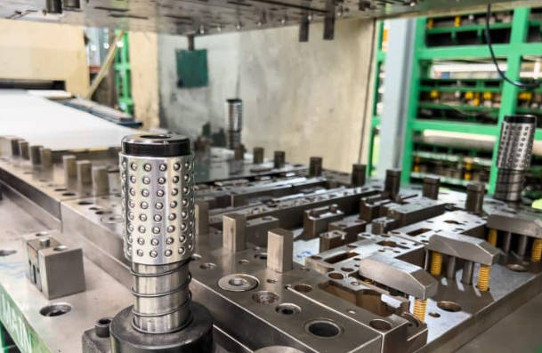
Inside the Die Assembly and Its Critical Components
When you examine a stamping die for the first time, it might look like a solid block of steel. Look closer, though, and you'll discover an intricate assembly where every component serves a precise function. Understanding these stamping die components transforms you from someone who simply uses tooling into someone who can evaluate specifications, troubleshoot problems, and communicate effectively with die makers. Let's open up the die and examine what's really inside.
A complete stamp die set consists of dozens of individual parts working in concert. Each component must maintain its position, withstand tremendous forces, and perform reliably through millions of cycles. Here are the essential elements you'll encounter in any professional stamping die design:
- Die shoes—The heavy base plates forming the upper and lower halves of the assembly; they mount to the press and hold all other components in precise alignment
- Punch plates—Hardened plates that secure and position the cutting or forming punches
- Die blocks—Female counterparts to punches containing the cavities or cutting edges that define part geometry
- Strippers—Plates that remove material from punches after each stroke, preventing parts from lifting with the upper die
- Pilots—Tapered pins that enter previously punched holes to align the strip precisely before each operation
- Guide pins and bushings—Precision-ground components ensuring perfect alignment between upper and lower die halves
- Springs—Provide controlled pressure for strippers, pressure pads, and part ejection systems
- Backing plates—Hardened plates behind punches and die buttons that distribute load and prevent deformation of softer die shoe material
Upper and Lower Die Shoe Architecture
Imagine the die shoes as the skeleton of your entire tool. These massive plates—often weighing hundreds of pounds—provide the rigid foundation that makes precision possible. According to U-Need, the lower die shoe mounts to the press bed or bolster, while the upper die shoe attaches to the press slide or ram.
The architecture of die stamps begins with material selection for these shoes. Most manufacturers use cast iron or steel alloys chosen for their combination of rigidity, machinability, and cost-effectiveness. Common options include:
- Gray cast iron (G2500, G3500)—Excellent vibration damping and machinability for general applications
- Pearlitic ductile iron (D4512, D6510)—Higher strength and toughness for demanding applications
- Cast steel (S0050A, S7140)—Maximum strength for high-tonnage operations
The shoe design must account for deflection under load. Even a few thousandths of an inch of flex can throw off part dimensions. Engineers calculate expected forces and specify shoe thickness accordingly—typically ranging from 2 to 6 inches depending on die size and press tonnage.
Punch and Matrix Precision Requirements
While die shoes provide the foundation, punches and die blocks do the actual work of shaping metal. These components endure the greatest stresses and require the tightest tolerances in the entire assembly.
The punch—the male component—must maintain its cutting edge or forming profile through millions of cycles. Die buttons (the female cutting components) require equally precise machining. The clearance between punch and die button determines edge quality on blanked or pierced parts. Too tight, and the die galls and wears prematurely. Too loose, and burrs form on part edges.
Metal stamping die design specifies this clearance as a percentage of material thickness—typically 5% to 12% per side for most steel alloys, though high-strength materials may require larger clearances. Getting this relationship right is fundamental to sheet metal die performance.
Material selection for punches and die blocks follows different criteria than for die shoes. Here's how common tool steel grades compare:
| Tool Steel Grade | Hardness (HRC) | Key Properties | Best Applications |
|---|---|---|---|
| D2 | 58-62 | High wear resistance, good toughness | General blanking and piercing |
| A2 | 57-62 | Balanced wear/toughness, air hardening | Forming operations, moderate wear |
| S7 | 54-58 | High shock resistance | Heavy blanking, impact applications |
| M2 (High Speed) | 60-65 | Maintains hardness at elevated temperatures | High-speed production, abrasive materials |
| Powder Metallurgy (PM) | 58-64 | Fine carbide distribution, superior toughness | Advanced high-strength steels, long runs |
| Tungsten Carbide | 70+ | Extreme wear resistance | Highest volume, abrasive materials |
According to AHSS Insights, when stamping advanced high-strength steels, conventional tool steels like D2 may fail after only 5,000-7,000 cycles compared to 50,000+ cycles with mild steel. Switching to powder metallurgy tool steels can restore expected tool life by providing the necessary combination of hardness and impact resistance.
The Critical Role of Pilots and Strippers
Pilots and strippers don't shape the metal directly, but without them, consistent production would be impossible. These components solve two fundamental challenges in stamping operations.
Pilots ensure positional accuracy. As the strip advances through a progressive die, cumulative positioning errors could throw off dimensions across subsequent stations. Pilots—precision-ground tapered pins mounted in the upper die—enter previously punched holes with each stroke. Their tapered shape generates lateral force that nudges the strip back into precise alignment, resetting position at every station.
Strippers ensure reliable part separation. When a punch pierces or blanks material, the sheet metal's elasticity causes it to grip the punch tightly. Without intervention, the material would lift with the punch on the upstroke, jamming the die. Stripper plates solve this by mechanically holding the material down as the punch withdraws. Spring-loaded strippers offer the added benefit of controlled pressure during forming operations.
Understanding Bypass Notches in Sheet Metal Stamping Dies
One specialized feature often overlooked in stamping die components is the bypass notch. What is the purpose of bypass notches in stamping dies? These carefully positioned cutouts in the die allow controlled material flow during forming operations.
When metal is drawn or formed, it must flow from one area to another. Bypass notches in sheet metal stamping dies create relief zones that permit this movement without excessive thinning or tearing. They also help balance pressures across complex part geometries, preventing wrinkles in some areas while ensuring adequate material stretch in others.
Die designers position these notches based on simulation analysis and experience. Their size, shape, and location directly affect part quality—too small, and material flow is restricted; too large, and you lose control over blank holding forces. For complex drawn parts, getting bypass notch design right can mean the difference between consistent production and chronic defect issues.
Understanding these critical components gives you the vocabulary to evaluate die specifications and communicate effectively with tooling suppliers. But even the best-designed die assembly is only as good as the materials you run through it—which brings us to the strategic decisions around material selection that can make or break your stamping operation.
Material Selection Strategies for Optimal Results
You've designed your die, mapped out your process, and understand every component in the tooling assembly—but run the wrong material through that press, and none of it matters. Material selection isn't just a procurement decision; it's a strategic choice that affects formability, tooling longevity, part performance, and ultimately your bottom line. Let's explore how to match materials to applications with the precision your stamped parts demand.
Matching Material Properties to Part Requirements
When evaluating materials for metal stamping and forming, five critical properties should drive your decision. According to QST Corporation, these factors directly affect final product quality, cost, and durability:
- Formability—How easily the material bends, stretches, and flows without cracking or tearing
- Strength—The material's ability to withstand applied loads in the finished application
- Thickness—Directly impacts press tonnage requirements and die clearance specifications
- Hardness—Affects tool wear, springback behavior, and surface finish quality
- Corrosion resistance—Critical for parts exposed to moisture, chemicals, or harsh environments
Here's the challenge: these properties often work against each other. A material with excellent strength typically sacrifices formability. High corrosion resistance may come with increased cost or reduced machinability. Understanding these trade-offs helps you select materials that deliver the right balance for your specific stamped parts.
The table below compares common stamping materials across these essential factors:
| Material | Formability | Strength | Relative Cost | Typical Applications |
|---|---|---|---|---|
| Carbon Steel (1008, 1010) | Excellent | Low to moderate | Low | Brackets, housings, structural components, automotive panels |
| Stainless Steel (304, 316) | Moderate | High | High | Medical devices, food equipment, marine applications |
| Aluminum (3003, 5052, 6061) | Good to excellent | Low to moderate | Moderate | Aerospace, electronics enclosures, heat sinks, lightweight automotive |
| Copper Alloys (C110, Brass, Bronze) | Excellent | Low to moderate | High | Electrical connectors, RF shielding, decorative hardware |
| High-Strength Low-Alloy (HSLA) | Moderate | Very high | Moderate to high | Automotive structural, safety components, load-bearing parts |
Steel Versus Aluminum Stamping Considerations
The steel-versus-aluminum decision appears in nearly every manufacturing conversation today, especially as lightweighting pressures intensify across automotive and aerospace sectors. Both materials work beautifully in stamping operations—but they demand different approaches.
Steel stamping dies benefit from the material's predictable behavior. Carbon steels like 1008 and 1010 offer exceptional formability, allowing complex geometries without specialized tooling modifications. Steel's higher modulus of elasticity means less springback to compensate for, and its work-hardening characteristics actually strengthen the material during forming.
The aluminum stamping process introduces different dynamics. Aluminum's lower density (roughly one-third of steel) delivers significant weight savings, but its softer nature requires careful attention to die clearances and surface finishes. According to Alekvs, aluminum's formability depends heavily on alloy and temper selection—annealed conditions form more easily, while hardened tempers sacrifice ductility for strength.
Key differences affecting die design include:
- Die clearances—Aluminum typically requires tighter punch-to-die clearances (5-8% of thickness) compared to steel (8-12%)
- Surface finish requirements—Aluminum galls more easily, demanding polished die surfaces and proper lubrication
- Springback compensation—Aluminum exhibits greater elastic recovery, requiring increased overbending in die design
- Press tonnage—Lower material strength means reduced force requirements, but higher speeds are possible
Specialty Alloys and Their Forming Challenges
Beyond standard materials, stamped sheet metal applications increasingly demand specialty alloys that push tooling to its limits. Advanced high-strength steels (AHSS), titanium alloys, and nickel superalloys each present unique forming challenges.
Material thickness and hardness directly affect die design requirements and press tonnage calculations. According to industry guidelines, tooling must withstand tremendous forces—thin materials don't automatically mean lower tonnage requirements when hardness increases significantly.
Springback represents one of the most frustrating challenges in metal stamped parts production. When material bends, the inner surface compresses while the outer surface stretches. Upon release, these competing stresses cause the material to partially return toward its original shape. Harder materials and tighter bend radii amplify this effect.
Effective die compensation strategies include:
- Overbending—Forming past the target angle so springback returns the part to specification
- Bottom coining—Applying additional pressure at the bend apex to set the material permanently
- Stretch forming—Inducing tension across the bend to minimize elastic recovery
- Material-specific adjustments—According to Dahlstrom Roll Form, springback predictions rely on understanding yield point and elastic modulus for each specific alloy
Getting material selection right from the start prevents costly mid-production changes and ensures your steel stamping dies or aluminum tooling performs as designed. But even with optimal materials, problems can emerge during production—which brings us to the troubleshooting knowledge that separates experienced engineers from those still climbing the learning curve.
Troubleshooting Common Stamping Defects and Solutions
Even the most precisely engineered die stamped parts can develop quality issues during production. The difference between struggling through chronic problems and resolving them quickly lies in understanding the relationship between symptoms and root causes. This troubleshooting guide transforms you from someone who reacts to defects into someone who diagnoses and eliminates them systematically.
When defects appear on your stamped components, resist the urge to make random adjustments. Each quality issue tells a story about what's happening inside your die processing operations—you just need to learn how to read the clues.
Diagnosing Burr Formation and Edge Quality Issues
Burrs rank among the most common complaints in precision die & stamping operations. These raised edges or material fragments compromise part function, create safety hazards, and add secondary deburring costs. According to industry experts, burrs typically appear when the punch-to-die clearance falls outside optimal range or when cutting edges have worn past their useful life.
Here's what burr characteristics reveal about your process:
- Uniform burrs around the entire perimeter—Clearance is likely too large; reduce gap toward the 8% of material thickness baseline
- Burrs on one side only—Die alignment has shifted; check guide pins, bushings, and die shoe parallelism
- Increasing burr height over time—Edge wear is progressing; schedule inspection and potential regrinding
- Torn or ragged edges—Clearance may be too tight, or lubrication is insufficient
As an example of stamping defect resolution, one manufacturer experiencing persistent burrs on copper terminals switched to zero-gap blanking technology and eliminated the issue entirely. The solution required understanding that conventional clearances weren't appropriate for that specific material and geometry.
Solving Dimensional Accuracy Problems
When parts drift out of tolerance, the investigation begins with understanding where in the process variation enters. Dimensional issues in metal stamping techniques typically trace back to three categories: tooling condition, material variation, or process parameters.
According to HLC Metal Parts, actual dimensions may deviate from design drawings due to excessive mold production wear, inaccurate positioning, material rebound, or insufficient press rigidity. Each cause demands a different corrective approach.
Springback deserves special attention because it affects nearly every formed part. When material bends, internal stresses cause partial recovery toward the original flat state. Harder materials and tighter radii amplify this effect. Solutions include overbending compensation in die design, adding bottom coining pressure, or implementing CAE simulation to predict and offset springback during the tooling development phase.
Preventing Material Cracking and Splitting
Cracks represent catastrophic failure—unlike burrs or dimensional drift, cracked parts cannot be salvaged. Prevention requires understanding the forming limits of your specific material and designing operations that stay within those boundaries.
Cracking typically occurs in localized areas where high strains or stresses concentrate. According to manufacturing research, common triggers include insufficient material ductility, excessive drawing ratios, improper blank holder pressure, and die radii that are too small for the material thickness.
Practical prevention strategies include:
- Verify die corner radii meet the R≥4t guideline (where t equals material thickness)
- Implement stepped drawing operations—60% initial draw, then secondary shaping
- Consider intermediate annealing for deep-draw applications
- Use hot forming (200-400°C) for advanced high-strength steels that resist cold forming
Complete Defect Diagnosis Reference
The following table maps common defects to their root causes and proven corrective actions—use it as your quick reference when production issues arise:
| Defect | Root Causes | Corrective Actions |
|---|---|---|
| Burrs | Excessive punch-die clearance; worn cutting edges; improper clearance for material type | Adjust clearance to 8-12% of thickness; regrind or replace worn edges; verify clearance specifications for specific alloy |
| Wrinkles | Insufficient blank holder force; excessive material in compression zones; improper draw bead design | Increase blank holder pressure; optimize blank size; add or adjust draw beads; consider servo hydraulic pad control |
| Cracks/Splits | Material ductility exceeded; drawing ratio too aggressive; die radii too small; insufficient lubrication | Reduce single-operation severity; increase die radii; add intermediate annealing; improve lubrication; consider material substitution |
| Springback | Elastic recovery inherent to material; insufficient forming pressure; improper bend compensation | Implement overbend compensation; add bottom coining; use CAE simulation for prediction; consider stretch forming |
| Surface Scratches | Die surface roughness; debris between die surfaces; coating adhesion failure; inadequate lubrication | Polish die surfaces to Ra0.2μm or finer; implement cleaning protocols; apply chrome or TD treatment; use appropriate stamping oil |
| Uneven Thickness | Material flow restrictions; excessive friction in draw operations; improper draw bead balance | Optimize draw bead layout; apply localized high-viscosity lubricant; increase die radii; consider more ductile material grade |
Reading Die Wear Patterns for Predictive Maintenance
Your dies communicate their condition through wear patterns—if you know how to interpret them. According to tooling experts, dies wear in patterns that mirror how your process runs, making wear analysis a powerful diagnostic tool.
Key patterns and their meanings include:
- Asymmetrical wear bands—Indicates alignment problems; check tool stack parallelism and die shoe squareness
- Localized galling or metal pickup—Points to adhesive wear from high contact pressure, poor material pairing, or weak lubrication
- Polished or burnished zones—Signals sustained sliding, often from under-clamping or excessively smooth die finish
- Edge chipping or micro-cracks—Surface is too hard and brittle, or EDM recast layer wasn't properly removed
The critical question becomes: when should you regrind versus replace? Regrinding makes sense when the die geometry can be restored within print tolerances and sufficient case depth or coating remains. According to maintenance guidelines, replacement becomes necessary when dies show cracking, spalling, hardness loss, out-of-round grooves, radius changes beyond tolerance, or persistent galling that regrinding won't correct.
Establish inspection intervals based on your specific production—many operations check cutting edges every 50,000 strokes. Track wear progression with photos and measurements to predict when intervention is needed before defects appear in production.
The Role of Lubrication in Defect Prevention
Proper lubrication serves as your first line of defense against multiple defect categories. It reduces friction during stamping and die cutting operations, prevents galling on susceptible materials like aluminum and stainless steel, extends die life, and improves surface finish on formed parts.
Lubrication selection must match your material and application:
- Volatile stamping oils—Evaporate after forming, eliminating cleaning operations
- High-viscosity lubricants (graphite paste)—Apply locally for severe draw operations
- Non-staining formulations—Essential for aluminum and decorative applications
- MQL (minimum quantity lubrication)—Provides tighter control for precision operations
According to process research, high cycle rates without lubricant refresh build frictional heat and degrade lubricant films, accelerating adhesive wear on galling-prone materials. Schedule brief lubrication refresh intervals during extended production runs, especially when processing stainless steel, thick sections, or abrasive materials.
Mastering troubleshooting transforms reactive firefighting into proactive process control. But the most sophisticated problem-solving still relies on fundamental technology—and today's stamping operations increasingly leverage advanced capabilities that were unimaginable just a decade ago.
Modern Technology Transforming Stamping Operations
Remember when die development meant building physical prototypes, running trials, and hoping for the best? Those days are rapidly disappearing. Today's die stamping machine operations leverage sophisticated digital tools that predict problems before they occur, adapt in real time to material variations, and generate actionable insights from every press stroke. Understanding these technologies separates manufacturers who compete on efficiency from those left behind.
CAE Simulation in Modern Die Development
Computer-aided engineering has revolutionized how stamping tooling moves from concept to production. Instead of discovering forming issues during costly physical tryouts, engineers now simulate the entire stamping process virtually—predicting material flow, identifying potential cracks, and optimizing die geometry before cutting a single piece of steel.
According to Keysight, simulation tools analyze how sheet metal behaves under the complex forces of blanking, forming, and drawing operations. These digital models account for material properties, friction coefficients, press characteristics, and tooling geometry to predict outcomes with remarkable accuracy.
What does this mean practically? Consider these advantages:
- Reduced development cycles—Virtual iteration replaces physical trial-and-error, cutting weeks or months from project timelines
- First-pass success rates—Simulation-validated dies frequently achieve acceptable parts on initial tryout
- Material utilization optimization—Engineers test multiple blank layouts digitally to minimize scrap
- Springback prediction—Software calculates elastic recovery and recommends compensation strategies before tooling is built
For technical stamping applications involving advanced high-strength steels or complex geometries, CAE simulation has become essential rather than optional. These materials behave unpredictably under traditional rules-of-thumb, making virtual validation critical for automotive stamping die development and similar demanding applications.
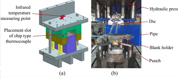
Servo Press Technology and Process Control
Traditional mechanical presses operate with fixed stroke profiles—the ram follows the same motion path regardless of what you're forming. Servo presses shatter this limitation. By replacing mechanical flywheels with programmable servo motors, these die-stamping machine systems offer unprecedented control over ram motion throughout every stroke.
According to ATD, servo presses provide programmability and variable stroke speeds that give manufacturers greater control over material flow, bend angles, and forming forces. This flexibility allows precise creation of intricate shapes while minimizing defects like wrinkling, tearing, or springback.
Why does this matter for your metal stamping tooling operations?
- Customizable motion profiles—Slow approach speeds for material contact, rapid return strokes for productivity, dwelling at bottom dead center for coining operations
- Material-sensitive forming—Aluminum, high-strength steel, and other challenging materials benefit from optimized velocity curves
- Reduced die wear—Controlled contact velocities minimize impact loads on cutting edges
- Energy efficiency—Power consumed only when needed, unlike constantly running flywheel systems
- Quieter operation—Lower impact speeds mean reduced noise levels in manufacturing environments
According to industry sources, servo presses are increasingly popular for their precision and flexibility, particularly in forming high-strength steel or aluminum where traditional press dynamics create quality challenges.
Industry 4.0 Integration in Stamping Operations
Imagine your stamping tooling talking to you—reporting its own health, predicting when maintenance is needed, and automatically adjusting parameters to maintain quality. That's the promise of Industry 4.0 integration, and leading manufacturers are already realizing these benefits.
Sensor integration transforms every die stamping machine into a data-generating asset. Load cells monitor tonnage throughout each stroke, detecting subtle changes that indicate die wear or material variation. Proximity sensors verify strip positioning. Temperature sensors track die heating that affects clearances and lubrication effectiveness.
This sensor data feeds analytical systems that deliver actionable intelligence:
- Real-time quality monitoring—Abnormal force signatures trigger alerts before defective parts accumulate
- Predictive maintenance—Algorithms identify wear trends and schedule intervention before failures occur
- Process optimization—Historical data reveals correlations between parameters and outcomes, guiding continuous improvement
- Traceability—Complete production records link every part to its specific processing conditions
The integration extends beyond individual presses. Connected systems share data across production lines, enabling enterprise-wide visibility into stamping operations. Quality trends, equipment utilization, and maintenance needs become visible to decision-makers in real time rather than buried in spreadsheets discovered weeks later.
For manufacturers producing safety-critical components—where every part must meet specification—this level of process visibility and control represents a fundamental capability rather than a nice-to-have feature. The technology exists today; the question is whether your operation leverages it effectively.
These technological advances deliver impressive capabilities, but they also affect project economics in ways that deserve careful analysis. Understanding how development costs, production volumes, and technology investments interact helps you make informed decisions about where to invest your tooling dollars.
Cost Analysis and ROI for Die Investment Decisions
You've mastered die types, understand the process, and can troubleshoot defects with confidence—but here's the question that keeps engineers and buyers awake at night: Is this tooling investment actually worth it? Surprisingly, most resources on stamping manufacturing skip the financial analysis entirely, leaving you to guess whether your project economics make sense. Let's fix that by building the decision framework you actually need.
Calculating True Die Investment Costs
When evaluating stamping die manufacturing projects, the sticker price on the tooling quote represents only the beginning of your total investment. According to The Fabricator, numerous factors beyond basic construction costs affect the final number—and understanding them prevents budget surprises down the road.
Here's what actually drives your total cost of ownership in dies manufacturing:
- Initial die construction—Design engineering, material procurement, CNC machining, heat treatment, assembly, and tryout. Complex progressive dies can range from $50,000 to over $500,000 depending on size and sophistication.
- Material costs—Raw stock represents 50-70% of finished part cost according to Die-Matic. Material selection directly impacts both tooling requirements and ongoing production economics.
- Maintenance and regrinding—Cutting edges require periodic sharpening. Budget for inspection intervals, grinding cycles, and eventual component replacement based on expected production volumes.
- Press time—Hourly rates for press capacity, setup time between runs, and any dedicated equipment requirements affect production costs significantly.
- Secondary operations—Deburring, cleaning, plating, heat treating, or assembly steps add cost and handling between operations.
- Quality inspection—First-article approval, in-process sampling, final inspection protocols, and any specialized measurement requirements contribute to per-part costs.
Die complexity directly correlates with both cost and lead time. According to industry sources, progressive dies typically cost more than single-station dies because they require strip carrier design, station sequencing, and precision lifter timing. High-volume applications may justify premium tooling materials like solid carbide, which demands wire EDM machining and diamond finishing—adding significant cost but extending die life dramatically.
Volume Thresholds That Justify Tooling Investment
Here's the fundamental truth about metal stamping manufacturing economics: upfront tooling costs are high, but per-part costs drop dramatically as volume increases. Understanding where your project falls on this curve determines whether stamping makes financial sense.
According to Mursix, custom die creation represents the most significant upfront expense, but once the die is made, the per-unit cost decreases significantly with higher production runs. This creates a crossover point where stamping becomes more economical than alternative methods.
Consider this simplified example:
| Production Volume | Tooling Cost Per Part | Production Cost Per Part | Total Per-Part Cost |
|---|---|---|---|
| 1,000 parts | $50.00 | $0.25 | $50.25 |
| 10,000 parts | $5.00 | $0.25 | $5.25 |
| 100,000 parts | $0.50 | $0.25 | $0.75 |
| 1,000,000 parts | $0.05 | $0.25 | $0.30 |
This simplified model illustrates why stamping dominates high-volume production. At 1,000 parts, your tooling investment overwhelms production economics. At 1,000,000 parts, tooling becomes nearly irrelevant to per-part cost. The exact crossover point where stamping beats alternatives like laser cutting or CNC machining depends on part geometry, material, and tolerance requirements—but it typically falls somewhere between 5,000 and 50,000 parts for most applications.
Hidden Costs That Impact Total Project Economics
Beyond the obvious line items, several hidden factors can dramatically affect your manufacturing die investment returns. Experienced engineers account for these variables before committing to tooling expenditures.
Lead time and expediting costs: According to tooling experts, a request for very short delivery time on the tool most likely will inflate tooling cost. Shops working overtime or prioritizing your project over existing commitments charge premium rates. Standard lead times for complex progressive dies range from 12 to 20 weeks—rushing that timeline adds 20-50% to costs.
Design iteration cycles: Every revision to part geometry after die construction begins triggers rework costs. Investing in thorough design-for-manufacturability analysis upfront prevents expensive modifications later. According to Die-Matic, early prototyping in the design phase helps identify potential issues before mass production, avoiding costly redesigns and tooling adjustments.
First-pass approval rates: What happens when initial tryout parts don't meet specification? You face additional engineering time, die modifications, and repeat tryouts—each cycle adding cost and delays. This is where working with experienced metal stamping die manufacturers pays dividends. Suppliers with advanced CAE simulation capabilities can reduce development risk significantly. For example, IATF 16949-certified suppliers like Shaoyi achieve 93% first-pass approval rates through simulation-validated tooling design, dramatically reducing the hidden costs of development iterations.
Geographic considerations: Labor rate differences between regions affect tooling costs substantially. According to The Fabricator, countries with lower labor rates typically offer lower tooling costs, though this must be balanced against communication challenges, shipping logistics, and intellectual property concerns.
Making the Investment Decision
Armed with this cost framework, how do you decide whether to proceed with stamping tooling? Start by calculating your break-even volume:
Break-even Volume = Total Tooling Investment ÷ (Alternative Per-Part Cost - Stamping Per-Part Cost)
If your projected production exceeds this break-even point with comfortable margin, stamping likely makes sense. If you're borderline, consider these questions:
- Is this a recurring annual requirement, or a one-time production run?
- Are design changes likely, or is the part geometry locked?
- Does the application demand tolerances or volumes that only stamping can deliver?
- Can you prototype economically before committing to production tooling?
On that last point, rapid prototyping options have transformed project timelines. Modern custom metal stamping die suppliers can deliver prototype tooling in as little as 5 days for simple geometries, allowing you to validate designs before committing to full production tooling. This approach—available through specialized providers like Shaoyi—reduces development risk while compressing overall project schedules.
The economic analysis tools covered here give you the framework to evaluate stamping investments objectively. But stamping isn't the only option—and understanding how it compares to alternative manufacturing methods ensures you're choosing the right process for your specific requirements.
Stamping Versus Alternative Manufacturing Methods
You've run the numbers on die investment and understand the economics—but here's the question that trips up even experienced engineers: Is stamping actually the right process for this part? The answer isn't always obvious. Laser cutting, CNC machining, and waterjet cutting each offer compelling advantages for specific applications. Understanding where die stamping excels—and where alternatives make more sense—ensures you're choosing the optimal manufacturing path rather than defaulting to familiar territory.
When Stamping Outperforms Laser Cutting
Laser cutting has revolutionized prototyping and low-volume production with its flexibility and zero-tooling startup costs. But when volumes climb, the economics shift dramatically in favor of sheet metal stamping.
Consider the fundamental difference: laser cutting processes one part at a time, tracing each contour with a focused beam. Metal stamping dies produce complete parts in fractions of a second—often exceeding 1,000 strokes per minute for progressive operations. According to DureX Inc., once your tooling is set, stamping can run continuously to meet demanding schedules and tight deadlines.
Where does stamping metal parts pull ahead of laser cutting?
- Volume threshold—Beyond approximately 5,000-10,000 parts, stamping's per-piece cost typically drops below laser cutting despite tooling amortization
- Three-dimensional forming—Laser cutting produces flat profiles only; stamping dies create bends, draws, and complex 3D geometries in a single operation
- Edge quality—Properly maintained metal stamping dies produce clean, burr-free edges without the heat-affected zone that laser cutting leaves behind
- Material efficiency—Progressive die layouts optimize strip utilization, often achieving better material yield than nested laser patterns
- Cycle time—A part requiring 45 seconds of laser cutting time emerges from a stamping die in under one second
However, laser cutting maintains clear advantages for prototyping, design iteration, and applications where tooling investment cannot be justified. The key is recognizing the crossover point for your specific production requirements.
CNC Machining Versus Die Stamping Trade-offs
CNC machining and stamping represent fundamentally different approaches to metalworking. Machining removes material from solid blocks or blanks through subtractive processes. Stamping forms sheet metal through controlled deformation. Each approach excels in different scenarios.
According to industry experts, CNC machining offers extremely high precision ideal for tight tolerances and complex geometries, while metal stamping remains cost-effective for high-volume production of simpler forms. Understanding when each method shines helps you match the process to your application.
CNC machining wins when you need:
- Exceptional precision—Tolerances below ±0.001 inches that even precision sheet metal stamping dies cannot consistently achieve
- Complex 3D geometries from solid—Parts requiring features machined from multiple angles or internal cavities
- Thick, hard materials—Stock exceeding typical sheet metal thicknesses or hardnesses unsuitable for forming
- Frequent design changes—Reprogramming a CNC machine costs nothing compared to modifying or rebuilding stamping dies
- Low volumes—According to Hubs, CNC is typically used for low- to medium-volume production where tooling investment cannot be justified
Die stamping wins when you need:
- High-volume consistency—Producing thousands or millions of identical metal parts stamping operations at speeds CNC cannot match
- Thin material forming—Sheet metal applications where machining from solid would waste 90%+ of raw material
- Lower per-part costs at scale—Once tooling is amortized, stamping delivers dramatically lower unit economics
- Integrated operations—Progressive automotive stamping dies perform blanking, piercing, forming, and trimming in a single press stroke
According to DureX, CNC machining may have a higher cost per unit for large volumes due to equipment complexity and setup, but it offers unique advantages in flexibility and precision that stamping cannot replicate.
Complete Manufacturing Method Comparison
The following table provides a comprehensive comparison across the manufacturing methods you're most likely evaluating:
| Factor | Die Stamping | Laser Cutting | CNC Machining | Waterjet Cutting |
|---|---|---|---|---|
| Volume Suitability | High volume (10,000+ ideal) | Low to medium (1-5,000) | Low to medium (1-1,000 typical) | Low to medium (1-5,000) |
| Per-Part Cost at 100 Parts | Very high (tooling dominates) | Moderate | Moderate to high | Moderate |
| Per-Part Cost at 100,000 Parts | Very low | High (cycle time limited) | Very high (not practical) | Very high (not practical) |
| Geometric Complexity | 3D forming, draws, complex shapes | 2D profiles only | Highest—any machinable geometry | 2D profiles, some beveling |
| Material Thickness Range | 0.005" to 0.250" typical | Up to 1"+ depending on material | Virtually unlimited | Up to 12"+ for some materials |
| Surface Finish Quality | Good to excellent | Good (heat-affected zone present) | Excellent (controllable) | Moderate (may require finishing) |
| Tooling Investment | $10,000 to $500,000+ | None (programming only) | Minimal (fixtures, tooling) | None (programming only) |
| Lead Time to First Part | 8-20 weeks (tooling dependent) | Days | Days to weeks | Days |
| Design Change Flexibility | Low (requires die modification) | High (reprogram only) | High (reprogram only) | High (reprogram only) |
Hybrid Approaches for Optimal Results
Here's what experienced manufacturing engineers know: the best solution often combines multiple methods rather than committing exclusively to one. Hybrid approaches leverage the strengths of each process while minimizing their weaknesses.
Common hybrid strategies include:
Stamped blanks with secondary CNC operations: Use stamping dies to produce high-volume blanks with formed features, then add precision-machined holes, threads, or critical surfaces via CNC. This approach captures stamping's volume economics while achieving machining-level tolerances where they actually matter.
Laser-cut prototypes, stamped production: Validate designs with quick-turn laser-cut samples before investing in production tooling. Once geometry is locked, transition to stamping for volume production. According to DureX, this strategy helps clients avoid heavy upfront tooling investments when volumes are low and supports seamless transition to high-volume stamping when the time is right.
Progressive stamping with in-die tapping or assembly: Modern progressive dies can incorporate secondary operations like thread forming, fastener insertion, or component assembly—eliminating downstream handling entirely.
For high-volume automotive applications where stamping truly excels, specialized suppliers deliver comprehensive solutions that maximize these advantages. For example, Shaoyi offers OEM-standard tooling with complete mold design and fabrication capabilities—from rapid prototyping in as little as 5 days to high-volume manufacturing. This integrated approach demonstrates stamping's advantages for automotive production where quality, consistency, and volume economics converge.
Making Your Process Selection Decision
Sounds complex? The decision framework becomes clearer when you ask the right questions in sequence:
- What's your total lifetime volume? Below 5,000 parts, stamping rarely makes economic sense. Above 50,000, it almost always wins.
- Does your part require 3D forming? Bends, draws, and formed features require stamping or press brake operations—laser and waterjet produce flat profiles only.
- What tolerances are truly critical? If only specific features require tight tolerances, consider stamping the bulk geometry and machining critical surfaces.
- Is the design locked? Uncertain designs favor flexible processes; stable designs justify tooling investment.
- What's your timeline? Urgent prototypes demand laser or CNC; production ramp-ups allow time for die construction.
Understanding these trade-offs transforms process selection from guesswork into strategic decision-making. Whether you're stamping metal parts by the millions or evaluating whether tooling investment makes sense for a new program, the framework covered in this guide gives you the analytical tools to choose wisely—and the technical foundation to execute successfully once you do.
Frequently Asked Questions About Stamping and Die Manufacturing
1. What is the difference between die cut and stamping?
Die cutting typically refers to using shaped blades to cut flat materials like paper, cardboard, or thin plastics, while metal stamping uses precision dies under high pressure to both cut and form sheet metal into three-dimensional shapes. Stamping performs multiple operations including blanking, piercing, bending, drawing, and coining in a single press stroke, making it ideal for high-volume production of complex metal components. Die cutting remains a simpler process focused primarily on cutting flat profiles.
2. What is the difference between die casting and stamping?
Die casting and stamping are fundamentally different metal forming processes. Die casting melts metal and injects it into molds to create complex 3D parts, requiring high temperatures and specialized equipment. Stamping is a cold forming process that shapes sheet metal at room temperature using precision dies and press force. Stamping excels at producing thin-walled components at extremely high speeds, while die casting creates thicker, more intricate castings. Stamping typically offers lower per-part costs at high volumes and faster cycle times.
3. How much does a metal stamping die cost?
Metal stamping die costs vary significantly based on complexity, ranging from $10,000 for simple compound dies to over $500,000 for sophisticated progressive automotive dies. Key cost factors include die size, number of stations, material specifications, tolerance requirements, and production volume expectations. While upfront tooling investment is substantial, per-part costs decrease dramatically at high volumes. Working with IATF 16949-certified suppliers like Shaoyi, who achieve 93% first-pass approval rates through CAE simulation, can reduce overall project costs by minimizing development iterations and rework.
4. What are the main types of stamping dies and when should each be used?
The three primary stamping die types serve different applications. Progressive dies are ideal for high-volume production of complex parts, processing metal strips through multiple stations in sequence. Transfer dies handle larger components requiring deep draws and intricate geometries where parts must be transferred between stations. Compound dies perform multiple cutting operations in a single stroke, best suited for flat precision parts like washers and gaskets. Selection depends on part complexity, production volume, and geometric requirements.
5. What causes common stamping defects and how can they be prevented?
Common stamping defects stem from specific root causes with proven solutions. Burrs typically result from excessive punch-die clearance or worn cutting edges—addressed by adjusting clearance to 8-12% of material thickness and timely regrinding. Cracks occur when forming limits are exceeded, requiring larger die radii and stepped drawing operations. Springback is inherent to all bent materials but can be compensated through overbending and CAE simulation during die design. Proper lubrication, regular die maintenance, and process monitoring prevent most quality issues.