 Small batches, high standards. Our rapid prototyping service makes validation faster and easier —

Sheet Metal Forming Bending Defects? Fix Them Before They Cost You
Understanding Sheet Metal Forming and Bending Fundamentals
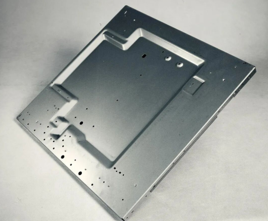
Ever looked at a car door panel, an HVAC duct, or even a simple mounting bracket and wondered how it got that shape? The answer lies in sheet metal forming bending—a cornerstone process that transforms flat metal sheets into the functional three-dimensional components we rely on every day. Before diving into the technical details of defect prevention, you need a solid grasp of what this process actually involves and why it matters.
From Flat Stock to Functional Parts
At its core, sheet metal bending involves applying controlled force to deform a flat metal sheet along a straight axis. Unlike cutting or stamping, which remove or punch out material, bending reshapes the metal without altering its surface integrity. This preservation of material strength makes it invaluable across manufacturing sectors.
When you're forming metal sheet into a bracket, enclosure, or structural component, you're essentially creating permanent deformation. The metal stretches on the outer surface of the bend and compresses on the inner surface. Understanding this fundamental behavior is crucial because it directly influences how you design parts and anticipate potential defects.
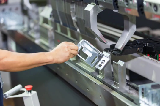
So, what is bending in practical terms? It's the controlled manipulation of sheet metal using tools like press brakes, folding machines, or roll benders to achieve specific angles and curves. The meaning of bending extends beyond simple angular changes—it encompasses the entire transformation from two-dimensional blank to three-dimensional component.
Why Bending Dominates Metal Fabrication
Bending sheet metal remains the go-to method for countless applications because it offers unmatched versatility and cost-effectiveness. Consider these key advantages:
- Material efficiency: Unlike machining, bending produces minimal waste since you're reshaping rather than removing material
- Structural integrity: Bent parts maintain consistent material properties throughout, with no welds or joints to weaken the structure
- Speed and repeatability: Modern CNC press brakes can produce identical bends across thousands of parts with remarkable precision
- Design flexibility: From simple 90-degree angles to complex multi-bend assemblies, the process accommodates diverse geometries
Industries from automotive to aerospace, consumer electronics to construction, depend on metal bending for everything from chassis components to aircraft fuselage sections. This widespread adoption stems from the process's ability to deliver precise, repeatable results at scale.
The Physics Behind Permanent Deformation
When you apply bending force to sheet metal, you're working with fundamental material properties. The metal deforms elastically at first—meaning it would spring back if released. Push beyond the material's yield strength, and you enter plastic deformation territory where the shape change becomes permanent.
Here's where things get interesting. The neutral axis—an imaginary line running through the material thickness where no stretching or compression occurs—shifts position during bending. This shift affects critical calculations like bend allowance and determines how much material you need in your flat pattern to achieve the final dimensions.
Springback, the tendency of metal to partially return toward its original shape after bending, represents one of the most significant challenges in achieving dimensional accuracy. Different materials exhibit varying degrees of springback, and compensating for it requires understanding the specific alloy's properties and the bending method employed.
With these foundational concepts established, you're ready to explore the specific bending methods, material considerations, and troubleshooting strategies that separate successful projects from costly failures.
Comparing Air Bending Bottoming and Coining Methods
Choosing the right bending process can make or break your project. Each method offers distinct trade-offs between precision, force requirements, and flexibility—and understanding these differences helps you avoid costly rework. Let's break down the three primary techniques that account for the vast majority of sheet metal bending operations.
Air Bending for Flexible Production
Air bending sheet metal represents the most versatile approach in modern fabrication. During this bending process, the workpiece contacts the tooling at only three points: two on the die shoulders and one at the punch tip. The metal never fully touches the die's inner surface, which is exactly where the name comes from.
What makes air forming so popular? You can achieve multiple bend angles using a single set of tools. Imagine having a 90 degree bending die—with air bending, you can produce any angle between 90 and 180 degrees simply by controlling punch depth. This flexibility translates directly to reduced tooling costs and faster setup times.
The force requirements are notably lower compared to other methods. According to industry data, air bending typically requires significantly less tonnage than bottoming or coining for the same material thickness. This means you can work with thicker materials on the same equipment, or use smaller presses for standard work.
However, air bending comes with a trade-off: springback compensation becomes more challenging. Since the metal isn't fully constrained during forming, predicting the exact final angle requires experience and often high-tech press brake controls that can make real-time adjustments.
Bottoming When Precision Matters
Bottoming—also called bottom pressing or bottom striking—emerged as the first practical alternative to coining. The punch presses the metal sheet onto the die's surface, forcing the material to conform more closely to the tooling geometry.
Here's how die bending through bottoming differs from air bending: the punch tip presses the sheet metal against the bottom of the V-die, causing controlled flexing. This contact creates a smaller internal bend radius and significantly reduces springback. The die's angle directly determines your final workpiece angle, making results more predictable.
The inner radius in bottoming follows a practical rule: it typically equals about 1/6 of the V-die opening width. So if you're using a 12mm die opening, expect an inside radius around 2mm. This relationship gives you design predictability that air bending can't always match.
The downside? Bottoming demands higher tonnage than air bending—though still considerably less than coining. This limits how thick you can go before exceeding your press brake's capacity. Most shops find bottoming works best for standard 90 degree bending applications where consistency matters more than flexibility.
Coining for Zero-Tolerance Applications
Coining takes precision to another level entirely. The name comes from currency manufacturing, where every coin must be identical to distinguish real money from counterfeits. In bending applications, coining delivers similarly exacting results.
The process involves the punch penetrating into the sheet metal, pressing a dent into the workpiece while forcing it against the die. This penetration, combined with forces 5-8 times higher than air bending, eliminates virtually all springback. When you need a 45-degree angle, you use a 45-degree punch and die—what you tool is what you get.
Coining excels at creating sharp, precisely defined bends with minimal inside radius. It's particularly suitable for forming accurate 90 degree bending on thin sheet metal where appearance and dimensional accuracy are paramount.
The limitations are significant, though. The extreme tonnage requirements typically restrict coining to thinner materials—usually under 1.5mm thickness. You also need dedicated tooling for each desired angle, eliminating the flexibility that makes air bending attractive for job shops.
Method Comparison at a Glance
This comparison table helps you match the right bending process to your specific requirements:
| Criteria | Air Bending | Bottoming | Coining |
|---|---|---|---|
| Force Requirements | Lowest (baseline) | Moderate (higher than air bending) | Highest (5-8x air bending) |
| Angle Accuracy | ±0.5° to ±1° typical | ±0.25° to ±0.5° typical | ±0.1° or better |
| Tooling Wear | Low—minimal contact | Moderate—full die contact | High—penetration causes wear |
| Springback Compensation | Requires overbending or CNC control | Reduced—controlled flexing helps | Virtually eliminated |
| Tooling Flexibility | High—multiple angles per tool set | Low—angle matches die geometry | None—dedicated tools required |
| Ideal Applications | Job shops, prototypes, varied production | Production runs requiring consistency | Thin materials, precision components |
| Thickness Range | Widest range possible | Limited by tonnage capacity | Typically under 1.5mm |
Secondary Methods Worth Knowing
Beyond the big three, two additional techniques handle specialized applications:
Rotary bending uses rotating dies to form angles—even sharper than 90 degrees—without scratching the material surface. This makes it ideal for pre-finished or coated materials where appearance matters. The method also accommodates U-channels with closely spaced flanges that would challenge other approaches.
Roll bending creates curves and cylinders using three adjustable rolls. When you need large-radius bends for applications like conical hoppers or curved architectural panels, roll bending delivers what straight-line methods cannot.
Understanding these method differences positions you to select the optimal approach for your material thickness, tolerance requirements, and production volume—factors that directly influence which defects you'll need to watch for when we examine material-specific guidelines next.
Material Selection and Thickness Guidelines for Bending
Ever tried bending stainless steel the same way you'd bend mild steel, only to watch your part crack at the bend line? Material selection isn't just about strength requirements—it fundamentally determines how your bending process will perform. Each metal brings unique characteristics that directly impact minimum bend radius, springback behavior, and your likelihood of producing defect-free parts.
Steel and Stainless Steel Bending Characteristics
Mild steel remains the workhorse of sheet metal fabrication for good reason. Its moderate strength and excellent ductility make it forgiving during bending operations. You'll find that mild steel accepts tighter bend radii without cracking and exhibits relatively predictable springback—typically on the lower end of the spectrum.
Bending stainless steel presents a different challenge entirely. According to engineering research, stainless steel's high strength translates directly to high springback, requiring more aggressive overbending compensation. The material also work-hardens rapidly during forming, which can lead to cracking if you're attempting tight radii without proper preparation.
Here's a practical consideration: stainless steel typically requires a minimum bend radius of 0.5 to 1.0 times the material thickness for soft tempers, but this increases significantly for work-hardened conditions. Compare this to mild steel, which often tolerates radii as tight as 0.5 times thickness across most temper states.
Aluminum Alloy Considerations
When bending aluminum sheet, the alloy designation matters as much as the metal itself. Not all aluminum behaves the same way under bending stress, and choosing the wrong alloy can turn a straightforward job into a cracking nightmare.
The 3003 series represents your best option for general-purpose bending aluminum sheets. With high ductility and excellent formability, it accepts tight radii and forgives minor process variations. If you're wondering how to bend aluminum sheet without cracking, starting with 3003-O (annealed) temper gives you the most margin for error.
The 5052 series offers a stronger alternative while maintaining good bendability. As noted by aluminum fabrication specialists, 5052 provides excellent fatigue strength and retains its shape well after bending—making it popular for structural sheet metal work and marine applications.
Now, here's where many engineers run into trouble: 6061 aluminum. While it's the most common structural aluminum alloy, bending aluminium sheet in 6061-T6 temper is notoriously difficult. The heat treatment that gives it strength also makes it brittle. You'll need bend radii of 3 to 6 times the material thickness to avoid cracking, or you must anneal it to O-temper before forming.
Minimum Bend Radius Reference Table
This table consolidates the critical sheet metal bend radius guidelines you need for successful forming across common materials:
| Material | Condition/Temper | Minimum Bend Radius (× Thickness) | Springback Level | Bendability Rating |
|---|---|---|---|---|
| Mild Steel | Hot rolled | 0.5 - 1.0 | Low | Excellent |
| Mild Steel | Cold rolled | 1.0 - 1.5 | Low-Medium | Very Good |
| Stainless Steel (304) | Annealed | 0.5 - 1.0 | High | Good |
| Stainless Steel (304) | Half-hard | 1.5 - 2.0 | Very High | Fair |
| Aluminum 3003 | O (Annealed) | 0 - 0.5 | Medium | Excellent |
| Aluminum 5052 | O (Annealed) | 0.5 - 1.0 | Medium | Very Good |
| Aluminum 6061 | T6 | 3.0 - 6.0 | Medium-High | Poor |
| Aluminum 6061 | O (Annealed) | 1.0 - 1.5 | Medium | Good |
| Copper | Soft | 0 - 0.5 | Low | Excellent |
| Brass | Annealed | 0.5 - 1.0 | Low-Medium | Very Good |
These minimum bend radius sheet metal values serve as starting guidelines—always verify against your specific material supplier's data and conduct test bends on critical applications.
Grain Direction and Material Preparation
Here's a factor that catches even experienced fabricators off guard: grain direction can determine whether your part bends cleanly or cracks unexpectedly. Sheet metal develops a directional grain structure during the rolling process, and this internal alignment significantly affects bending behavior.
The golden rule? Bend perpendicular to the grain direction whenever possible. When you bend parallel to the rolling direction, you're working against the material's natural structure, concentrating stress along grain boundaries where cracks initiate. Bending across the grain distributes stress more evenly and dramatically reduces fracture risk.
How do you identify grain direction? Look for faint longitudinal lines on the sheet surface—these typically run parallel to the rolling direction. For critical parts, request grain direction documentation from your material supplier or mark blanks during nesting to ensure proper orientation during forming.
Material temper states deserve equal attention. The temper designation (O, H, T4, T6, etc.) tells you how the material has been processed and directly predicts its bending behavior:
- O (Annealed): Softest state, maximum ductility, easiest to bend but lowest strength after forming
- H tempers (Work-hardened): Increased strength with reduced formability—H14 and H24 still bend reasonably well
- T4/T6 (Heat-treated): Maximum strength but significantly reduced ductility—expect cracking at standard bend radii
For challenging applications, consider annealing heat-treated alloys before bending, then re-treating after forming. This approach lets you achieve tight radii on materials that would otherwise crack, though it adds processing steps and cost.
With material selection and preparation fundamentals covered, you're ready to tackle the calculations that translate these properties into accurate flat patterns—starting with the K factor and bend allowance formulas that drive dimensional precision.
Bend Allowance Calculations and K Factor Formulas
You've selected your material, chosen your bending method, and designed your part geometry. Now comes the question that separates accurate parts from scrap: how long should your flat blank be to achieve the exact dimensions you need after bending? This is where sheet metal bending calculation becomes essential—and where many projects go wrong.
The relationship between bend allowance, bend deduction, and developed length might seem intimidating at first. But once you understand the underlying logic, you'll have the tools to predict flat pattern dimensions with confidence.
The K Factor Explained Simply
Think of the K factor as a positioning marker. When you bend sheet metal, the outer surface stretches while the inner surface compresses. Somewhere between these two extremes lies the neutral axis—a theoretical line that experiences neither stretching nor compression and therefore maintains its original length.
Here's the key insight: when metal is flat, the neutral axis sits exactly at the center of the material thickness. But during bending, this axis shifts toward the inside of the bend. The K factor quantifies exactly how much it shifts.
The bending formula for sheet metal defines K factor as:
K Factor = t / T (where t = distance from inner surface to neutral axis, and T = material thickness)
For most materials and bending conditions, K factor values fall between 0.3 and 0.5. A K factor of 0.33 means the neutral axis sits approximately one-third of the way from the inside surface—which is actually the most common scenario for standard air bending operations.
Several factors influence your K factor selection:
- Material type: Soft aluminum typically uses 0.33-0.40; stainless steel often requires 0.40-0.45
- Bending method: Air bending generally uses lower K factors than bottoming or coining
- Bend radius to thickness ratio: When the inside radius exceeds the material thickness (r/T > 1), the neutral axis moves closer to center, pushing K factor toward 0.5
- Material hardness: Harder tempers shift the neutral axis further inward, reducing the K factor
According to sheet metal engineering references, you can calculate K factor using the formula: k = log(r/s) × 0.5 + 0.65, where r is the inside bend radius and s is the material thickness. However, the most accurate K factor values come from reverse-calculating based on actual test bends performed with your specific equipment and materials.
Step-by-Step Bend Allowance Calculation
Bend allowance represents the arc length of the neutral axis through the bend zone. It tells you exactly how much material length the bend itself consumes—information critical for determining your starting blank size.
The bend allowance formula is:
Bend Allowance = Angle × (π/180) × (Bend Radius + K Factor × Thickness)
Let's work through a complete sheet metal bend radius calculator example. Imagine you're bending 0.080" thick 5052 aluminum at a 90-degree angle with an inside radius of 0.050".
-
Gather your values:
- Angle = 90 degrees
- Inside Bend Radius = 0.050"
- Material Thickness = 0.080"
- K Factor = 0.43 (typical for 5052 aluminum per material specifications)
-
Calculate the neutral axis radius:
- Neutral Axis Radius = Bend Radius + (K Factor × Thickness)
- Neutral Axis Radius = 0.050" + (0.43 × 0.080") = 0.050" + 0.0344" = 0.0844"
-
Convert angle to radians:
- Angle in radians = 90 × (π/180) = 1.5708
-
Calculate bend allowance:
- Bend Allowance = 1.5708 × 0.0844" = 0.1326"
This 0.1326" represents the arc length of material consumed by the bend itself. You'll reference this value when building your flat pattern.
Understanding Bend Deduction vs Bend Allowance
While bend allowance tells you the arc length through the bend, bend deduction answers a different question: how much shorter should my flat pattern be compared to the sum of the flange lengths?
The relationship works like this: if you measured both flanges of a bent part from their edges to the theoretical sharp corner (the apex where the outside surfaces would intersect), you'd get a total length. But your flat pattern needs to be shorter than this total because the bend adds material through stretching.
The bend deduction formula is:
Bend Deduction = 2 × (Bend Radius + Thickness) × tan(Angle/2) − Bend Allowance
Using our same example values:
-
Calculate the outside setback:
- Outside Setback = (Bend Radius + Thickness) × tan(Angle/2)
- Outside Setback = (0.050" + 0.080") × tan(45°) = 0.130" × 1 = 0.130"
-
Calculate bend deduction:
- Bend Deduction = 2 × 0.130" − 0.1326" = 0.260" − 0.1326" = 0.1274"
This 0.1274" gets subtracted from your total flange lengths to determine the flat pattern size.
From Formula to Flat Pattern
Now let's apply these calculations to a real part. Imagine you need a C-channel with a 6" base and two 2" flanges, each bent up at 90 degrees from the same 0.080" thick 5052 aluminum.
Your desired finished dimensions:
- Base length: 6"
- Left flange: 2"
- Right flange: 2"
- Total if measured to sharp corners: 10"
With a bend deduction of 0.1274" per bend (calculated above), here's how to find your flat pattern:
-
Identify what each section includes:
- Each 2" flange contains half of one bend
- The 6" base contains half of two bends (one on each end)
-
Subtract the appropriate deductions:
- Left flange flat length = 2" − (0.1274" ÷ 2) = 2" − 0.0637" = 1.9363"
- Right flange flat length = 2" − (0.1274" ÷ 2) = 2" − 0.0637" = 1.9363"
- Base flat length = 6" − (2 × 0.0637") = 6" − 0.1274" = 5.8726"
-
Calculate total flat pattern length:
- Flat Pattern = 1.9363" + 5.8726" + 1.9363" = 9.7452"
Your flat blank should be 9.7452" long. When bent, the material stretching through each bend adds back the deducted length, resulting in your target 6" base with 2" flanges.
K Factor Reference by Material
Use this bend allowance chart as a starting point for common materials—but always verify against your specific supplier data or conduct test bends for critical applications:
| Material | Soft/Annealed K Factor | Half-Hard K Factor | Notes |
|---|---|---|---|
| Mild Steel | 0.35 - 0.41 | 0.38 - 0.45 | Most predictable behavior |
| Stainless Steel | 0.40 - 0.45 | 0.45 - 0.50 | Higher springback requires attention |
| Aluminum 5052 | 0.40 - 0.45 | 0.43 - 0.47 | Excellent formability |
| Aluminum 6061 | 0.37 - 0.42 | 0.40 - 0.45 | Use min bend radius carefully |
| Copper | 0.35 - 0.40 | 0.38 - 0.42 | Very ductile, forgiving |
| Brass | 0.35 - 0.40 | 0.40 - 0.45 | Watch for seasonal cracking |
Remember: the relationship between min bend radius and K factor isn't linear. As noted in precision bending research, the K factor rises with the radius-to-thickness ratio but at a diminishing rate, approaching a limit of 0.5 as the ratio becomes very large.
CAD software with sheet metal tools—including SolidWorks, Inventor, and Fusion 360—can automate these calculations once you input accurate K factor and bend radius values. But understanding the underlying math ensures you can verify results and troubleshoot when flat patterns don't produce expected dimensions.
With accurate flat patterns in hand, the next challenge is designing parts that can actually be manufactured successfully—which brings us to the critical design rules that prevent failures before they reach the press brake.
Design Rules for Successful Sheet Metal Bends
You've mastered the calculations. You understand your materials. But here's a harsh reality: even perfect math won't save a part that violates fundamental design constraints. The difference between a smooth production run and a pile of scrapped parts often comes down to dimensions you might overlook—flange lengths, hole placements, and relief cuts that seem like minor details until they cause major failures.
Following proven sheet metal design guidelines transforms theoretical knowledge into parts that actually work. Let's examine the critical dimensions that prevent costly manufacturing problems before they occur.
Critical Dimensions That Prevent Failures
Every bend operation has physical limitations dictated by tooling geometry. Ignore these constraints, and you'll face distorted features, cracked edges, or parts that simply cannot be formed as designed.
Minimum flange length represents your most fundamental constraint. The flange—measured from the tangent of the bend to the edge of the material—must be long enough for the press brake's back gauge to register the part accurately. According to SendCutSend's bending guidelines, minimum flange lengths vary by material and thickness, and you should always verify against your fabricator's specific requirements.
Here's a practical approach: check the design specifications for your chosen material before finalizing dimensions. Most fabricators provide minimum flange values for both flat pattern measurements (before bending) and formed measurements (after bending). Using the wrong reference point leads to undersized flanges that can't be bent properly.
Hole-to-bend distance prevents distortion of features near bend lines. When holes sit too close to a bend, the deformation zone stretches and compresses the surrounding material, turning round holes into ovals and displacing their positions.
- Safe minimum: Position holes at least 2× material thickness plus the bend radius away from the bend line
- Conservative approach: Use 3× material thickness plus bend radius for critical features
- Slots and cutouts: Apply the same rules to the nearest edge of any opening
For example, with 0.080" thick material and a 0.050" bend radius, your minimum hole distance should be at least 0.210" (2 × 0.080" + 0.050") from the bend line—though 0.290" provides more margin for error.
Back-to-back bend ratios matter when creating U-channels or box shapes. If return flanges are too long relative to the base, the press brake punch will collide with the already-formed flanges. As noted in fabrication best practices, maintain a 2:1 ratio between base flange and return flange lengths. A 2" base flange means each return flange should not exceed 1".
Designing for Manufacturability
Smart design choices don't just prevent failures—they reduce tooling costs, minimize setup time, and improve overall part quality. Sheet metal folding operations become dramatically more efficient when you design with manufacturing constraints in mind from the start.
- Standardize bend radii: Using consistent inside radii throughout your part eliminates tool changes and reduces setup complexity
- Align bend lines: When multiple bends share the same line, they can be formed in a single operation
- Maintain parallel edges: Press brake back gauges require parallel reference edges to position parts accurately
- Avoid very acute angles: Bends sharper than 30 degrees require specialized tooling and increase springback challenges
- Consider bend sequence: Design parts so earlier bends don't interfere with tooling access for subsequent operations
Joggle sheet metal designs—where you create an offset step in the material—require particular attention. Joggles involve two closely spaced bends in opposite directions, and the distance between bend lines must accommodate both the material thickness and the tooling geometry. Insufficient joggle depth leads to incomplete forming or material cracking at the transition.
What about non-parallel bend lines? If your design includes bends along edges that aren't parallel to any reference edge, you'll need to add registration features. According to SendCutSend's guidelines, adding a temporary flange with tabs—each approximately 50% of material thickness wide, spaced at 1× material thickness—provides the parallel edge needed for accurate positioning. These tabs can be removed after bending.
Relief Cuts and Their Placement
Here's where many designs fail: forgetting that bending material doesn't just change its angle—it physically displaces material that needs somewhere to go. Relief cuts provide that space, preventing tearing, warping, and unwanted deformation at bend transitions.
Bend relief removes material at the edge of a bend where the curved section meets adjacent flat material. Without proper relief, the compressed material on the inside of the bend squishes outward, causing distortion or cracks in the flat sections. As explained in SendCutSend's bend relief guide, bend relief is "simply the removal of a small area of material at the edge of a bend where the curved part of the bend meets the flat surrounding material."
The SendCutSend bend relief calculations provide reliable minimum dimensions:
- Width: At least half the material thickness (Relief Width = Thickness ÷ 2)
- Depth: Material thickness + bend radius + 0.02" (0.5mm) measured from the bend line
For a 0.080" thick part with a 0.050" bend radius, you'd need relief cuts at least 0.040" wide and 0.150" deep (0.080" + 0.050" + 0.020").
Corner relief sheet metal requirements apply where two bends meet at a corner—think trays, boxes, or enclosures. Without corner relief, the flanges can't come together cleanly, and you risk tearing at the intersection. The same sizing principles apply, with an additional recommendation: maintain at least 0.015" (0.4mm) gap between adjacent flanges at corners.
Common relief shapes include:
- Rectangular: Simple to design, works well for most applications
- Obround (slot with rounded ends): Minimizes gap size for corners that will be welded or sealed
- Round: Easy to create with standard tools, though leaves slightly larger gaps
- Custom shapes: Laser cutting makes unique relief geometries just as easy as simple ones
When don't you need relief? Full-width bends that extend completely across the part don't require relief at those edges—there's no adjacent flat material to interfere with. However, expect slight bulging along the edges near the inside of the bend, which you may need to remove for flush-fitting applications.
Your Sheet Metal Bending Tools Checklist
Before sending any design to fabrication, verify these critical parameters:
- Flange lengths meet or exceed material-specific minimums
- Holes and cutouts maintain proper distance from bend lines
- U-channel and box shapes follow the 2:1 base-to-return ratio
- Bend relief is included wherever bends terminate within the part
- Corner relief is sized appropriately where bends intersect
- All bend reference edges are parallel to the bend lines
- Bend sequence is feasible without tooling interference
Taking time to validate your design against these sheet metal design guidelines prevents the frustration of discovering problems during production—or worse, after parts ship. With proper design fundamentals in place, you're positioned to troubleshoot the process-related defects that even well-designed parts can encounter during bending operations.
Troubleshooting Common Bending Defects and Solutions
You've followed the design rules, calculated your bend allowances correctly, and selected the right material—yet your parts still come off the press brake with problems. Sound familiar? Even experienced fabricators encounter bending metal defects that seem to appear out of nowhere. The difference between costly scrap rates and consistent production lies in understanding why these defects occur and how to eliminate them systematically.
This troubleshooting guide addresses the real-world problems you'll encounter when cold bending sheet metal. Each defect has identifiable causes and proven solutions—no vague theory, just actionable fixes that get your production back on track.
Solving Springback Challenges
Springback remains the most universal frustration in sheet metal forming. You program a 90-degree bend, release the punch, and watch your part spring back to 93 or 95 degrees. This elastic recovery happens because the material naturally tries to return to its original shape after the bending force is removed.
According to precision bending research, springback varies dramatically by material type. Stainless steel (304 and 316) typically exhibits 6-8 degrees of springback, while 6061-T6 aluminum averages just 2-3 degrees. High-strength low-alloy steels can spring back 8-10 degrees—enough to ruin dimensional accuracy without proper compensation.
Why springback happens:
- The material undergoes both elastic and plastic deformation during bending—the elastic portion recovers when force is released
- Higher yield strength materials store more elastic energy, causing greater springback
- Wide V-die openings reduce constraint on the material, increasing elastic recovery
- Air bending allows more springback than bottoming or coining methods
How to compensate for springback:
- Overbend intentionally: Push past your target angle to let the material spring into the correct position. According to press brake specialists, you can estimate the overbend angle using the formula: Δθ = θ × (σy/E), where θ is the target angle, σy is yield strength, and E is elastic modulus
- Reduce V-die width: Decreasing the width-to-thickness ratio from 12:1 to 8:1 has been shown to cut springback by up to 40%
- Switch to bottoming or coining: These methods plastically deform the material more completely, reducing elastic recovery
- Use CNC adaptive control: Modern press brakes with real-time angle measurement can automatically adjust punch travel to compensate for springback within 0.2 seconds
- Increase dwell time: Holding the punch at bottom dead center allows the material to achieve fuller plastic deformation
The key insight? Springback isn't a defect you eliminate—it's a metal that bends behavior you learn to predict and outsmart through process adjustments.
Preventing Cracks and Surface Defects
Few things ruin a part faster than cracking right at the bend line. Unlike springback, which affects dimensions, cracks create structural failures that send parts straight to the scrap bin.
Cracking causes and solutions:
- Bend radius too tight: When the inside radius falls below the material's minimum, stress concentration exceeds tensile limits. Solution: Increase your bend radius to at least 1× material thickness for standard steels, or 3-6× for heat-treated aluminum alloys
- Bending direction against grain: Rolling creates directional grain structure in sheet metal. Bending parallel to the rolling direction concentrates stress along grain boundaries. Solution: Orient blanks so bends run perpendicular to the grain direction whenever possible
- Material too hard or brittle: Work-hardened or heat-treated materials crack at standard radii. Solution: Consider annealing before bending, or switch to a more ductile alloy. As noted by fabrication experts, pre-heating high-strength metals to 150°C improves ductility significantly
- Cold working conditions: Bending steel below 10°C increases brittleness. Solution: Preheat materials or bring them to room temperature before forming
Orange peel surface texture:
This defect creates a rough, textured appearance on the outer bend surface—especially visible on aluminum and soft metals. The cause is typically excessive stretching that exceeds the material's grain structure limits.
- Use larger bend radii to reduce outer surface strain
- Select finer-grained material when surface finish is critical
- Consider post-bending surface treatments for visible parts
Scratches and die marks:
Surface damage often stems from contamination or worn tooling rather than the bending process itself. According to maintenance research, up to 5% of rework in sheet metal fabrication traces back to overlooked contamination or die damage.
- Cause: Dirty or worn tooling surfaces, inadequate lubrication, metal-to-metal contact in high-pressure zones
- Solution: Clean and polish dies before each setup; apply appropriate lubricant for your material type; use UHMW-PE film inserts (0.25mm thickness) to protect soft metals; replace or re-hone dies when wear becomes visible
Wrinkling and Distortion Problems
Wrinkling might not break the part, but it ruins the professional appearance and can interfere with fit in precision assemblies. This defect appears as wavy ridges along the inside of bends or across flanges.
Why wrinkling occurs:
- Compressive forces on the inside of the bend exceed the material's ability to accommodate deformation smoothly
- Flange lengths are too long without adequate support during forming
- Die design doesn't properly control material flow
- Insufficient blank holder force allows material to buckle
How to eliminate wrinkling:
- Reduce flange length: Long, unsupported flanges are prone to buckling—keep proportions within design guidelines
- Add restraining features: Use stiffer dies or incorporate blank holders that keep material taut during the bending direction change
- Increase blank holder pressure: In draw-forming operations, higher pressure prevents material from feeding unevenly
- Optimize die clearance: Too much clearance allows material to move unpredictably; too little causes other problems
Bowing and twisting:
When finished parts bow along their length or twist out of plane, the problem usually traces to uneven force distribution or inadequate material support.
- Check gib clearances: If clearance exceeds 0.008 inches, the ram may not track evenly, causing deformation
- Support long blanks: Use anti-sag arms for blanks longer than 4× their width to prevent gravity-induced distortion
- Verify ram pressure balance: Uneven hydraulic cylinder response causes one side to form before the other
Achieving Dimensional Accuracy
You spec a 90-degree angle, but parts consistently measure 87 or 92 degrees. Flanges come out 0.030" short. These dimensional accuracy issues compound across assemblies, turning minor errors into major fit problems.
Inconsistent bend angles:
- Cause: Material thickness variation, worn die shoulders, back gauge misalignment, incorrect bend allowance calculations
- Solution: Inspect die shoulders for wear exceeding 0.1mm; calibrate angle sensors every 40 operating hours; verify material thickness is within tolerance; measure bend angles at both ends and mid-span of first articles—variation over 1° indicates bed deflection or ram misalignment
Flange width variation:
- Cause: Back gauge positioning errors, probe repeatability issues, zero-return calibration drift
- Solution: Verify gauge returns to original position consistently; use the formula Flange error = tan(θ) × back-gauge error to predict dimensional deviation; recalibrate when variation exceeds ±0.3mm
Material thinning at bends:
When the V-die opening falls below 6× material thickness, the bend radius becomes too tight and concentrates force at the inner surface. High-strength steels can thin up to 12% under these conditions, compromising structural integrity.
- Solution: Choose larger V-dies or switch to bottom bending for better material support; verify thinning stays within allowable limits for structural applications
Process Parameter Interactions
Here's what separates expert troubleshooters from everyone else: understanding that bending defects rarely have single causes. Material properties, tooling selection, and process parameters interact in complex ways.
When bending steel or stainless:
- Higher yield strength means more springback—compensate with overbending or switch to bottoming
- Work hardening during forming can cause secondary cracking if subsequent bends are attempted without stress relief
- Stainless steel generates more friction, accelerating tool wear and increasing edge cracking risk at tight radii
When a part shows metal bent incorrectly:
- First, verify the material matches specifications—wrong alloy or temper creates unpredictable behavior
- Check tooling alignment using laser reference systems (maintain ≤0.05mm centerline deviation)
- Confirm process parameters match material requirements—tonnage, speed, and dwell time all affect outcomes
- Review flat pattern calculations—incorrect K factor values cascade into dimensional errors
The most reliable approach combines prevention through proper design with systematic troubleshooting when problems occur. Document your solutions for each material and thickness combination—this institutional knowledge becomes invaluable for training and consistency.
With defect troubleshooting strategies in hand, you're ready to examine how equipment selection and tooling choices influence your ability to achieve consistent, defect-free production across different part volumes and complexity levels.
Bending Equipment and Tooling Selection Guide
You've optimized your design, calculated your bend allowances, and prepared for potential defects—but all that preparation means nothing if your equipment can't deliver the precision your parts require. Choosing the right sheet metal bender isn't just about capacity; it's about matching machine capabilities to your production volume, part complexity, and tolerance requirements.
Whether you're running a prototype shop or a high-volume production line, understanding the trade-offs between different metal bending machines helps you make smarter investment decisions and avoid costly mismatches between equipment and application.
Matching Equipment to Production Volume
Your production requirements should drive your equipment choice—not the other way around. A machine that's perfect for one application might be completely wrong for another, even when working with identical materials and part geometries.
Manual brakes for prototyping and low-volume work:
When you're producing one-off parts or small batches, sophisticated automation adds cost without proportional benefit. A metal hand brake or cornice brake offers simplicity and versatility for sheet metal up to about 16 gauge. These machines require minimal setup, have low operating costs, and let experienced operators quickly form test parts to verify designs before committing to production tooling.
The trade-off? Manual operation means consistency depends entirely on operator skill. For precision work or higher volumes, you'll need mechanical assistance.
Mechanical press brakes for repetitive production:
According to GHMT's press brake analysis, mechanical press brakes store energy in a flywheel and transfer it through mechanical linkages to drive the ram. They're characterized by simple construction, relatively low cost, and minimal maintenance requirements.
However, these machines have significant limitations: fixed bending strokes make adjustment inconvenient, operational flexibility is poor, and safety concerns exist around the clutch and brake mechanisms. Modern fabricators increasingly view mechanical presses as legacy equipment, suitable only for specific high-speed, repetitive applications where their speed advantage outweighs their inflexibility.
Hydraulic press brakes for versatility:
Hydraulic systems dominate today's fabrication shops for good reason. These machines use oil cylinders to control the ram, offering strong pressure capability that handles everything from thin aluminum to heavy steel plate. The adjustable stroke and pressure make hydraulic brakes adaptable across material types and thicknesses.
The downsides? Oil temperature variations can affect precision, hydraulic systems require more maintenance than mechanical alternatives, and operation generates noticeable noise. Despite these considerations, hydraulic press brakes remain the workhorse choice for most general-purpose fabrication.
Servo-electric press brakes for precision and efficiency:
Servo motor-driven press brakes eliminate hydraulic systems entirely, using direct electric drive for ram motion. This approach delivers exceptional precision, fast response times, and significantly lower energy consumption. According to industry sources, electric press brakes are ideal for clean factory environments where noise and oil contamination are concerns.
The limitation is bending force—servo-electric machines typically max out at lower tonnage than hydraulic alternatives, making them unsuitable for thick plate work. They also carry higher purchase prices, though energy savings and reduced maintenance partially offset this over time.
CNC Bending Capabilities
When production volume increases or part complexity demands consistent repeatability, CNC bending becomes essential. A cnc sheet metal brake transforms bending from an operator-dependent craft into a programmable, repeatable process.
Modern CNC press brakes feature computerized control systems that precisely manage ram position, back gauge location, and bending sequences. According to Wysong's equipment comparison, CNC press brakes offer key advantages including:
- Programmable multi-stage bending: Complex parts requiring multiple bends in sequence can be programmed once and repeated thousands of times with consistent results
- Automatic springback compensation: Advanced systems measure actual bend angles and automatically adjust to hit target dimensions
- Reduced setup time: Stored programs eliminate manual trial-and-error for repeat jobs
- Operator skill independence: Less experienced operators can produce quality parts by following programmed instructions
For even more demanding applications, CNC panel benders (also called folding machines) represent the next step in automation. These machines hold the workpiece stationary while moving tooling creates bends—ideal for large, delicate panels that would be difficult to manipulate on a conventional press brake. As noted by fabrication specialists, panel benders excel at complex parts requiring multiple bends in different directions without repositioning the workpiece.
Tandem press brakes address a different challenge: parts that exceed the working length of standard machines. By synchronizing two or more press brakes, fabricators can bend extra-long sheet metal for applications like bridge components, elevator shafts, and wind turbine structures.
Equipment Comparison at a Glance
This table summarizes the key decision factors across common equipment types:
| Equipment Type | Capacity Range | Precision | Speed | Relative Cost | Best Applications |
|---|---|---|---|---|---|
| Manual/Cornice Brake | Up to 16 gauge | Operator-dependent | Slow | Low | Prototypes, repairs, one-offs |
| Mechanical Press Brake | Medium tonnage | Moderate | Fast | Low-Medium | High-speed repetitive work |
| Hydraulic Press Brake | Wide range | Good | Moderate | Medium | General fabrication |
| Servo-Electric Press Brake | Limited tonnage | Excellent | Fast | High | Precision thin-sheet work |
| CNC Press Brake | Wide range | Excellent | Moderate-Fast | High | Production runs, complex parts |
| CNC Panel Bender | Thin to medium sheet | Excellent | Very Fast | Very High | Large panels, high automation |
Tooling Selection Criteria
Even the best press brake produces poor results with wrong tooling. Your press brake die selection directly affects achievable bend radii, angle accuracy, and surface quality.
V-die opening width is your most critical decision. According to The Fabricator's technical analysis, the traditional "6 to 12 times material thickness" rule for die selection only works reliably for one-to-one relationships between material thickness and bend radius. When your required radius differs from this relationship, you need a more precise approach.
The 20 percent rule provides a practical guideline: the inside radius produced equals a percentage of the V-die opening, factored by material type:
- 20% for 304 stainless steel
- 15% for cold-rolled steel
- 12% for 5052-H32 aluminum
- 12% for hot-rolled steel
For example, a 1.000" V-die opening in cold-rolled steel produces approximately a 0.150" inside radius (1.000" × 15%).
Punch radius selection follows a simpler logic: match the punch tip radius to your required inside bend radius whenever possible. When the punch radius equals the desired part radius, and that radius is achievable within your chosen method, you'll produce consistent geometry every time.
When exact tooling isn't available, remember that sharper punches in larger die openings create greater angle and dimensional variation due to the "ditch" effect at the bend line. It's better to use a slightly larger punch radius than to force a sharp punch into an oversized die.
Tooling material and coatings matter for longevity and surface quality. Standard tool steel works for most applications, but consider hardened or coated tooling when:
- Running abrasive materials like stainless steel
- Processing pre-finished or coated sheets where marking is unacceptable
- High-volume production where tool wear affects part consistency
With equipment and tooling fundamentals covered, you're positioned to evaluate how these choices translate into manufacturing costs—and how to optimize your designs and partnerships for the most cost-effective production outcomes.
Cost Factors and Manufacturing Partner Selection
You've mastered the technical side of sheet metal forming bending—but here's the reality check: none of that expertise matters if your parts cost more than your budget allows. Every design decision you make, from material selection to tolerance specifications, carries a price tag that compounds across production runs. Understanding these cost drivers helps you optimize designs before they reach the shop floor and choose manufacturing partners who deliver value rather than just quotes.
Whether you're searching for metal bending near me or evaluating global suppliers, the economics of bending operations follow predictable patterns. Let's break down exactly what drives costs—and how to minimize them without sacrificing quality.
Design Decisions That Drive Costs
Your design choices lock in the majority of manufacturing costs before any metal gets bent. According to manufacturing cost research, material, complexity, and tolerance requirements create the foundation for every quote you'll receive.
Material selection impact:
The metal you choose affects more than just part performance—it directly drives per-unit costs. Here's how common materials compare:
| Material | Thickness Range | Cost Range (per part) | Cost Notes |
|---|---|---|---|
| Mild Steel | 0.5mm - 6mm | $1 to $4 | Most cost-effective for general bending |
| Stainless Steel | 0.5mm - 6mm | $2 to $8 | Strong, but higher due to alloying elements |
| Aluminum | 0.5mm - 5mm | $2 to $6 | Lightweight, pricier tooling requirements |
| Copper | 0.5mm - 6mm | $3 to $10 | Expensive, specialized applications only |
| Brass | 0.5mm - 5mm | $3 to $9 | Higher material cost, decorative uses |
As noted by Xometry's fabrication experts, if you're prototyping, consider using aluminum 5052 versus 304 stainless steel to reduce costs significantly while validating your design.
Thickness considerations:
Thicker materials don't just cost more per pound—they require more powerful machinery, longer processing times, and more precise bending controls. This cascades into higher labor and tooling costs. When thickness increases beyond standard ranges, you may need specialized tooling or equipment upgrades that further inflate pricing.
Bend complexity multipliers:
Simple bends cost less than complex ones—it's that straightforward. According to industry data, a simple 90-degree bend might cost between $0.10 and $0.20 per part, while double bends or complex multi-bend geometries can push costs to $0.30 to $0.80 per part. Each additional bend means:
- More setup time as operators reposition parts or change tooling
- Increased risk of cumulative dimensional errors
- Longer cycle times that reduce throughput
- Potential need for specialized dies or fixtures
Tolerance requirements:
Tighter tolerances demand more precision—and precision costs money. Standard tolerances ranging from ±0.5mm to ±1.0mm are achievable with conventional processes. But when you specify ±0.2mm or tighter, you're requiring advanced equipment, slower processing speeds, and potentially additional inspection steps. As fabrication specialists emphasize, only assign tight tolerances to mission-critical features and surfaces—every unnecessary callout increases cost.
Optimizing for Production Efficiency
Once you understand what drives costs, you can make smarter decisions that reduce expenses without compromising part quality. These optimization strategies apply whether you're working with local metal bending shops or overseas suppliers.
Design for standard gauges:
Using stock sheet thicknesses eliminates custom material procurement costs and ensures compatibility with standard tooling. Generally, sheet metal bending services can handle parts up to 1/4" (6.35mm) thickness, but this varies by geometry. Designing within common gauge ranges keeps your options open and your costs down.
Simplify your folds:
Every bend you can eliminate saves setup time and reduces defect opportunities. Design for simple angled bends with radii equal to or greater than material thickness. Avoid small bends on large, thick parts—they become inaccurate and require specialized compensation.
Leverage volume economics:
Production volume directly affects unit costs. Setup and tooling costs get distributed across more parts in high-volume runs, dramatically lowering per-piece pricing. According to cost analysis research, automation reduces labor time by 30% to 50% compared to manual operations—savings that only materialize at sufficient volumes to justify the equipment investment.
Consolidate secondary operations:
Post-bending processes like cutting, punching, welding, or finishing add incremental costs. Finishing processes such as painting, coating, or anodizing can significantly increase total part cost, especially for multi-step finishes. When possible, design parts that minimize secondary operations or choose manufacturing partners who can consolidate these steps under one roof.
Consider DFM optimization early:
Design for Manufacturability (DFM) analysis catches cost-inflating design choices before they reach production. Professional custom sheet metal bending providers offer DFM support that identifies opportunities to reduce bend complexity, optimize material utilization, and eliminate tolerance specifications that don't add functional value. This upfront investment typically pays for itself many times over in production savings.
Partnering with the Right Manufacturer
Your manufacturing partner choice affects more than just price—it impacts quality, lead time, and your ability to iterate designs efficiently. According to industry guidance, evaluating more than price is essential when selecting metal bending service providers.
Experience and capability alignment:
Years in business translate into deeper material knowledge, refined processes, and the ability to anticipate challenges before they become costly problems. Ask potential partners:
- How long have they been fabricating complex metal parts?
- Do they have experience in your industry or with similar applications?
- Can they share examples, case studies, or references?
In-house capabilities matter:
Not all fabrication shops offer the same capability level. Some only cut metal, while others outsource machining, finishing, or assembly—leading to delays, communication gaps, and quality inconsistencies. Look for cnc sheet metal fabrication partners with integrated facilities that include laser cutting, CNC machining, precision forming, welding, and finishing options under one roof.
Engineering and design support:
The best metal bending service providers collaborate early in your process, reviewing drawings, CAD files, tolerances, and functional requirements. Many projects benefit from DFM guidance that refines designs for cost-effective production without compromising performance. When evaluating partners, ask whether they provide CAD/CAM support, prototype testing, engineering consultation, and material recommendations.
Quality systems and certifications:
Quality isn't just about appearance—it's about precision, performance, and reliability. Look for partners with documented quality processes and advanced inspection capabilities. Certifications demonstrate commitment to repeatable results. For automotive applications, IATF 16949 certification ensures suppliers meet the rigorous quality standards the industry demands.
Rapid prototyping for design validation:
Before committing to production tooling and high-volume runs, validate your bend designs through rapid prototyping. This approach catches design issues early—when changes cost dollars instead of thousands. Partners offering fast prototype turnaround, like Shaoyi (Ningbo) Metal Technology's 5-day rapid prototyping service, let you iterate quickly and confirm manufacturability before scaling up.
For automotive supply chain applications requiring chassis, suspension, and structural components, working with an IATF 16949-certified manufacturer ensures your custom sheet metal bending meets the quality standards your end customers expect. Comprehensive DFM support helps optimize designs specifically for cost-effective bending operations, while rapid quote turnaround—some providers offer responses within 12 hours—keeps your development timeline on track.
The true value of working with experienced custom metal fabricators lies in craftsmanship, technology, scalability, and a proven commitment to quality—not just the lowest quote.
With cost factors understood and partner selection criteria established, you're ready to apply this knowledge to your specific projects—turning sheet metal bending theory into successful production outcomes.
Applying Sheet Metal Bending Knowledge to Your Projects
You've absorbed the fundamentals, explored bending methods, navigated material selection, and learned how to troubleshoot defects before they drain your budget. Now comes the critical question: how do you bend sheet metal successfully on your next project? Turning this knowledge into consistent results requires a systematic approach—one that matches your experience level, project complexity, and production requirements.
Whether you're working with sheet metal tools for the first time or scaling up from prototypes to production, this final section gives you the decision frameworks and checklists that bridge theory and execution.
Your Bending Project Checklist
Before any metal gets formed, run through this pre-production verification. Skipping these steps is exactly how avoidable defects become expensive problems.
- Material verification: Confirm alloy, temper, thickness, and grain direction match your design specifications—material substitutions cause unpredictable springback and cracking
- Bend radius validation: Verify your specified radii meet or exceed minimum values for your material and temper state
- Flat pattern accuracy: Double-check bend allowance calculations using confirmed K factor values for your specific material and bending method
- Flange length compliance: Ensure all flanges meet minimum length requirements for your fabricator's equipment
- Feature clearances: Confirm holes, slots, and cutouts maintain proper distance from bend lines (minimum 2× thickness plus bend radius)
- Relief cuts: Verify bend relief and corner relief are properly sized and positioned
- Tolerance specifications: Assign tight tolerances only to critical features—unnecessary precision inflates costs
- Bend sequence feasibility: Confirm earlier bends won't interfere with tooling access for subsequent operations
- Grain orientation: Orient blanks so bends run perpendicular to rolling direction whenever possible
The most expensive bending defects are the ones discovered after production—not during design review.
When to Seek Professional Fabrication
Not every bending project belongs in a DIY setup. Knowing when to partner with professional fabricators saves time, reduces scrap, and often costs less than struggling through challenging parts on inadequate equipment.
Consider professional sheet metal process capabilities when:
- Tolerances tighten: If your application demands angular accuracy within ±0.25° or dimensional tolerances under ±0.3mm, you need CNC equipment with real-time angle measurement
- Materials become difficult: High-strength steels, heat-treated aluminum, and exotic alloys require specialized knowledge and tooling that most shops don't maintain
- Volumes increase: Once you're producing more than a few dozen parts, setup time and consistency become critical—automation delivers both
- Part complexity escalates: Multi-bend sequences, tight joggles, and complex three-dimensional forms benefit from professional programming and process control
- Quality documentation matters: Certified fabricators provide inspection reports, material traceability, and process documentation that many applications require
Working with sheet metal isn't just about forming angles—it's about achieving consistent, repeatable results that meet functional requirements. Professional fabricators bring equipment, expertise, and quality systems that turn challenging designs into reliable production.
Moving from Design to Production
The transition from validated design to full production introduces new considerations. How to bend metal at scale differs significantly from prototype development—and your preparation should reflect that difference.
Prototype validation steps:
- Produce first articles using production-intent materials and processes
- Measure critical dimensions across multiple parts to verify process capability
- Test fit and function in actual assemblies before committing to volume orders
- Document any deviations and incorporate corrections into production specifications
Production readiness questions:
- Has your manufacturer confirmed equipment capacity for your part geometry and material?
- Are tooling requirements defined and available?
- Have you established inspection criteria and sampling plans?
- Is material supply chain secured for your anticipated volumes?
- Have lead times been confirmed for both initial and ongoing production?
How do you bend sheet metal consistently across thousands of parts? Through systematic process control, validated tooling, and documented quality standards—not operator skill alone.
Choosing your bending method—a decision framework:
| Project Characteristic | Recommended Method | Rationale |
|---|---|---|
| Variable angles, quick setup needed | Air bending | One tool set handles multiple angles |
| Consistent 90° angles, medium volume | Bottoming | Reduced springback, predictable results |
| Tight tolerances on thin material | Coining | Virtually eliminates springback |
| Pre-finished or coated surfaces | Rotary bending | No die marking or scratching |
| Large radius curves or cylinders | Roll bending | Achieves curves beyond press brake capability |
For automotive applications requiring chassis, suspension, and structural components, precision becomes non-negotiable. These parts must meet exacting dimensional standards while withstanding dynamic loads and environmental stresses. When your sheet metal forming bending projects demand this level of quality, partnering with an IATF 16949-certified manufacturer ensures your components meet the rigorous standards the automotive industry requires.
Shaoyi (Ningbo) Metal Technology delivers exactly this capability—from 5-day rapid prototyping that validates your bend designs before production commitment, to automated mass production with comprehensive DFM support. Their 12-hour quote turnaround keeps development timelines on track, while IATF 16949 certification provides the quality assurance automotive supply chains demand.
Whether you're learning how to bend metal for the first time or optimizing high-volume production, the principles remain consistent: understand your materials, design within manufacturing constraints, validate before scaling, and partner with fabricators whose capabilities match your requirements. Apply these fundamentals systematically, and sheet metal bending transforms from a source of costly defects into a reliable, predictable manufacturing process.
Frequently Asked Questions About Sheet Metal Forming and Bending
1. What are the rules of thumb for bending sheet metal?
The fundamental rule is maintaining a minimum bend radius of at least 1× material thickness for most metals. Position holes at least 2× thickness plus bend radius away from bend lines to prevent distortion. Ensure flange lengths meet your fabricator's minimums for accurate back gauge positioning. Orient your blanks so bends run perpendicular to the grain direction to reduce cracking risk. For U-channels and box shapes, maintain a 2:1 ratio between base flange and return flange lengths to prevent tooling interference.
2. What is the formula for bending sheet metal?
The primary bend allowance formula is: Bend Allowance = Angle × (π/180) × (Bend Radius + K Factor × Thickness). The K factor typically ranges from 0.3 to 0.5 depending on material type and bending method. For bend deduction calculations, use: Bend Deduction = 2 × (Bend Radius + Thickness) × tan(Angle/2) − Bend Allowance. These formulas determine flat pattern dimensions needed to achieve desired finished part measurements after bending.
3. What are the three types of bending?
The three primary bending methods are air bending, bottoming, and coining. Air bending offers maximum flexibility with lowest force requirements, allowing multiple angles from one tool set but requiring springback compensation. Bottoming provides higher precision by pressing material against the die surface, reducing springback with moderate tonnage. Coining delivers the highest accuracy with virtually zero springback but demands 5-8× more force than air bending and is typically limited to thin materials under 1.5mm.
4. How do you compensate for springback in sheet metal bending?
Springback compensation strategies include intentional overbending past your target angle, reducing V-die width from 12:1 to 8:1 ratio which can cut springback by up to 40%, and switching from air bending to bottoming or coining methods. Modern CNC press brakes with real-time angle measurement automatically adjust punch travel within 0.2 seconds. Increasing dwell time at bottom dead center allows fuller plastic deformation. Material-specific springback varies significantly—stainless steel typically springs back 6-8 degrees while aluminum averages 2-3 degrees.
5. What factors affect sheet metal bending costs?
Material selection significantly impacts costs—mild steel is most economical while copper and brass cost 3-5× more per part. Bend complexity multiplies expenses, with simple 90-degree bends costing $0.10-0.20 versus $0.30-0.80 for multi-bend geometries. Tighter tolerances requiring ±0.2mm or better demand advanced equipment and slower processing. Production volume affects unit costs as setup expenses distribute across more parts. Design optimization through DFM support from certified manufacturers like Shaoyi can identify cost-saving opportunities before production begins.