 Small batches, high standards. Our rapid prototyping service makes validation faster and easier —

Sheet Metal Fabrication And Welding: Stop Warping Thin Materials Forever
Understanding Sheet Metal Fabrication and Welding Fundamentals
Ever wondered how a flat piece of metal transforms into a car door, an aircraft panel, or the chassis of your favorite electronics? The answer lies in two interconnected manufacturing disciplines that work hand-in-hand: sheet metal fabrication and welding. While these terms are often used interchangeably, they represent distinct yet inseparable processes that form the backbone of modern manufacturing.
From Flat Stock to Finished Product
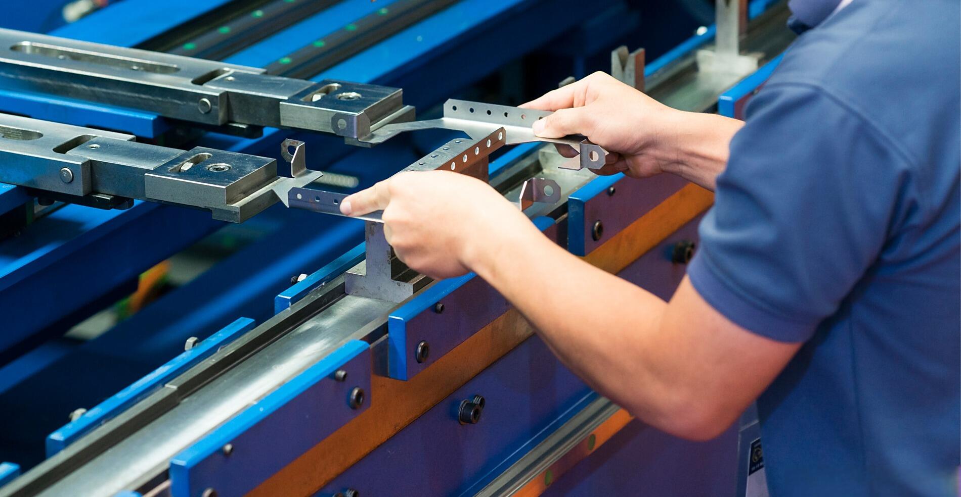
Sheet metal fabrication is a comprehensive process that transforms raw metal sheets into functional components through a series of carefully orchestrated operations. Think of it as the complete journey from a simple flat sheet to a complex three-dimensional part. This manufacturing process encompasses multiple stages, including cutting, bending, forming, and shaping metal into desired configurations.
According to Geomiq's comprehensive guide, sheet metal fabrication creates everything from cellphones and kitchenware to submarines and rockets. The process begins with flat metal sheets of various sizes, thicknesses, and types, which then undergo various processing stages to achieve specific shapes, patterns, and geometries. Fabricators cut, form, and assemble pieces to create containers, chassis, enclosures, frames, brackets, vents, and panels.
While metal fabrication encompasses the entire creation process of transforming raw materials into finished products, welding focuses specifically on joining metal parts through heat and pressure. In essence, welding is one critical component within the broader fabrication workflow - fabrication often includes welding, but not all fabrication projects require it.
The Manufacturing Partnership That Builds Modern Industry
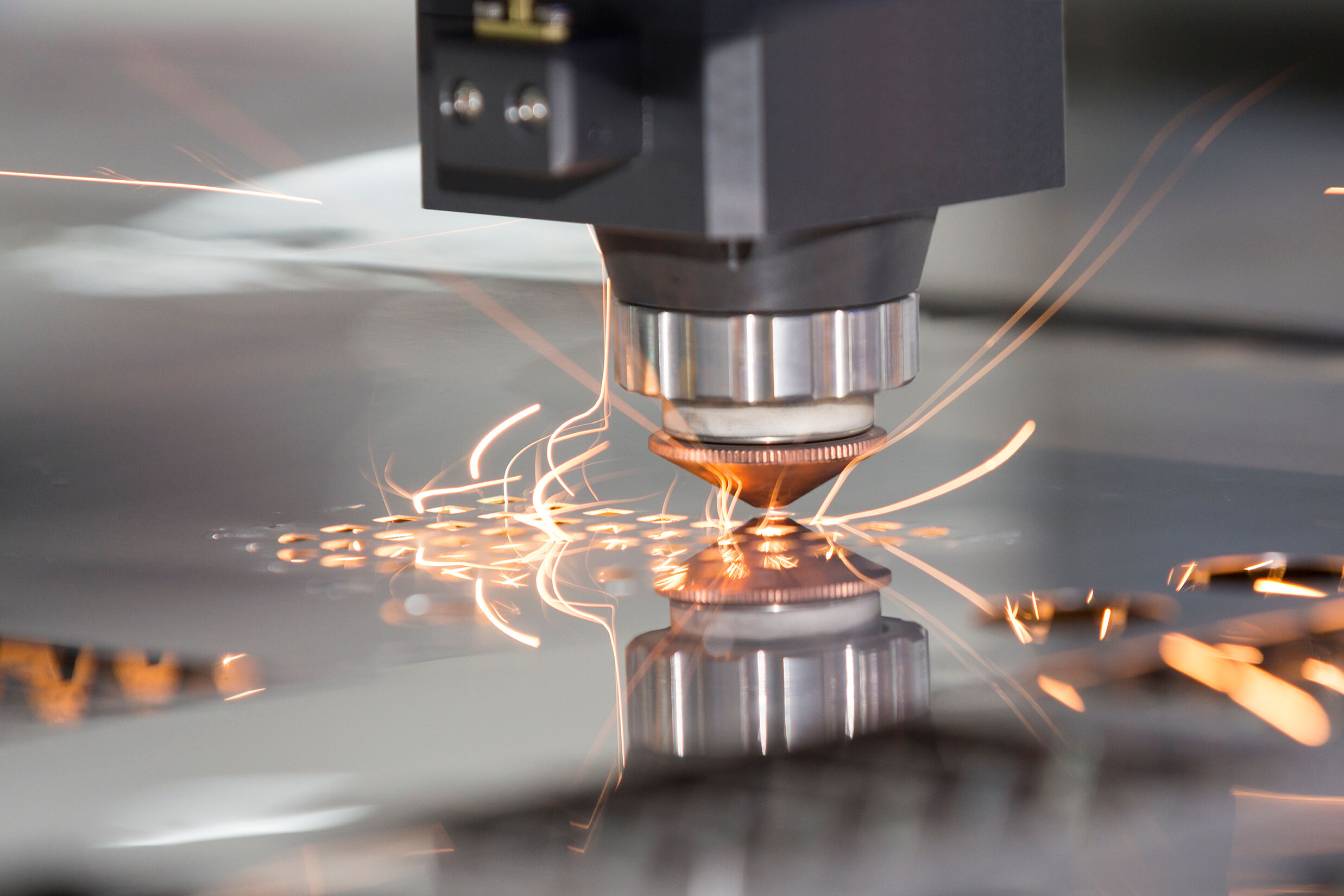
Metal fabrication and welding form a manufacturing partnership that builds virtually every industry you can imagine. Fabrication work typically starts with design and blueprint development, where each component is carefully mapped out using computer-aided design (CAD) software. Once designs are finalized, metal sheets undergo transformation through cutting operations like laser, waterjet, or plasma cutting, followed by forming techniques such as bending, stamping, or deep drawing.
This is where welding enters the picture. As the critical joining technique, welding assembles fabricated components into complete products by fusing metal pieces together. The process typically involves heating metals to their melting points and applying filler material that solidifies into a strong, permanent bond upon cooling. Metal fabrication work relies heavily on this joining capability to create structures that can withstand significant stress and environmental demands.
Where Precision Cutting Meets Permanent Joining
Understanding how metal and fabrication processes integrate with welding is essential for anyone working with sheet metal. The fabrication stage prepares components through precise cutting and forming, while welding provides the permanent bonds that hold everything together. This integration requires careful coordination - parts must arrive consistently positioned and properly prepared for welding to succeed.
When skilled professionals handle both fabrication and welding, the result is a product that withstands heavy use and environmental factors. Whether you're creating building structures, heavy machinery, or automotive components, success depends on understanding this complete workflow. Metal custom work demands expertise across both disciplines to deliver quality results.
Throughout this article, you'll discover how to navigate the entire process - from selecting the right materials and welding methods to preventing the heat distortion that plagues thin materials. You'll learn practical techniques for joint preparation, quality inspection, and cost optimization that professionals use daily. By the end, you'll have a comprehensive framework for approaching any sheet metal project with confidence.
Material Selection and Thickness Considerations for Welding Success
Choosing the right material isn't just about strength or cost - it fundamentally determines which welding methods will work, what parameters you'll need, and whether your finished product will meet quality standards. Before you strike an arc or fire up a laser, understanding how different metals behave under welding heat is crucial for achieving consistent, defect-free results.
Matching Metals to Welding Methods
Each sheet metal type responds differently to welding heat based on its thermal conductivity, melting point, and chemical composition. Making the right match between material and welding method prevents common problems like porosity, cracking, and incomplete fusion.
Carbon steel is the most forgiving material for welding. According to 3ERP's welding guide, mild steel can be welded by most processes, making it ideal for beginners and high-volume production. MIG welding works exceptionally well here, offering fast speeds and good reliability even on thicker materials.
Stainless steel presents unique challenges due to its poor heat conduction. This characteristic causes heat to concentrate in the weld zone, increasing distortion risk. TIG welding typically produces the cleanest results on stainless, though techniques like pulse TIG, staggered stitch welds, and heat sinks help control expansion and contraction.
Aluminum demands precision due to its high thermal conductivity and reflectivity. As noted in GWEIKE's technical documentation, correct focus and gas flow are essential when welding aluminum. TIG welding with AC current is the preferred method because it handles aluminum's oxide layer effectively. MIG welding aluminum is possible but requires specific wire and shielding gas combinations.
Galvanized steel requires extra care because the zinc coating vaporizes during welding, creating fumes and potential porosity. Proper ventilation is mandatory, and welders often need to adjust parameters or remove the coating near weld zones for custom sheet metal work applications.
How Gauge Thickness Changes Everything
Material gauge - the thickness of your sheet metal - dramatically affects every aspect of the welding process. Thin gauges demand precision and careful heat control, while thicker materials require more power and often different techniques entirely.
For thin sheet metal (under 1.5 mm), precision processes like TIG and laser welding excel. These methods minimize heat input, reducing the risk of burn-through and distortion. According to 3ERP's research, TIG welding thin sheet metal produces clean, aesthetically pleasing joints when handled by skilled welders.
When working with medium gauges (1.5 mm to 3 mm), you gain more flexibility in method selection. MIG welding becomes increasingly practical, offering speed advantages without excessive distortion risk. Laser welding parameters in this range typically use 70-85% peak power with wobble widths around 4.5 mm for full penetration on carbon steel.
Thicker sheet metal (over 3 mm) opens up additional options including plasma arc welding and flux core arc welding. These processes deliver the heat input needed for proper fusion without multiple passes, though custom steel fabricators must still manage heat accumulation to prevent warping.
Alloy Considerations for Weld Integrity
Different alloys within the same metal family can respond very differently to welding heat. Understanding these variations helps you select appropriate filler materials and adjust parameters for optimal results.
Aluminum alloys vary significantly in weldability. Series 1xxx, 3xxx, and 5xxx alloys weld relatively easily, while 2xxx and 7xxx series (often used in aerospace) present challenges due to their crack sensitivity. Custom steel fabrications involving mixed alloys require careful filler material selection to prevent galvanic corrosion.
Stainless steel grades also differ substantially. Austenitic grades (304, 316) are generally weldable with proper technique, while martensitic grades may require preheating and post-weld heat treatment. Duplex stainless steels demand precise heat input control to maintain their corrosion-resistant properties.
Welding dissimilar metals presents the greatest challenge. Joining aluminum to steel, for example, is extremely difficult because of their vastly different melting points and thermal expansion rates. Most welding processes fail to create reliable bonds between such combinations, often requiring specialized techniques or mechanical fastening alternatives.
| Material Type | Typical Gauge Range | Recommended Welding Methods | Key Considerations |
|---|---|---|---|
| Carbon Steel | 18-10 gauge (1.0-3.4 mm) | MIG, TIG, Laser, Spot Welding | Most forgiving; excellent for beginners and high-volume production |
| Stainless Steel | 22-14 gauge (0.8-1.9 mm) | TIG, Pulse TIG, Laser | Poor heat conduction increases distortion risk; use heat sinks and clamping |
| Aluminum | 20-12 gauge (0.8-2.7 mm) | TIG (AC), MIG, Laser | High thermal conductivity; requires precise focus, adequate gas flow (≥20 L/min) |
| Galvanized Steel | 20-14 gauge (0.9-1.9 mm) | MIG, Spot Welding | Zinc coating creates fumes; ensure proper ventilation and consider coating removal near welds |
With your material and gauge properly matched to a welding method, the next critical step is understanding the specific techniques available. Each welding process offers distinct advantages for different applications - from MIG's production efficiency to laser's precision capabilities.
Welding Methods Explained From MIG to Laser Technology
Now that you understand how material selection affects your welding outcomes, the next question becomes: which welding method should you actually use? Each technique offers distinct advantages depending on your production requirements, material type, and quality expectations. Let's explore the major methods used in metal fabrication welding, examining not just how they work, but when and why you'd choose each one on the shop floor.
MIG Welding for Production Efficiency
Metal Inert Gas (MIG) welding, technically known as Gas Metal Arc Welding (GMAW), is often the first choice for production environments where speed and cost-effectiveness matter most. The process uses a continuously fed wire that serves as both the electrode and the filler material, making it remarkably efficient for high-volume work.
During MIG welding, an electric arc forms between the wire tip and the workpiece surface. This arc generates enough heat to melt both the wire and the sheet metal, allowing them to fuse together as they cool. A shielding gas - typically argon, CO2, or a mixture - protects the weld pool from atmospheric contamination.
According to 3ERP's welding methods guide, MIG welding is ideal for mild steel and thicker-gauge materials where efficiency takes priority over precision aesthetics. The semi-automatic or fully automatic operation makes it accessible even for less experienced welders, reducing training time and labor costs.
- Advantages: Fast welding speeds, low cost per weld, minimal post-weld cleanup, easy to learn, suitable for automation
- Limitations: Less precise than TIG, not ideal for very thin materials (under 1 mm), requires shielding gas setup, can produce spatter on certain materials
For custom steel work requiring rapid turnaround, MIG welding often delivers the best balance of quality and productivity. Most fabrication shops rely on it for structural components, enclosures, and brackets where weld appearance is secondary to strength and speed.
TIG Welding for Precision and Aesthetics
Tungsten Inert Gas (TIG) welding, or Gas Tungsten Arc Welding (GTAW), represents the precision end of the welding spectrum. Unlike MIG, TIG uses a non-consumable tungsten electrode separate from the filler rod, giving welders exceptional control over heat input and bead placement.
The TIG process requires both hands: one directs the torch and electrode while the other feeds filler material into the weld pool. This manual coordination makes TIG more challenging to master, but the payoff is superior weld quality - especially on thin materials and visible seams.
TIG excels with materials that demand precision handling. Aluminum, titanium, stainless steel, and exotic alloys all respond well to TIG's controlled heat input. For sheet metal under 1.5 mm thick, TIG minimizes the distortion risk that plagues other processes.
- Advantages: Precise heat control, clean and aesthetic welds, works on thin materials, no spatter, excellent for aluminum and stainless steel
- Limitations: Slower than MIG, requires higher skill level, more expensive per weld, not ideal for high-volume production
When your project involves visible seams on consumer products, medical devices, or aerospace components, TIG welding delivers the finish quality that meets exacting standards. Metal fabricators welding thin stainless steel enclosures or aluminum housings typically default to TIG for its unmatched control.
Laser and Resistance Methods for High-Volume Applications
When production volumes climb into the thousands, laser welding and resistance spot welding become increasingly attractive options. Both methods offer speed and consistency that manual processes simply cannot match.
Laser Welding
Laser welding uses a focused beam of light to melt and fuse metal with remarkable precision. The concentrated energy creates a narrow, deep weld with minimal heat-affected zone, making it ideal for thin materials where distortion control is critical.
Modern laser systems can weld at speeds several times faster than traditional arc methods. The non-contact nature of the process means no electrode wear or replacement, and automated systems can run continuously with minimal operator intervention.
- Advantages: Extremely precise, minimal distortion, high automation potential, fast welding speeds, narrow heat-affected zone
- Limitations: High equipment cost, requires precise joint fit-up, limited to thinner materials (typically under 6 mm), specialized training needed
Resistance Spot Welding
Spot welding creates localized joints by concentrating electrical current through overlapping metal sheets. According to resistance welding specialists, the process is so fast that a single weld completes in a fraction of a second - which explains why a modern car body contains between 2,000 and 5,000 individual spot welds.
The process works by clamping two sheets between copper alloy electrodes, then passing high current through the joint. The metal's natural resistance generates intense heat at the contact point, forming a molten nugget that solidifies into a strong bond. No filler material, flux, or shielding gas is required.
- Advantages: Extremely fast, easily automated, no consumables required, low deformation, cost-effective for mass production
- Limitations: Limited to overlapping lap joints, only suitable for thin sheets (up to 3 mm), high initial equipment cost, requires electrode access to both sides
Spot welding dominates automotive manufacturing for good reason - it's perfectly suited for joining thin steel panels quickly and consistently. For metal fabricators and welding operations producing high volumes of sheet metal assemblies, the initial investment in spot welding equipment pays dividends through reduced cycle times and labor costs.
Plasma Arc Welding
Plasma arc welding (PAW) bridges the gap between TIG welding and laser welding. Like TIG, it uses a tungsten electrode, but the arc is constricted through a small orifice that creates a high-velocity plasma jet. This concentration delivers excellent precision with faster travel speeds than conventional TIG.
The adjustable current makes plasma arc welding versatile across different gauges. For very thin sheet metal, the process offers fine control with low distortion risk - making it valuable for aerospace, electronics, and medical device manufacturing where precision is non-negotiable.
- Advantages: High precision, faster than TIG, excellent for thin materials, low power demands, clean aesthetics
- Limitations: More expensive than MIG or TIG, requires specialized equipment and training, narrower application range than other processes
The table below provides a quick comparison of these metal fabrication & welding methods to help guide your selection:
| Welding Method | Best Applications | Speed | Precision | Cost per Weld |
|---|---|---|---|---|
| MIG (GMAW) | Mild steel, structural components, enclosures | High | Medium | Low |
| TIG (GTAW) | Aluminum, stainless steel, visible seams, thin materials | Low | High | Medium-High |
| Laser | Precision components, automation, thin sheets | Very High | Very High | High (equipment), Low (per unit at volume) |
| Spot Welding | Automotive panels, appliances, mass production | Very High | Medium | Very Low at volume |
| Plasma Arc | Aerospace, electronics, medical devices | Medium-High | High | Medium-High |
Selecting the right welding method is only half the equation. Even the best technique will fail if joints aren't properly designed and prepared. Understanding joint types, edge preparation, and fit-up tolerances is what separates professional-quality welds from problematic ones.
Joint Design and Preparation Requirements
You've selected your material and chosen your welding method - but here's where many projects go wrong. Poor joint design and inadequate preparation cause more weld failures than any other factor. Whether you're working on custom cut sheet metal components or large structural assemblies, the quality of your finished weld depends heavily on what happens before you ever strike an arc.
Joint Types and When to Use Each
Understanding the five fundamental joint types helps you choose the right configuration for your specific application. Each joint type offers distinct advantages depending on load requirements, material access, and aesthetic considerations.
Butt joints connect two pieces of metal aligned edge-to-edge in the same plane. They're ideal when you need a flush surface and maximum strength along the weld line. For thin sheet metal, square butt joints (no edge beveling) work well when full penetration isn't critical. Thicker materials may require beveled edges to ensure complete fusion through the joint.
Lap joints overlap two metal pieces, creating a broader contact area. This configuration is forgiving of minor fit-up variations and works exceptionally well for spot welding applications. Lap joints are common in custom metal cutting operations where panels need to be joined without precise edge matching.
Corner joints form 90-degree angles between two pieces. According to Approved Sheet Metal's technical guide, both open and closed corner configurations exist. Open corners leave a gap at the intersection, while closed corners (also called square butt joints at corners) position edges flush against each other. The primary challenge with both types is preventing heat deformation and warping - a critical consideration for thin materials.
T-joints connect one piece perpendicular to another, forming a T-shape when viewed from the end. These joints appear frequently in structural frames and brackets. Fillet welds on one or both sides provide the necessary strength, though access constraints sometimes limit welding to a single side.
Edge joints join two parallel pieces along their edges, typically used for flanged connections or when reinforcing sheet metal assemblies. While not as strong as other joint types under tensile loading, edge joints work well for non-structural applications and metal cutting and bending services that produce flanged components.
Edge Preparation That Prevents Defects
Proper edge preparation eliminates many common weld defects before they can occur. Skipping or rushing this step leads to lack of fusion, porosity, and cracking - problems that require costly rework or part rejection.
According to Hobart Brothers' technical research, take care with fit-up and joint design to prevent weld failures. When presented with poor fit-up conditions, welders often compensate by creating wider weld beads to fuse the metal together. The danger in doing so is that the resulting weld may have too thin of a throat, causing it to be weak and create stress on the center of the weld - a condition called bead-shape cracking.
Cleaning is equally critical. Remove all oil, grease, rust, mill scale, and oxide layers from the weld zone. For aluminum, this means breaking through the tenacious oxide layer immediately before welding. For galvanized steel, consider removing the zinc coating near the joint to prevent porosity from zinc vaporization. Custom metal fab operations that skip cleaning steps consistently produce inferior welds.
Layout Techniques for Accurate Fit-Up
Accurate layout ensures components align properly before welding begins. Three primary techniques help fabricators achieve precise positioning:
Parallel line development works best for cylindrical and conical shapes where elements run parallel to a central axis. This technique is common when preparing custom metal cuts for ducting and pipe applications.
Radial line development suits components where all lines radiate from a single point, such as cones and transition pieces. Proper radial layout prevents gaps and overlaps that compromise weld quality.
Triangulation handles complex shapes that don't fit parallel or radial methods. By dividing surfaces into triangles, fabricators can develop accurate flat patterns that assemble with proper fit-up.
Step-by-Step Joint Preparation Process
- Verify dimensions: Check all cut pieces against design specifications. For sheet metal joints, maintain fit-up tolerances of ±0.5 mm for thin materials and ±1.0 mm for thicker gauges.
- Prepare edges: Bevel or chamfer edges as required by the welding procedure. A good depth-to-width ratio for the resulting weld bead is 5:1 to 2:1.
- Clean thoroughly: Remove contaminants from at least 25 mm on each side of the weld zone using appropriate solvents, grinding, or wire brushing.
- Position and align: Use layout marks, fixtures, or jigs to position components accurately. Verify alignment at multiple points along the joint.
- Establish root gap: Maintain consistent spacing between pieces - typically 0 to 2 mm for thin sheet metal depending on the welding method and joint type.
- Apply tack welds: Secure the assembly with properly spaced tack welds that hold alignment without introducing excessive heat. Space tacks every 50-100 mm for thin materials.
- Final inspection: Verify fit-up tolerances and alignment before proceeding to full welding. Correcting problems now prevents defects later.
Even with perfect joint preparation, thin sheet metal presents a unique challenge that derails many projects: heat distortion. The very properties that make thin materials easy to form also make them susceptible to warping during welding - a problem that requires specific prevention strategies to overcome.
Preventing Heat Distortion and Warping in Thin Materials
Spend five minutes in any fabrication shop, and someone will show you a panel that looked perfect until the weld cooled - then twisted into a warped mess. Thin sheet metal, typically anything under 3/32 inch (2.4 mm), simply lacks the mass to resist welding heat. One solid bead and the entire piece cups, bows, or waves like a flag. Understanding why this happens - and how to prevent it - separates frustrating scrap piles from successful projects.
Why Thin Metal Warps During Welding
The physics behind welding distortion is straightforward: heat the metal, and it expands. Cool it quickly, and it contracts. The weld zone and surrounding heat-affected zone (HAZ) cool faster than the rest of the sheet, creating shrinkage forces that pull against the cooler metal. According to welding distortion research, thick plates can absorb and distribute this stress. Thin sheets simply fold like paper.
The heat-affected zone presents particular challenges for custom sheet metal bending applications. As noted by thin metal welding specialists, a large HAZ created during welding can weaken the material, causing brittleness, reduced strength, or discoloration. Thin metals have reduced tolerance to heat - there's simply not enough mass to soak it up and spread it around. The hot zone concentrates right where the arc hits, shrinkage intensifies, and the sheet has no stiffness to push back.
Residual stress compounds the problem. Even after cooling, internal stresses remain locked in the panel. These stresses can cause delayed distortion, cracking at stress concentrations, or unexpected failures under load. For custom metal bending operations that require precise final dimensions, understanding and controlling these thermal effects is essential.
Fixturing and Clamping Strategies
Proper fixturing is your first line of defense against distortion. Strong fixtures, copper backing bars, and aluminum chill blocks hold the sheet dead flat while pulling heat away from the weld zone. The goal is constraining movement while providing thermal mass to absorb excess energy.
Heat sinks work by conducting heat away from critical areas before it can cause expansion. Copper and aluminum make excellent heat sink materials due to their high thermal conductivity. Position them directly behind or adjacent to the weld area. One experienced fabricator keeps wet rags handy and applies them to the backside immediately after laying a bead - a simple but effective technique for stainless steel work.
Backing bars serve double duty: they support the weld pool to prevent burn-through and absorb excess heat that would otherwise distort the panel. For metal bending service applications where final dimensions are critical, investing in proper fixturing pays dividends in reduced rework and scrap.
- Copper backing bars: Excellent thermal conductivity pulls heat away quickly; prevents burn-through on thin materials
- Aluminum chill blocks: Lightweight alternative that still provides effective heat absorption
- Steel fixtures: Hold parts in position but provide less heat sinking; use when dimensional control matters more than thermal management
- Wet rags or cooling paste: Quick shop-floor solution for localized cooling; effective on stainless steel and aluminum
Welding Sequences That Minimize Distortion
How you sequence your welds matters as much as your equipment settings. The fundamental principle: never run one long bead from start to finish. Instead, distribute heat across the workpiece to prevent localized buildup that causes warping.
Tack welding establishes your foundation. Place small tack welds - roughly 1/4-inch stitches - every couple of inches along the joint before beginning full welding. These tacks lock the joint geometry in place and provide reference points that resist distortion as you complete the weld.
Skip welding (intermittent welding) prevents heat concentration by jumping around the workpiece. Weld an inch here, skip four inches, weld another inch elsewhere. This technique lets one spot cool while you work somewhere else, spreading thermal stress across the entire panel rather than concentrating it in one area. For custom bent sheet metal assemblies with long seams, skip welding often makes the difference between success and scrap.
Backstep welding involves welding toward your starting point rather than away from it. Start each segment where the previous one ended, but weld back toward the beginning. This counterintuitive approach balances shrinkage forces and keeps the overall panel flatter than continuous forward welding.
Balanced welding applies to assemblies with welds on multiple sides. Alternate between opposite sides to balance shrinkage forces - weld one side, flip, weld the opposite side, repeat. This prevents the cumulative pull that bows panels in one direction.
- Keep amps low and move fast: Less total heat input means less distortion potential
- Use pulse welding when available: Delivers heat in controlled bursts with cooling periods between pulses
- Make multiple light passes instead of one heavy pass: Allows cooling between passes and reduces peak temperatures
- Weld vertical-down on thin materials: Creates adequate penetration with less amperage, filler, and time
Post-Weld Straightening Methods
Despite best efforts, some distortion may still occur. Fortunately, several correction techniques can restore flatness without compromising weld integrity.
Mechanical straightening using hammer and dolly remains the most common approach. As described by Miller Welds' fabrication guide, apply a guide coat (spray paint or dykem), sand the surface with a block, and the coating remains on low spots - showing exactly where stretching is needed. Hammer work stretches the shrunk areas back to their proper dimensions.
Planishing hammers work efficiently on larger areas where hand hammer and dolly become impractical. The rapid, controlled strikes stretch metal uniformly without the fatigue of manual hammering.
Heat straightening - applying controlled heat to the opposite side of the distortion - can pull warped panels back into alignment. However, this technique requires experience to avoid creating new problems. TIG welding produces softer welds that respond better to post-weld stretching and are less likely to crack during correction.
For production environments, understanding which post-weld corrections your process typically requires helps optimize both the welding parameters and the straightening workflow. Preventing distortion is always preferable to correcting it, but knowing your correction options ensures that minor warping doesn't become expensive scrap.
With distortion prevention techniques in your toolkit, the next consideration is ensuring your welds meet quality standards. Understanding inspection methods and certification requirements helps you verify that your work performs as designed.
Quality Standards and Inspection Methods
You've prevented distortion, nailed your joint preparation, and laid down what looks like a solid weld. But how do you actually prove it meets specifications? Whether you're running a custom fabrication shop or managing quality for industrial metal fabrication services, understanding weld quality standards separates professional work from guesswork. The standards you follow and inspection methods you employ determine whether your welds pass customer audits, regulatory requirements, and real-world performance tests.
AWS and ISO Standards That Matter
Two major standards systems govern welding quality worldwide: the American Welding Society (AWS) standards and International Organization for Standardization (ISO) standards. Which one applies to your project depends largely on geography and industry requirements.
According to Seather Technology's standards comparison, AWS standards dominate in the United States, while ISO standards apply to global projects and international clients. Many sheet metal fabrication shops working with multinational customers need familiarity with both systems.
AWS D1.1 is the cornerstone document for structural steel welding. It covers design, inspection, and qualification requirements for buildings, bridges, and heavy fabrication. The standard specifies acceptable weld profiles, permissible defects, and testing requirements that inspectors use to evaluate quality sheet metal and welding work.
ISO 9606-1 focuses on welder qualification rather than structural design. This standard explains certification procedures, testing methods, and validity periods for welders working on general fabrication projects. When customers specify ISO compliance, they're typically concerned with ensuring your welders have demonstrated their skills through standardized testing.
One critical difference affects how you read drawings: AWS uses a single reference line for most weld symbols, while ISO adds a dashed line indicating welds on the opposite side. This seemingly small distinction can cause significant errors if you're accustomed to one system and encounter the other. Similarly, AWS measures fillet weld sizes by leg length, while ISO measures throat thickness - using the wrong measurement could result in undersized or oversized welds.
When you learn the differences between AWS and ISO, you can read drawings the right way. This helps you avoid mistakes and keeps your projects running smoothly.
Visual and Dimensional Inspection Criteria
Visual testing (VT) remains the first and most fundamental inspection method for quality custom metal fabrication. A trained inspector examines welds for surface defects including cracks, porosity, undercut, incomplete fusion, and improper bead profile. No special equipment is required beyond good lighting and possibly magnification for detailed examination.
Visual inspection criteria typically address:
- Weld profile: Proper convexity or concavity within specified limits; no excessive reinforcement
- Surface porosity: Maximum acceptable pore size and distribution
- Undercut: Depth limits based on material thickness and application
- Cracks: Generally zero tolerance for any visible cracking
- Spatter: Removal requirements based on application and finish specifications
Dimensional verification ensures welds meet size specifications and assemblies conform to design tolerances. Inspectors use weld gauges to measure leg length, throat thickness, and reinforcement height. For sheet metal fabrication shops producing precision assemblies, dimensional accuracy often matters as much as structural integrity.
Proper documentation supports both inspection methods. Maintain records of inspection results, welder qualifications, and any corrective actions taken. This documentation proves invaluable during customer audits and helps identify recurring issues that require process improvements.
Certification Requirements for Quality Assurance
Professional certification establishes credibility for both individual welders and fabrication facilities. Certification requirements vary by standard, industry, and customer specifications.
For AWS D1.1 compliance, welders must pass qualification tests demonstrating their ability to produce acceptable welds using specific processes, positions, and materials. According to the reference documentation, AWS requires proof of welding activity every six months to maintain certification. If a welder stops practicing their certified process for more than six months, requalification testing becomes necessary.
ISO 9606-1 certification typically remains valid for three years, provided the welder continues practicing the certified welding process. The certification process involves testing by a Notified Body - an approved organization authorized to verify compliance with the standard. Some ISO certifications apply only to specific projects, so always verify your documentation covers the work at hand.
Fabrication shop certifications go beyond individual welder qualifications. Quality management system certifications like ISO 9001 demonstrate that a facility maintains documented procedures, calibrated equipment, and continuous improvement processes. Industry-specific certifications such as IATF 16949 for automotive or AS9100 for aerospace signal compliance with sector-specific requirements that customers in those industries expect.
| Inspection Method | Application | Defects Detected | Limitations |
|---|---|---|---|
| Visual Testing (VT) | All welds; first-line inspection | Surface cracks, porosity, undercut, profile issues, spatter | Surface defects only; requires trained inspector |
| Radiographic Testing (RT) | Critical structural welds; code requirements | Internal porosity, inclusions, incomplete fusion, cracks | Expensive; radiation safety concerns; limited on thin materials |
| Ultrasonic Testing (UT) | Thick sections; production environments | Internal discontinuities, lack of fusion, cracks | Requires skilled operator; less effective on thin sheet metal |
| Bend Testing | Welder qualification; procedure validation | Ductility issues, fusion problems, internal defects | Destructive; samples only; cannot test production parts |
| Dimensional Verification | All welds requiring size conformance | Undersized welds, excessive reinforcement, misalignment | Surface measurements only; requires proper gauges |
Non-destructive testing (NDT) methods like radiographic testing (RT) and ultrasonic testing (UT) detect internal defects invisible to visual inspection. However, these methods have practical limitations for typical sheet metal applications. RT requires radiation safety protocols and becomes less effective on very thin materials. UT works best on thicker sections where sound wave propagation provides meaningful data. For most custom fabrication services involving thin sheet metal, visual inspection combined with dimensional verification and periodic destructive testing of sample welds provides adequate quality assurance.
With quality standards and inspection methods established, the next step is understanding how these requirements vary across different industries. Automotive, aerospace, HVAC, and electronics applications each bring unique specifications that influence material selection, welding methods, and certification expectations.
Industry Applications From Automotive to Aerospace
Ever notice how a car body panel feels different from an aircraft skin or an HVAC duct? That's not just material choice - it's the result of vastly different welding requirements driven by each industry's unique demands. What passes inspection in one sector might fail catastrophically in another. Understanding these industry-specific differences helps custom metal fabricators deliver work that meets the exacting standards customers expect.
Automotive Structural Component Requirements
The automotive industry consumes more sheet metal welding than virtually any other sector. According to industry research, a modern car body contains between 2,000 and 5,000 individual spot welds - each one critical to crash safety, structural integrity, and long-term durability.
Automotive welding demands exceptional repeatability at high volumes. Body panels, chassis parts, brackets, and load-bearing structures must meet tight tolerances while flowing through production lines at speeds measured in units per minute, not per hour. This environment favors resistance spot welding for its speed and consistency, though arc and laser welding provide deeper penetration for structural and load-bearing components.
Material selection in automotive applications increasingly involves Advanced High-Strength Steels (AHSS) that offer higher strength with reduced thickness - supporting both crash safety and weight reduction goals. Aluminum alloys appear wherever lightweighting and fuel efficiency take priority. This multi-material approach directly influences forming, joining, and finishing processes across production lines.
- Primary materials: AHSS, mild steel, aluminum alloys, galvanized steel
- Dominant welding methods: Resistance spot welding, laser welding, MIG for structural components
- Key certifications: IATF 16949 (automotive quality management), OEM-specific approvals
- Tolerance expectations: ±0.5 mm typical for body panels; tighter for safety-critical assemblies
- Critical considerations: High-volume repeatability, crash performance validation, mixed-material joining
For automotive projects requiring certified quality, manufacturers like Shaoyi (Ningbo) Metal Technology demonstrate how IATF 16949 certification translates into reliable production. Their combination of 5-day rapid prototyping and automated mass production for chassis, suspension, and structural components illustrates the capability level that automotive OEMs expect from their supply chain partners.
Aerospace and Medical Device Precision Standards
If automotive welding demands consistency, aerospace welding demands perfection. According to aerospace engineering standards, the margins for error are razor-thin, and a single flaw in a weld can compromise entire missions or put lives at risk.
AWS D17.1 stands as the cornerstone standard governing fusion welding for aerospace components. First published in 1999 by the American Welding Society, this standard applies globally across aircraft, spacecraft, and UAV manufacturing. Its criteria guide everything from welder qualification and WPS development to inspection classes and material-specific rules for nickel alloys, titanium, and high-performance composites.
Aerospace materials present unique welding challenges. Titanium is highly reactive at high temperatures, requiring inert gas shielding to prevent contamination. Nickel alloys can suffer from hot cracking and segregation during fusion welding. AWS D17.1 outlines specific pre-weld preparation, filler material compatibility, and post-weld inspection procedures for these critical metals.
The standard classifies welds into inspection classes based on criticality:
- Class A: Highest criticality - primary structure where failure is catastrophic; requires most rigorous NDT
- Class B: Moderate criticality - secondary structures; standard inspection protocols
- Class C: Lowest criticality - non-structural applications; visual inspection may suffice
Medical device manufacturing shares aerospace's precision demands, particularly for implantable devices and surgical instruments. These applications typically require TIG welding for its clean aesthetics and precise heat control. Contractor metal works serving medical clients must maintain meticulous documentation and often require FDA-compliant quality systems alongside traditional welding certifications.
- Primary materials: Titanium, nickel alloys (Inconel), stainless steel, aluminum
- Dominant welding methods: TIG, electron beam, laser welding
- Key certifications: AWS D17.1, NADCAP, AS9100
- Tolerance expectations: Often ±0.1 mm or tighter for critical joints
- Critical considerations: Material traceability, welder qualification documentation, non-destructive testing requirements
HVAC and Enclosure Application Considerations
HVAC ductwork and electronics enclosures occupy different territory - they demand quality fabrication without aerospace price tags. Yet these applications still require careful attention to material selection, joint design, and finishing to ensure long-term performance.
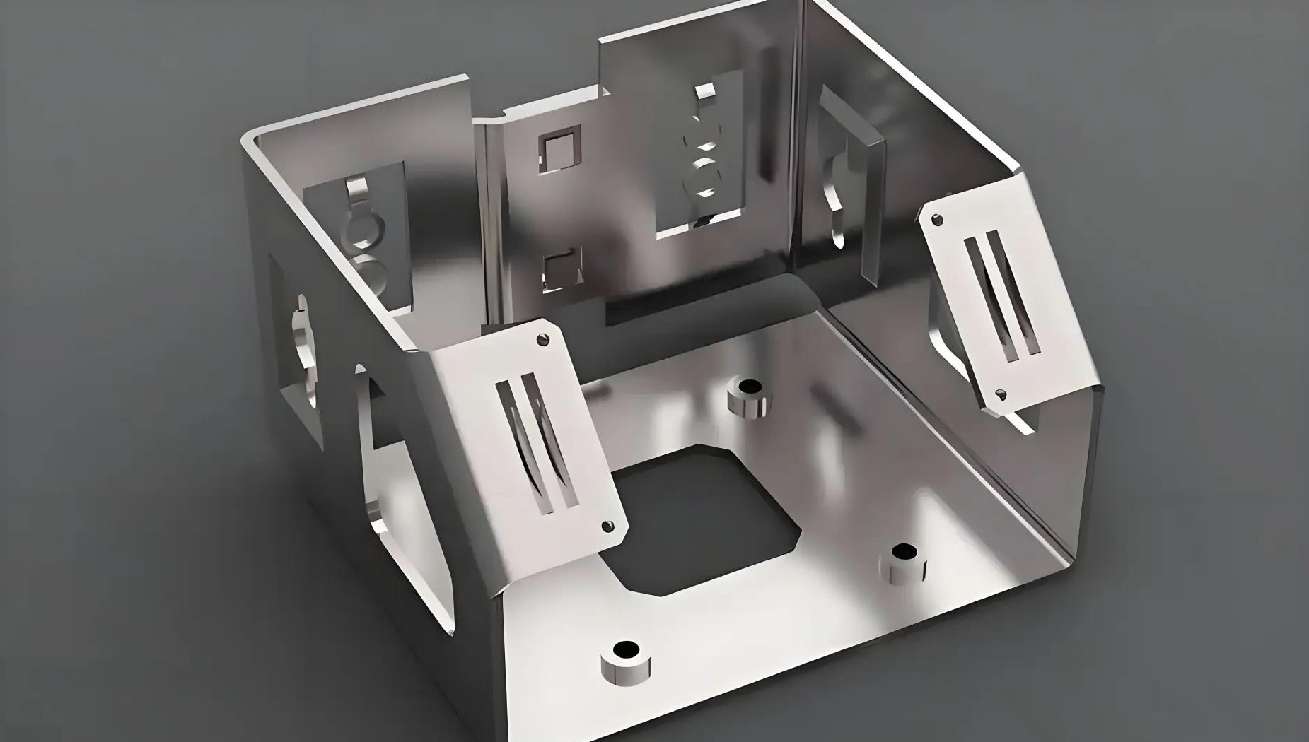
According to enclosure fabrication specialists, sheet metal enclosures protect components and provide mounting, grounding, and environmental shielding. Typical formats include U-shape chassis, L-brackets, clamshell boxes, rackmount units, and multi-part assemblies with doors and panels.
Material selection for enclosures balances performance requirements against cost:
- Cold-rolled steel: Strong and cost-effective for painted indoor applications; requires coating for corrosion resistance
- Galvanized steel: Built-in corrosion resistance and paint adhesion; watch for zinc fumes during welding
- Aluminum: Light, corrosion-resistant, good thermal conductivity; anodize or powder coat for durability
- Stainless steel: Excellent corrosion resistance for food, medical, or outdoor applications; higher cost and forming difficulty
Welding methods for enclosures typically include spot welding for quick, low-distortion lap joints and TIG or MIG for structural seams. Many custom metal fabrications in this sector use riveting or clinching for mixed-material or finish-critical assemblies where welding would compromise appearance.
EMI/RFI shielding requirements add another dimension to enclosure welding. Maintaining metal-to-metal continuity across seams often requires conductive gaskets, chem-film treatments on aluminum, or zinc plating on steel. Paint must be kept back from ground points to ensure electrical continuity.
HVAC applications focus on different priorities - primarily air-tight seams and corrosion resistance in varying environmental conditions. Galvanized steel dominates this sector, with spot welding and seam welding providing the continuous joints needed for duct integrity. Contractor metal works serving HVAC clients must understand airflow requirements, accessibility for service, and code compliance for fire ratings.
- Enclosure standards: NEMA ratings (U.S.) or IP codes (international) for environmental protection
- HVAC codes: SMACNA standards, local building codes, fire ratings
- Typical tolerances: ±0.5 mm for critical mating surfaces; looser for general assemblies
- Finishing requirements: Powder coating, anodizing, or plating based on environment and appearance needs
These industry-specific requirements translate directly into cost implications. Aerospace and medical projects command premium pricing to cover extensive documentation, specialized materials, and rigorous inspection. Automotive volumes offset per-unit costs but demand substantial upfront investment in automation and quality systems. HVAC and enclosure work typically offers the most accessible entry point for custom metal fabricators building their capabilities.
Understanding which industry your project serves - and what that industry expects - helps you quote accurately, prepare appropriately, and deliver work that meets customer expectations. With industry requirements clarified, the next consideration is understanding how these factors affect your project costs and what design decisions can optimize your manufacturing budget.
Cost Factors and Design for Manufacturability
You've selected your materials, chosen your welding method, and understand your industry requirements - but can your budget actually support your plan? Cost estimation in sheet metal fabrication and welding trips up even experienced project managers because the obvious expenses often pale compared to hidden factors. Labor, not materials, typically dominates your welding costs. Design decisions made months before production begins lock in expenses you can't recover. Understanding these dynamics helps you quote accurately and identify optimization opportunities before they disappear.
Cost Drivers in Welding Method Selection
One common misconception is that consumables - gas, filler wire, flux, electrodes - represent the path to cost savings. According to MATHESON's weld cost analysis, many fabricators find it easier to add up consumable costs versus quantifying other weld-related expenses. However, cost reductions derived from labor savings and quality improvements are typically more impactful, more controllable, and more sustainable.
Think about it this way: your welder's hourly rate applies whether they're laying perfect beads or grinding out defects and starting over. Every minute spent on rework, repositioning, or waiting for parts to cool is labor cost that produces nothing. That's why welding method selection should prioritize the total cost equation, not just the per-weld expense.
Each welding process carries different labor intensity profiles. TIG welding, while producing beautiful results, moves slowly and demands skilled operators who command higher wages. MIG welding sacrifices some precision for dramatically faster travel speeds, reducing labor hours per assembly. Laser and resistance welding methods require significant capital investment but slash per-unit labor costs when volumes justify the equipment.
Equipment requirements extend beyond the welding power source itself. Consider fixturing, positioning equipment, ventilation systems, and safety gear. A custom fabrication shop investing in proper fixtures might spend more upfront but recover that investment through reduced rework and faster throughput. Metal repair services often face different equipment calculations than production fabricators since repair work demands flexibility over specialization.
| Cost Factor | MIG Welding | TIG Welding | Laser Welding | Spot Welding |
|---|---|---|---|---|
| Initial Equipment Cost | Low-Medium | Medium | High | Medium-High |
| Labor Intensity | Medium | High | Low | Low |
| Skill Level Required | Medium | High | Medium | Low-Medium |
| Consumable Costs | Medium | Medium-High | Low | Very Low |
| Speed/Throughput | Medium-High | Low | Very High | Very High |
| Post-Weld Cleanup | Medium | Low | Very Low | Very Low |
| Automation Potential | High | Medium | Very High | Very High |
Volume Considerations and Automation Benefits
Production volume fundamentally changes your cost optimization strategy. What makes economic sense for ten assemblies differs dramatically from calculations for ten thousand.
Low-volume and prototype work favors manual welding methods with minimal setup costs. Your small metal fabrication shop can quote competitive prices on short runs because you're not amortizing expensive automation across few units. Flexibility matters more than cycle time when every job looks different. Custom fab and repair operations thrive in this space precisely because manual skills adapt to varied requirements without retooling.
As volumes increase, the automation calculation shifts. According to fabrication cost research, automated welding uses machines, robots, and computer-controlled systems to perform welding operations with precision and consistency that manual operators struggle to match over extended production runs. The upfront investment in robotic cells or automated fixtures spreads across thousands of units, driving per-piece costs well below manual alternatives.
The break-even point varies by application, but consider these factors when evaluating automation:
- Consistency requirements: Robots don't get tired, distracted, or vary their technique as shifts progress
- Labor availability: Skilled welders are increasingly difficult to hire and retain; automation reduces dependency
- Quality costs: Automated systems produce fewer defects, reducing scrap and rework expenses
- Throughput needs: When demand exceeds manual capacity, automation may be the only viable path to growth
Many companies find a hybrid approach works best - using manual welding for custom or complex tasks while relying on automation for high-volume, repetitive production. This balance ensures cost-efficiency without sacrificing the flexibility needed for varied customer requirements.
Design Decisions That Impact Your Budget
Here's what most project managers miss: by the time parts arrive for welding, roughly 80% of your manufacturing costs are already locked in. Design decisions made during engineering determine material selection, joint complexity, tolerance requirements, and process choices that drive production expenses. This reality makes Design for Manufacturability (DFM) principles essential for cost optimization.
According to Protolabs' DFM guidance, getting a grip on the best practices of design for manufacturing for sheet metal fabrication is an excellent way to reduce costs and improve part quality. A misstep early in the process can mean costly rework or potential product failures.
Common design decisions that inflate costs include:
- Over-specified tolerances: Tighter tolerances than functionally necessary increase inspection time and rejection rates
- Complex joint configurations: Multiple weld orientations requiring repositioning add labor and fixturing costs
- Inaccessible weld locations: Joints that welders or robots cannot easily reach require creative (expensive) solutions
- Mixed materials: Dissimilar metal joints demand specialized processes and often compromise quality
- Inadequate bend reliefs: Missing or undersized reliefs cause forming problems that require rework or scrap
Professional fabrication partners offer DFM support precisely because catching these issues early prevents expensive corrections later. For example, manufacturers like Shaoyi (Ningbo) Metal Technology provide comprehensive DFM support alongside their 5-day rapid prototyping capability - enabling customers to validate designs and identify optimization opportunities before committing to production tooling. Their 12-hour quote turnaround helps project teams evaluate alternatives quickly, comparing cost implications of different design approaches while timelines remain flexible.
When evaluating potential custom metal fabrication shop partners, consider how their DFM capabilities align with your project stage:
- Early concept phase: Partners who can prototype quickly help you iterate designs before freezing specifications
- Design finalization: DFM review identifies manufacturing challenges while changes remain inexpensive
- Production transition: Partners with both prototyping and volume capabilities simplify qualification and reduce handoff risks
The decision between in-house fabrication and outsourcing depends on your volume, capability gaps, and strategic priorities. A custom metal shop handling diverse projects in-house builds institutional knowledge but faces equipment utilization challenges. Outsourcing to specialized partners provides access to capabilities without capital investment but requires careful supplier management.
For projects requiring both prototype validation and eventual volume production, working with partners who span that spectrum - from rapid prototyping through automated mass production - eliminates the transition risks that often introduce quality problems and schedule delays. Understanding your project's full lifecycle helps you structure partnerships that optimize total cost rather than individual phase expenses.
With cost factors clarified, the final consideration is synthesizing everything you've learned into a practical decision framework. Matching your specific project requirements to the right fabrication and welding approach requires balancing technical factors, cost constraints, and capability assessments.
Selecting the Right Fabrication and Welding Approach
You've absorbed a lot of information - material selection, welding methods, joint preparation, distortion prevention, quality standards, industry requirements, and cost factors. Now comes the practical question: how do you pull all these pieces together for your specific project? The answer isn't a single "best" approach but rather a systematic evaluation that matches your requirements to available methods and resources.
Matching Your Project to the Right Approach
Every successful fabrication project starts with honest assessment. Before selecting materials or methods, work through these fundamental questions that shape every downstream decision:
- Define your functional requirements: What loads, environments, and service conditions must your finished product withstand? Structural chassis components demand different approaches than decorative enclosures.
- Identify your material constraints: Does your application require specific alloys for corrosion resistance, weight targets, or thermal properties? Material choice immediately narrows your welding method options.
- Assess your volume expectations: Are you producing prototypes, hundreds, or thousands of units? Volume determines whether manual flexibility or automated consistency makes economic sense.
- Evaluate your tolerance requirements: How precise must your finished dimensions be? Tighter tolerances demand more controlled processes and increase both equipment and inspection costs.
- Consider your timeline: Does your schedule allow for tooling development and process optimization, or do you need parts next week? Urgency often favors manual methods even when automation would ultimately cost less.
- Audit your internal capabilities: Do you have the equipment, skills, and quality systems to execute in-house? Be honest about gaps that require either investment or outsourcing.
- Calculate your budget constraints: What can you actually spend on tooling, labor, and quality verification? Budget realities sometimes override technical preferences.
Working through this checklist before committing to an approach prevents the costly mid-project pivots that plague poorly planned fabrication work. A custom fabricator who skips this assessment often discovers problems only after materials are cut and fixtures are built.
Emerging Technologies Shaping the Industry
Sheet metal fabrication and welding aren't standing still. According to industry research, the robotic welding market was valued at $7.8 billion in 2022 and is projected to grow at a CAGR of over 10% through 2032. Understanding where the industry is heading helps you make investments that remain relevant.
Collaborative robots (cobots) are democratizing automation for small and mid-sized manufacturers. Unlike traditional industrial robots that operate in isolated cells, cobots work safely alongside human operators without extensive infrastructure changes. They're easier to program, more flexible, and increasingly equipped with AI-driven sensors that adapt to complex welding scenarios. For custom metal working operations that previously couldn't justify full automation, cobots offer an accessible entry point.
AI-powered welding systems now optimize parameters in real-time. These systems analyze arc stability, penetration depth, and joint alignment, adjusting on the fly to ensure consistent results. Computer vision detects defects during welding rather than after, reducing rework. According to the research, AI can predict equipment failures before they occur and optimize welding parameters based on material type and thickness - capabilities that were science fiction a decade ago.
Fixtureless welding represents another frontier. Advanced seam tracking and 3D vision systems detect part geometry and adjust torch paths dynamically. This technology handles variations in part dimensions, thermal distortion, and imperfect edge preparation without custom fixtures for every job. For metal custom fabrication operations handling high-mix, low-volume work, eliminating fixture costs and setup time dramatically improves economics.
Industry 4.0 integration connects welding systems to broader manufacturing ecosystems. IoT-enabled robots monitor performance metrics, send maintenance alerts, and integrate with MES and ERP platforms for seamless production tracking. This connectivity transforms welding from a standalone process into a smart, data-driven component of modern manufacturing.
Even sustainability is reshaping the landscape. Battery-powered portable welders, laser welding, and friction stir welding reduce energy consumption and emissions while eliminating some consumables entirely. Manufacturers facing environmental regulations or seeking operational cost reductions increasingly favor these eco-conscious approaches.
Making the Build-or-Buy Decision
One of the most consequential decisions you'll face is whether to develop internal fabrication capabilities or partner with external specialists. Neither answer is universally correct - the right choice depends on your specific circumstances.
Consider in-house fabrication when:
- You have consistent, predictable volume that justifies equipment investment
- Proprietary designs require protection from external exposure
- Rapid iteration and engineering integration drive your competitive advantage
- You can attract and retain skilled technical staff in your market
- Quality control requires direct oversight that outsourcing complicates
Consider outsourcing when:
- Your volumes fluctuate unpredictably, making equipment utilization uncertain
- You need access to specialized equipment or processes beyond your core competency
- Capital constraints limit your ability to invest in machines and training
- You're entering new markets where you lack established fabrication expertise
- Speed to market matters more than long-term per-unit cost optimization
According to fabrication strategy research, many companies find hybrid approaches work best - keeping core capabilities in-house while outsourcing specialized processes or overflow capacity. This balance ensures cost-efficiency without sacrificing flexibility for varied customer requirements.
When selecting outsourcing partners for custom metal forming projects, evaluate their quality certifications, equipment capabilities, and DFM support. A partner who can prototype quickly, iterate on feedback, and scale to production volumes simplifies your supply chain and reduces transition risks. Look for demonstrated expertise in your specific industry - automotive partners should hold IATF 16949, aerospace suppliers need NADCAP and AS9100, and medical device fabricators require FDA-compliant quality systems.
Looking Forward
Sheet metal fabrication and welding continue evolving with manufacturing technology advances. The fundamentals covered throughout this article - material selection, method matching, joint preparation, distortion prevention, quality verification, and cost optimization - remain essential regardless of how automation and AI reshape the industry. Mastering these basics positions you to adopt emerging technologies effectively rather than chasing innovations that don't fit your actual needs.
Whether you're a custom fab and weld operation serving local customers or a manufacturer scaling global production, success comes from matching your approach to your requirements. Use the frameworks presented here to evaluate your projects systematically. Invest in capabilities that align with your strategic direction. Partner with fabricators whose strengths complement your own. And stay curious about emerging technologies that might shift your competitive landscape.
The shops that thrive in the coming decades will be those that combine traditional craftsmanship with modern technology - understanding when human judgment matters and when automation delivers superior results. That balance, more than any single technique or technology, defines excellence in sheet metal fabrication and welding.
Frequently Asked Questions About Sheet Metal Fabrication and Welding
1. What is the difference between welding, fabrication and sheet metal work?
Sheet metal fabrication is the complete process of transforming flat metal sheets into functional components through cutting, bending, and forming operations. Welding is specifically the joining technique that fuses metal pieces together using heat and pressure. While fabrication encompasses the entire creation process from raw material to finished product, welding serves as one critical component within that broader workflow. A fabricator might cut, bend, and assemble multiple pieces, then use welding to permanently join them. Not all fabrication requires welding—some assemblies use mechanical fasteners, riveting, or adhesive bonding instead.
2. What pays more, welding or fabrication?
On average, welders earn approximately $22.84 per hour while fabricators make around $20.98 per hour according to industry data. However, pay rates vary significantly based on location, industry sector, specialization, and experience level. Certified welders working in specialized fields like aerospace, pipeline, or underwater welding can command substantially higher wages. Fabricators with advanced CNC programming skills or those managing complex multi-process operations also earn premium rates. The highest-paying opportunities often combine both skill sets—professionals who can handle complete fabrication workflows including precision welding for critical applications.
3. Is sheet metal fabrication a good trade?
Sheet metal fabrication offers a broad, technically satisfying career with diverse opportunities. The scope of work varies tremendously depending on which companies you work for—from automotive body panels and aerospace components to HVAC systems and electronics enclosures. Once you build serious experience, options expand into supervision, quality control, CNC programming, or starting your own custom fabrication shop. The trade combines problem-solving, precision work, and tangible results. With manufacturing reshoring trends and skilled labor shortages, qualified sheet metal professionals are increasingly valuable across multiple industries.
4. What welding method is best for thin sheet metal?
TIG (GTAW) welding is generally the preferred method for thin sheet metal under 1.5mm because it provides precise heat control and produces clean, aesthetically pleasing joints. The non-consumable tungsten electrode allows welders to carefully manage heat input, minimizing burn-through and distortion risks. For high-volume production, laser welding excels on thin materials with its minimal heat-affected zone and automation potential. Pulse MIG welding can also work for thin gauges when production speed matters, though it requires careful parameter adjustment. The key principle regardless of method: keep heat input low and move fast to prevent warping.
5. How do you prevent warping when welding thin sheet metal?
Preventing warping requires a multi-pronged approach combining proper fixturing, welding technique, and heat management. Use copper backing bars or aluminum chill blocks to absorb excess heat. Employ skip welding (intermittent welds) rather than continuous beads to distribute heat across the workpiece. Tack weld every 50-100mm before full welding to lock geometry in place. Use backstep welding sequences where you weld toward your starting point. Keep amperage low and travel speed high. Consider pulse welding modes that deliver controlled heat bursts with cooling periods. Strong clamps and fixtures physically restrain movement while the metal cools.