 Small batches, high standards. Our rapid prototyping service makes validation faster and easier —

Progressive Die Stamping Process: Station-By-Station Breakdown Revealed
Understanding Progressive Die Stamping Fundamentals
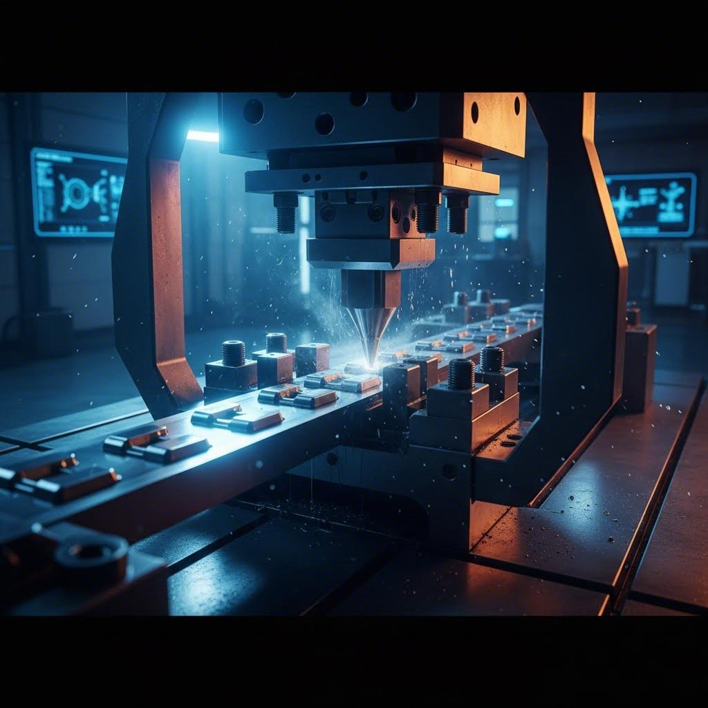
Imagine a manufacturing process so efficient that it transforms a simple metal strip into a precision-engineered component with every single press cycle. That's exactly what the progressive die stamping process delivers—and it's the reason this method has become the backbone of high-volume manufacturing since its development in the 1950s.
Progressive die stamping is a metalworking process where a strip of sheet metal advances through multiple sequential stations within a single die, with each station performing a specific operation—such as cutting, bending, or forming—until a finished part emerges at the end of the line.
Think of it like an assembly line compressed into one powerful machine. The metal strip feeds continuously through the stamping dies, and with each stroke of the press, every station simultaneously performs its designated task. The result? One or more completed parts produced per cycle, with remarkable consistency and speed.
What Makes Progressive Die Stamping Different from Other Methods
You might wonder what sets progressive stamping apart from other metal forming techniques. The answer lies in its unique combination of efficiency and complexity handling.
Unlike compound dies that perform multiple operations in a single stroke at one location, progressive die metal stamping excels at producing intricate parts requiring numerous sequential operations. Each station in the die handles one specific task, allowing manufacturers to create components with complex geometries, tight tolerances, and multiple features—all within a highly automated workflow.
Here's an example of stamping efficiency: while traditional stage tooling might require moving parts between separate machines, progressive dies keep the workpiece connected to the metal strip throughout the entire process. This eliminates handling between operations and dramatically reduces cycle times.
The Core Principle Behind Strip Progression
The magic happens through continuous strip feeding. A coil of flat metal stock enters the stamping press, where specialized feeders advance it precisely with each press stroke. As the strip moves through the die, it encounters stations designed for specific operations—punching pilot holes, piercing features, forming shapes, and eventually cutting off the finished component.
This process dominates precision manufacturing for compelling reasons:
- High production rates suitable for volumes exceeding 50,000 pieces annually
- Exceptional consistency since each part follows the identical path through the same tooling
- Cost efficiency through minimized setup time and reduced material waste
- Complex part capability with tight tolerances maintained throughout production
Industries ranging from automotive to aerospace rely on this method because it delivers precisely what high-demand manufacturing requires: durability, precision, and repeatability at scale. In the sections ahead, you'll discover exactly how each station functions, what components make up a progressive die, and how to determine if this process fits your manufacturing needs.
The Complete Station-by-Station Process Breakdown
Now that you understand the fundamentals, let's pull back the curtain on what actually happens inside a progressive stamping die. Picture the metal strip as it enters the press—it's about to undergo a carefully choreographed sequence of transformations, with each station building upon the work of the previous one.
What makes progressive dies so effective is this sequential precision. Every operation occurs at exactly the right moment, in exactly the right location, creating parts with consistency that manual processes simply cannot match.
From Blanking to Cutoff - Each Station Explained
The journey through a progressive die follows a logical sequence designed to maintain strip integrity while progressively shaping the final component. Here's how each station contributes to the finished part:
- Pilot Hole Piercing – The very first operation typically punches pilot holes into the strip. These aren't part of the final component—they serve as precision reference points that guide the strip through every subsequent station. Without accurate pilot holes, the entire die processing sequence falls apart.
- Blanking – This cutting operation removes excess material from around the part profile. The stamping die punches shear through the metal, creating the rough outline while the workpiece remains attached to the carrier strip. Think of it as sketching the part's silhouette in metal.
- Piercing – Internal features get their moment here. Holes, slots, and cutouts are punched through the material using precisely ground punches. The progressive punch action creates clean edges when clearances between punch and die are properly maintained—typically 5-10% of material thickness per side.
- Forming – Now the flat blank begins taking three-dimensional shape. Forming stations use carefully contoured punches and dies to create bends, ribs, embosses, and contours. The material flows rather than separates, giving the part depth and structural features.
- Bending – Angular features are created here, with the metal folding along precise lines. Bend radii must be carefully calculated based on material type and thickness to prevent cracking. Most materials require a minimum bend radius equal to the stock thickness.
- Coining – When ultra-tight tolerances or specific surface finishes are required, coining applies tremendous pressure to flow metal into exact shapes. This cold-working operation can achieve tolerances as tight as ±0.001 inches on critical dimensions.
- Cutoff – The final station separates the completed part from the carrier strip. This operation must be timed perfectly to release the finished component while allowing the remaining strip skeleton to exit the die cleanly.
Not every progressive die includes all these operations, and many dies combine multiple functions at single stations. The specific sequence depends entirely on part geometry and dimensional requirements.
How Pilot Pins Maintain Micron-Level Precision
Ever wonder how a metal strip traveling through multiple stations at high speed maintains positioning accuracy measured in thousandths of an inch? The answer lies in the pilot pin system—the unsung hero of die stamping precision.
Here's how it works: at the beginning of the die, piercing punches create pilot holes at precisely spaced intervals along the strip edges. As the strip advances to each subsequent station, hardened pilot pins descend into these holes before any cutting or forming begins. These pins physically lock the strip into exact position, compensating for any accumulated feed error or strip distortion.
The mechanics are elegantly simple but critically important:
- Initial engagement – Bullet-nosed pilot tips guide the strip into position as the press closes
- Final registration – Cylindrical pilot shanks lock into the holes with minimal clearance (typically 0.0005-0.001 inches)
- Station coordination – Multiple pilots at each station ensure both longitudinal and lateral positioning
This registration system allows stamping die components to maintain tolerances even when running at speeds exceeding 1,000 strokes per minute. Without precise piloting, feature-to-feature dimensions would drift unacceptably within just a few parts.
Bypass notches play a supporting role in strip control by providing relief areas that prevent overfeeding and accommodate slight variations in coil width or edge camber. These small cutouts along the strip edges allow the material to settle properly against the die's guide rails before pilots engage, ensuring consistent positioning throughout the production run.
Understanding this station-by-station progression reveals why progressive dies demand such precise engineering—and why the tooling architecture behind them matters just as much as the operations themselves.
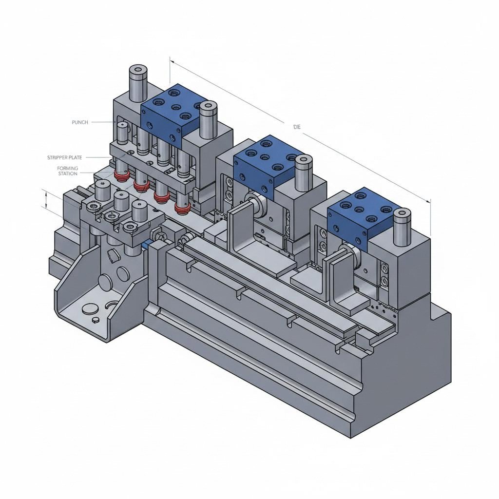
Progressive Die Components and Tooling Architecture
So what exactly makes up the hardware inside a progressive die? Understanding the individual components helps you appreciate how they work together as an integrated system—and why progressive die tooling requires such precise engineering.
Think of a progressive die as a carefully orchestrated machine where every component has a specific job. When one element fails or wears, the entire system feels the impact. Let's break down what's inside.
Essential Die Components and Their Functions
Every die in progressive stamping contains foundational elements that must work in perfect harmony. Here's what you'll find when you examine the architecture of metal stamping dies:
| Component Name | Function | Typical Materials |
|---|---|---|
| Die Shoe (Upper & Lower) | Provides the structural foundation that holds all other components; maintains alignment between upper and lower die halves | Cast iron (G2500/NAAMS), steel plate |
| Punch Plate | Secures and positions all cutting and forming punches; transmits press force to the tooling | A2 or D2 tool steel, hardened to 58-62 HRC |
| Stripper Plate | Holds material flat during cutting; strips the workpiece off punches after each stroke | A2 tool steel, hardened; sometimes spring-loaded |
| Die Block | Contains the female cutting profiles and forming cavities; provides the cutting edge that works with punches | D2/SKD11 for thinner stock; A2/DC53 for thicker materials |
| Pilots | Register and position the strip precisely at each station before operations begin | Hardened tool steel with 20° conical tips |
| Punches | Perform cutting, piercing, and forming operations; create holes and features in the workpiece | M2 high-speed steel, carbide for high-wear applications |
| Forming Stations | Shape material through bending, drawing, and coining operations; create three-dimensional features | D2 for forms; carbide inserts for stainless steel |
| Guide Pins & Bushings | Maintain precise alignment between upper and lower die shoes throughout the press stroke | Hardened steel pins with bronze or ball-cage bushings |
Beyond these core elements, progressive die components often include nitrogen springs for controlled pressure, stock guides that direct strip travel, and sensor systems that detect misfeeds or slug buildup. According to Dramco Tool, most die components are made from hardened tool steel because it's durable and can hold a sharp edge for cutting operations.
Tooling Materials and Hardness Requirements
Choosing the right stamping tooling materials isn't just about durability—it directly impacts part quality, tool life, and maintenance frequency. Here's what drives material selection:
- Cutting punches and dies require maximum hardness (58-62 HRC) to maintain sharp edges through millions of cycles
- Forming sections need toughness to resist cracking under repeated impact, typically hardened to 54-58 HRC
- High-wear applications like stamping stainless steel benefit from carbide inserts or TiN coatings that extend service life
- Structural components prioritize rigidity over hardness, using cast iron or medium-carbon steel
The relationship between workpiece material and tooling selection matters significantly. When you're stamping high-strength steel or abrasive materials, standard D2 tool steel might wear too quickly. That's when engineers specify carbide inserts or apply specialized coatings to extend tool life.
For progressive tooling design, engineers must also consider thermal expansion. During high-speed production, friction generates heat that causes components to expand. Proper clearances and cooling provisions prevent binding and premature wear.
How Engineers Plan Strip Layout and Operation Sequences
Before any steel gets cut, progressive die design begins with strip layout—the blueprint that determines how the part develops through each station. This planning phase is where efficiency gets built into the process.
Engineers consider several factors when designing strip layouts:
- Material utilization – Arranging parts to minimize scrap; some layouts achieve utilization rates above 85%
- Operation sequencing – Placing forming operations after piercing to prevent hole distortion
- Station balance – Distributing forces evenly to prevent die deflection and uneven wear
- Carrier strip integrity – Maintaining enough material between parts to support the strip through all stations
The sequence of operations follows logical principles. Pilot holes always come first. Cutting operations that remove material generally precede forming operations that shape it. Coining and sizing happen near the end when features need final dimensioning. The cutoff station is always last.
Computer-aided design software allows engineers to simulate strip progression before building any tooling. This virtual validation identifies potential problems—like interference between operations or insufficient material flow—long before expensive tool steel gets machined.
Understanding how these components integrate helps you appreciate why die in progressive stamping applications demands such precise coordination. With the tooling architecture clear, the next consideration becomes which materials these dies can actually process—and what specifications each material demands.
Material Selection and Technical Specifications
Now that you understand the tooling architecture, here's the practical question: which metals actually work well in sheet metal stamping dies? The answer depends on formability characteristics, your tolerance requirements, and production speed demands.
Not every metal behaves the same way under the intense pressures of progressive stamping. Some materials flow beautifully through forming stations while others fight back with springback and work hardening. Choosing the right material upfront prevents costly tooling modifications and quality issues down the line.
Metal Selection Criteria for Progressive Stamping
When engineers evaluate materials for the metal stamping manufacturing process, they consider several interrelated factors:
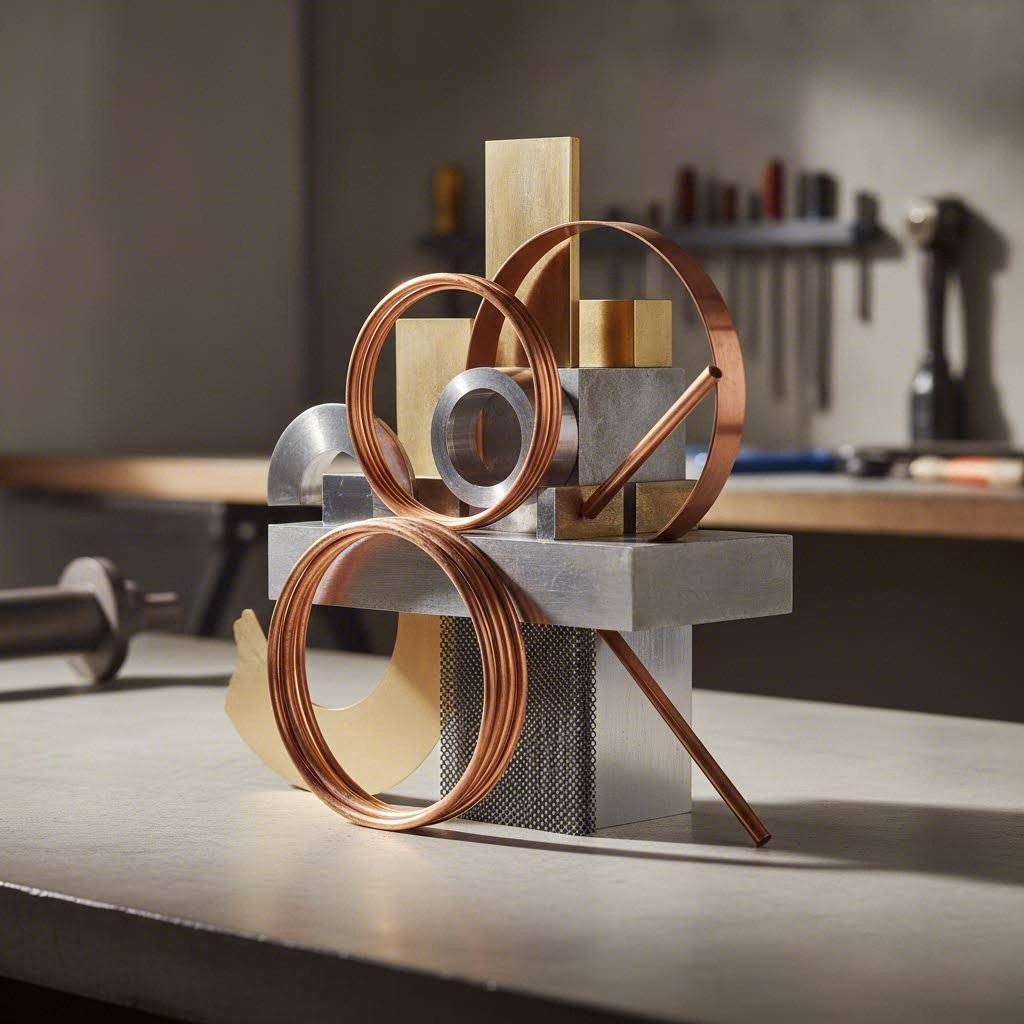
- Formability – How easily does the material bend and stretch without cracking? Ductile metals like copper and aluminum tolerate complex forms better than high-strength steels.
- Work hardening rate – Some materials strengthen dramatically as they're deformed, requiring more press force at later stations. Stainless steel is notorious for this behavior.
- Springback tendency – Elastic recovery after forming affects dimensional accuracy. Higher-strength materials spring back more, demanding overbend compensation in die design.
- Surface finish requirements – Soft materials like brass produce excellent cosmetic surfaces, while harder materials may need additional finishing operations.
- Tool wear impact – Abrasive materials accelerate punch and die wear, increasing maintenance frequency and tooling costs.
Let's examine how specific materials perform in progressive precision metal stampings applications.
Carbon steel remains the workhorse of carbon steel progressive stamping operations. Low-carbon grades (1008-1020) offer excellent formability and consistent behavior. They accept tight bends, hold formed shapes well, and provide predictable tool life. Medium-carbon grades add strength but sacrifice some formability.
Stainless steel presents more challenges. Austenitic grades (304, 316) work harden rapidly, requiring higher tonnage and more robust tooling. However, their corrosion resistance makes them essential for medical and food-processing applications. Expect slower press speeds and more frequent sharpening cycles.
Aluminum stamps easily due to its softness but demands careful attention to galling prevention. Specialized coatings on tooling surfaces help aluminum flow without sticking. Its light weight makes it popular for aerospace and automotive weight-reduction initiatives.
Copper excels in copper progressive stamping for electrical components. Its exceptional conductivity combined with excellent formability makes it ideal for terminals, contacts, and bus bars. Copper flows smoothly through forming stations and produces clean-cut edges.
Brass offers a compelling combination for brass progressive stamping applications requiring both appearance and formability. Decorative hardware, connectors, and plumbing fittings benefit from brass's machinability and attractive finish.
Thickness Ranges and Tolerance Capabilities by Material
Material thickness directly influences what tolerances you can achieve and how fast you can run the press. Here's a comprehensive comparison:
| Material Type | Typical Thickness Range | Formability Rating | Common Applications |
|---|---|---|---|
| Low-Carbon Steel | 0.15mm – 6.0mm | Excellent | Automotive brackets, structural components, appliance parts |
| Stainless Steel (300 Series) | 0.1mm – 3.0mm | Good (work hardens) | Medical devices, food equipment, marine hardware |
| Aluminum (5000/6000 Series) | 0.2mm – 4.0mm | Very Good | Heat sinks, enclosures, aerospace components |
| Copper (C110/C101) | 0.1mm – 3.0mm | Excellent | Electrical terminals, bus bars, RF shielding |
| Brass (C260/C360) | 0.15mm – 2.5mm | Excellent | Connectors, decorative hardware, plumbing fittings |
| High-Strength Low-Alloy Steel | 0.5mm – 4.0mm | Moderate | Structural automotive, safety-critical components |
Tolerance capabilities vary with both material and thickness. Thinner materials (under 1.0mm) typically achieve dimensional tolerances of ±0.05mm on blanked features and ±0.1mm on formed dimensions. Thicker stock loosens these numbers slightly due to increased springback and material flow variation.
Press speed considerations also depend on material behavior. Soft, ductile materials like copper and aluminum can run at speeds exceeding 600 strokes per minute on thin stock. Stainless steel often requires slower speeds—sometimes below 200 strokes per minute—to prevent work hardening issues and allow proper lubrication.
Understanding these material-specific behaviors helps you specify the right combination of material grade, thickness, and tolerance requirements. With material selection covered, the next logical question becomes how progressive die stamping compares to alternative methods—and when each approach makes the most sense.
Progressive Die vs Transfer Die vs Compound Die Stamping
With a solid understanding of materials and their behaviors, you're likely wondering: is progressive die stamping always the right choice? The honest answer is no. While progressive stamping dies dominate high-volume production, two alternative methods—transfer die stamping and compound die stamping—excel in situations where progressive tooling falls short.
Choosing the wrong method can mean wasted tooling investment, excessive scrap, or production bottlenecks. Let's break down when each approach makes sense so you can match the process to your specific requirements.
Progressive vs. Transfer Die Stamping Decision Matrix
Both progressive and transfer die stamping handle complex parts, but they take fundamentally different approaches to moving workpieces through the forming sequence.
In transfer stamping, individual blanks are mechanically or manually transferred from one stamping station to the next. Unlike progressive dies where the part stays connected to the carrier strip, transfer press stamping separates each blank before forming operations begin. Think of it as an assembly line where robotic fingers or mechanical grippers move parts between stations.
When does transfer stamping win? Consider these scenarios:
- Large part sizes – Transfer dies handle components too big to remain attached to a strip. Automotive body panels and large appliance housings often require this approach.
- Deep draws – Parts requiring significant depth benefit from the independent handling that transfer stamping provides.
- Complex orientations – When parts need rotation or repositioning between operations, transfer mechanisms offer flexibility that strip-fed processes cannot match.
Progressive stamping dies counter with their own advantages:
- Higher speeds – Without transfer mechanisms to synchronize, progressive dies typically run faster.
- Lower per-part costs – At high volumes, the simplified material flow reduces handling expenses.
- Tighter tolerances – Continuous strip registration through pilot pins maintains positioning accuracy.
The decision often comes down to part size and geometry. If your component fits within typical strip widths (generally under 300mm) and doesn't require extreme forming depths, progressive tooling usually wins on economics.
When Compound Dies Outperform Progressive Dies
Compound die stamping takes a completely different approach. Instead of sequential stations, a compound die performs multiple operations—typically cutting and piercing—in a single press stroke at one location.
Imagine punching a washer: the outer diameter blanks while the center hole pierces simultaneously. That's compound die and stamping efficiency in action.
Compound dies shine in specific situations:
- Flat, simple parts – Washers, gaskets, and basic blanks with holes don't need multiple forming stations.
- Tight flatness requirements – Single-stroke operations minimize the warping that can occur when parts travel through multiple stations.
- Lower volumes – Simpler tooling means lower upfront investment, making compound dies cost-effective for shorter production runs.
- Maximum material utilization – Compound dies can nest parts efficiently, reducing scrap compared to progressive layouts with carrier strips.
However, compound dies hit their limits quickly. They struggle with three-dimensional features, multiple bends, or parts requiring sequential forming operations. For anything beyond basic flat parts, progressive or transfer methods become necessary.
Comprehensive Process Comparison
Here's how all three methods stack up across the critical decision factors:
| Criteria | Progressive Die Stamping | Transfer Die Stamping | Compound Die Stamping |
|---|---|---|---|
| Part Complexity | High – handles multiple operations including bending, forming, and coining | Very High – accommodates complex shapes, deep draws, and orientation changes | Low – limited to flat parts with basic cut/pierce features |
| Volume Suitability | High volume (50,000+ annually) – optimized for continuous production | Medium to high volume – versatile for both short and long runs | Low to medium volume – economical for simpler production needs |
| Material Utilization | Moderate (70-85%) – carrier strip creates inherent scrap | Good (75-90%) – individual blanks allow efficient nesting | Excellent (85-95%) – optimal nesting without carrier strip waste |
| Tooling Cost | High initial investment – complex multi-station design | Higher – includes transfer mechanisms and multiple stations | Lower – simpler single-station construction |
| Cycle Time | Fast – 200-1,500+ strokes per minute depending on complexity | Moderate – transfer mechanisms limit maximum speed | Moderate – single-stroke but limited to one part per cycle |
| Setup Time | Minimal once installed – continuous coil feeding | Longer – requires calibration of transfer mechanisms | Quick – simpler tooling means faster changeovers |
| Best Applications | Electrical contacts, brackets, connectors, precision components | Large panels, deep-drawn housings, complex automotive parts | Washers, gaskets, simple blanks, laminations |
According to Larson Tool, progressive dies demand regular maintenance due to their intricate structure, while compound dies require less upkeep because of their simpler design. Transfer dies fall somewhere in between, with additional maintenance needs for their transfer mechanisms.
The bottom line? Let your part requirements drive the decision. Start by evaluating part complexity, then consider production volume, and finally factor in tooling budget constraints. Most manufacturers find that progressive dies deliver the best value for medium-complexity parts at high volumes—but transfer and compound methods each have their place in a comprehensive die and stamping strategy.
Understanding these process differences sets the stage for exploring where each method gets applied in real-world manufacturing—from automotive assembly lines to precision medical device production.
Industry Applications from Automotive to Medical Devices
Now that you understand when progressive stamping outperforms alternative methods, let's explore where this process delivers the most value. The industries relying on progressive die stamping share common demands: tight tolerances, consistent quality across millions of parts, and production schedules that leave zero room for variability.
What makes progressive stamping the go-to choice for these sectors? It comes down to matching the process advantages—speed, repeatability, and precision—with industry-specific requirements that other fabrication methods simply cannot meet.
Automotive Applications and OEM Requirements
Walk through any modern vehicle, and you'll encounter dozens of progressive stamped automotive parts without even realizing it. From the moment you insert your key to the structural components keeping you safe, this process shapes the automotive industry's most demanding applications.
Why does automotive components progressive stamping dominate this sector? According to Wedge Products, automotive component manufacturers rely on high-volume stamping partners who can meet demanding schedules and strict tolerances. Progressive stamping excels at producing components that must withstand vibration, heat, and continuous mechanical loading.
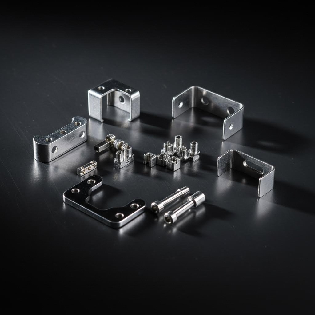
Common automotive applications include:
- Structural brackets and reinforcements – Load-bearing components requiring consistent material properties and dimensional accuracy across production runs spanning years
- Electrical connectors and terminals – Precision contacts for sensors, lighting systems, and electronic control modules demanding tight tolerances on contact surfaces
- Seat frame components – Complex formed parts combining multiple bends, holes, and mounting features in a single progressive die sequence
- Door hardware and latching mechanisms – Components requiring both functional precision and cosmetic surface quality
- HVAC system brackets and sensor plates – Parts that must maintain dimensional accuracy despite temperature cycling and vibration exposure
OEM progressive stamping demands more than just part production—it requires traceability, statistical process control, and the ability to maintain identical specifications across multi-year vehicle platforms. A part produced today must match one produced three years from now for service and replacement purposes. Progressive steel and other materials processed through properly maintained tooling deliver this consistency reliably.
Aerospace and Defense Applications
When failure isn't an option, aerospace manufacturers turn to progressive stamping for components where weight, precision, and reliability intersect. The process advantages align perfectly with aerospace requirements:
- Precision fastener components – Washers, retaining clips, and mounting hardware meeting AS9100 quality standards
- Electrical shielding – EMI/RFI protection components requiring consistent coverage and conductivity
- Structural brackets – Weight-optimized parts using aluminum and titanium alloys
- Connector housings – Complex formed enclosures protecting critical electrical connections from harsh environments
High volume stamping capabilities become critical for aircraft production, where a single platform might require millions of small stamped components over its lifecycle. The dimensional consistency inherent to progressive tooling ensures every fastener, every bracket, and every connector performs identically across the entire fleet.
Precision Requirements in Electronics and Medical Stamping
Electronics and medical device manufacturing push progressive stamping to its precision limits. These industries demand tolerances measured in thousandths of an inch—and they need those tolerances maintained across production volumes that can reach tens of millions annually.
Electronics applications leverage the process for components where electrical performance depends on precise geometry:
- Lead frames – The stamped metal structures that carry semiconductor chips, requiring micron-level accuracy for wire bonding surfaces
- Connector terminals – Contact elements where slight dimensional variations affect signal integrity and mating force
- RF shielding cans – Enclosures providing electromagnetic protection while maintaining tight dimensional tolerances for circuit board mounting
- Battery contacts – Spring elements requiring controlled force characteristics across temperature ranges
- Heat sinks – Formed aluminum components with precise fin geometries for thermal management
Medical progressive stamping presents unique challenges combining precision with regulatory compliance:
- Surgical instrument components – Stainless steel parts requiring burr-free edges and consistent surface finish
- Implantable device housings – Titanium and specialty alloy components meeting biocompatibility requirements
- Diagnostic equipment parts – Precision brackets and mounting components for imaging and testing equipment
- Disposable device components – High-volume stamped parts for single-use medical products where cost-per-piece matters critically
What makes progressive stamping the preferred choice across these demanding applications? The combination of process stability, high production rates, and in-die quality control. When components arrive assembly-ready without secondary operations or rework, manufacturers can focus on final device integration rather than incoming inspection bottlenecks.
Whether you're producing automotive brackets, aerospace fasteners, or medical device housings, the progressive die stamping process delivers what modern manufacturing demands: consistent quality at scale, every single cycle. However, achieving this consistency requires proper quality control and understanding common defects—which brings us to the troubleshooting perspective that separates good production from great production.
Quality Control and Defect Prevention Strategies
Even the most precisely engineered progressive die produces defective parts when something goes wrong. The difference between occasional quality issues and chronic production problems often comes down to understanding why defects occur—and catching them before they cascade into scrapped parts and costly downtime.
What separates experienced stamping engineers from novices? They recognize defect patterns early and trace them back to root causes. Let's examine the most common issues you'll encounter when operating a die-stamping machine and the practical solutions that keep production running smoothly.
Common Progressive Stamping Defects and Root Causes
Every defect tells a story about what's happening inside your tooling. When you understand these patterns, troubleshooting becomes systematic rather than guesswork.
Burring ranks among the most frequent complaints. Those raised metal edges on die stamped parts create assembly problems and safety hazards. According to Dr. Solenoid, burrs typically appear when the cutting edge gap between punch and die becomes excessive—usually beyond 12% of material thickness per side—or when cutting edges dull from wear.
Material springback frustrates engineers because bent features don't hold their intended angles. The material's elastic properties cause it to partially return toward its original flat state after forming. High-strength steels and stainless alloys exhibit the worst springback behavior, sometimes requiring 3-5 degrees of overbend compensation.
Misalignment issues manifest as inconsistent hole positions, uneven trim lines, or features that drift from station to station. When pilot pins wear or strip guides loosen, positioning accuracy suffers immediately. You'll notice tolerance drift within just a few hundred cycles.
Slug pulling occurs when cut-out material sticks to the punch face instead of dropping through the die opening. This creates double-hits on subsequent strokes, damaging both parts and tooling. Insufficient die clearance, vacuum effects, or worn slug retention features typically cause this problem.
Die wear patterns develop predictably but cause progressive quality degradation. Cutting edges round over, forming radii enlarge, and surface finishes deteriorate. Left unchecked, wear accelerates as damaged tooling creates higher stresses on remaining sharp edges.
Here's a comprehensive troubleshooting guide for precision die stamping operations:
| Defect Type | Common Causes | Prevention Methods | Corrective Actions |
|---|---|---|---|
| Excessive Burrs | Worn cutting edges; improper punch-to-die clearance (too large or too small); dull tooling | Maintain clearance at 8-12% of material thickness; schedule regular edge inspections every 50,000 strokes | Regrind cutting edges; adjust clearance; replace worn inserts; consider zero-gap blanking for copper terminals |
| Springback | Material elastic recovery; insufficient overbend; improper forming radius | Use CAE simulation to predict springback; design overbend compensation into tooling; consider coining operations | Modify bend angles 2-5 degrees beyond target; add shaping stations; adjust blank holder force |
| Misalignment | Worn pilot pins; loose guide components; feed inconsistency; die shoe deflection | Inspect pilots regularly; maintain tight guide clearances; verify press parallelism quarterly | Replace worn pilots; retighten guide assemblies; recalibrate feed system; check and correct die shoe flatness |
| Slug Pulling | Vacuum effect in punch face; insufficient die clearance; worn slug retention features; improper lubrication | Use Jektole-style punches with slug ejection pins; maintain proper die clearance; apply consistent lubrication | Add spring-loaded ejector pins; increase die relief angles; apply anti-slug pulling coatings to punch faces |
| Cracking | Insufficient material ductility; too-small bend radii; excessive drawing ratio; work hardening | Verify material properties match specifications; design bend radii ≥4x material thickness; limit drawing depth | Add intermediate annealing; increase forming radii; use multi-stage drawing; preheat high-strength materials |
| Surface Scratches | Rough die surfaces; foreign particles; inadequate lubrication; damaged stripper plates | Polish die surfaces to Ra 0.2μm or better; filter lubricant systems; clean dies between runs | Repolish affected surfaces; apply chrome plating or TD treatment; replace damaged components; use nylon pressure plates for aluminum |
| Wrinkling | Insufficient blank holder pressure; excessive material flow; improper draw bead design | Optimize blank holder force using servo hydraulic control; design appropriate draw beads | Increase blank holder pressure; add or modify draw beads; adjust material flow paths |
Preventive Maintenance Strategies for Die Longevity
Waiting for defects to appear before taking action guarantees production interruptions. Smart stamping die maintenance follows a proactive schedule based on stroke counts, material abrasiveness, and historical wear patterns.
Here's what effective maintenance programs include:
- Stroke-based inspection intervals – Check cutting edges every 50,000 strokes for standard materials; reduce to 25,000 strokes for stainless steel or abrasive alloys
- Sharpening schedules – Regrind punches and dies before edge breakdown causes burr problems; removing 0.1-0.2mm typically restores cutting performance
- Lubrication monitoring – Verify lubricant delivery and coverage; contaminated or depleted lubricant accelerates wear dramatically
- Alignment verification – Measure pilot pin wear and guide bushing clearances; replace components before tolerances exceed acceptable limits
- Surface condition tracking – Document forming surface conditions with photos; compare against baseline to identify progressive wear
According to Franklin Fastener, regular maintenance and tool sharpening extend the life of stamping dies significantly. Additionally, using tool coatings—such as TiAlN or TiN—on high-wear components can double or triple service life between regrinds.
Modern stamping technology incorporates in-die sensors that monitor forming forces, strip position, and component presence in real-time. These systems detect anomalies before they produce defective parts, enabling immediate corrective action. When a sensor detects abnormal force patterns, the press stops before damage occurs.
Establishing a die life record for each tool helps predict maintenance needs based on actual performance rather than arbitrary schedules. Track stroke counts, material grades processed, defect incidents, and maintenance actions. Over time, patterns emerge that allow you to optimize maintenance timing for maximum tool life with minimum quality risk.
Understanding types of stamping dies and their specific wear characteristics helps you tailor maintenance approaches appropriately. Progressive dies with many stations require more comprehensive inspection protocols than simpler compound tools. Focus attention on stations that see the highest forming stresses or process the most abrasive materials.
With quality control fundamentals covered, the next step is understanding how to design parts that manufacture successfully from the start—and how to evaluate the tooling investment required for your production needs.
Design Guidelines and Tooling Investment Analysis
You've seen how progressive dies work, what defects to watch for, and where the process excels. Now comes the practical question every manufacturing engineer faces: how do you design parts that actually stamp well—and how do you justify the tooling investment to finance?
Getting these fundamentals right at the design stage prevents costly tooling modifications later. The decisions you make on paper directly impact what happens on the press floor, so let's walk through the guidelines that separate smooth production launches from expensive redesign cycles.
Design for Manufacturability Guidelines
Experienced progressive die manufacturers will tell you that 80% of production problems originate in part design—not tooling or press setup. Following proven DFM principles during the design phase dramatically reduces development risk and accelerates time-to-production.
Here's your essential DFM checklist for metal stamping die design:
- Minimum hole diameter – Specify holes no smaller than 1.0x material thickness for standard punches; smaller features require specialized tooling and increase maintenance frequency
- Hole-to-edge distance – Maintain at least 1.5x material thickness between hole edges and part edges; closer spacing causes distortion during blanking and weakens the remaining material
- Hole-to-hole spacing – Keep minimum distance between holes at 2x material thickness; tighter spacing creates thin webs that distort under forming pressure
- Bend radii requirements – Design inside bend radii at minimum 1x material thickness for ductile materials like copper and aluminum; specify 2x thickness or greater for high-strength steel and stainless grades
- Bend-to-edge distance – Position bend lines at least 2.5x material thickness from edges to prevent cracking and distortion
- Bend-to-hole distance – Allow minimum 2.5x material thickness between bend lines and hole edges; closer features experience distortion during forming
- Relief notches – Include corner relief at intersecting bends to prevent tearing; radius should equal material thickness minimum
- Uniform wall thickness – Maintain consistent material thickness throughout the part; avoid designs requiring significant material thinning during forming
- Draft angles on forms – Include 1-3° draft on vertical walls of drawn features to facilitate part ejection
- Grain direction consideration – Orient major bends perpendicular to material grain direction when possible; parallel bends risk cracking, especially in high-strength materials
According to Fictiv, standard blanking and forming operations typically achieve tolerances of ±0.005 inches (±0.127 mm), while specialized equipment like fineblanking can hold critical features to ±0.001 inches (±0.025 mm). Design your tolerance specifications around these capabilities to avoid unnecessary precision requirements that drive up tooling costs.
Tooling Investment and ROI Considerations
Progressive tool and die investments represent significant capital expenditure—but the economics become compelling at the right production volumes. Understanding the cost structure helps you build a business case that finance teams can approve.
According to Shaoyi's automotive stamping cost analysis, tooling costs range dramatically based on complexity:
- Simple blanking dies – $5,000 to $15,000 for basic cut-and-pierce operations
- Moderate complexity progressive dies – $15,000 to $50,000 for parts requiring 5-10 stations with forming operations
- Complex progressive dies – $50,000 to $100,000+ for intricate parts with 15+ stations, tight tolerances, and demanding geometries
These upfront numbers look substantial, but the math changes dramatically when you calculate cost per part. Consider a $60,000 progressive die producing 200,000 parts annually over five years. The tooling contribution drops to just $0.06 per part—negligible compared to material and processing costs. That same die producing only 5,000 parts adds $12.00 per unit, potentially making the project unviable.
The break-even calculation follows this logic:
Break-even Volume = Tooling Investment ÷ (Alternative Cost Per Part - Progressive Die Cost Per Part)
For most applications, progressive stamping die design becomes economical somewhere between 10,000 and 50,000 annual units—though exact thresholds depend on part complexity and alternative manufacturing methods.
Lead Time Expectations and Development Risk
Typical progressive die development follows this timeline:
- Design and engineering – 2-4 weeks for strip layout development and die design
- Tool construction – 8-16 weeks depending on complexity and manufacturer capacity
- Tryout and debugging – 1-3 weeks for initial sampling and adjustments
- PPAP and qualification – 2-4 weeks for automotive applications requiring formal approval
Total timeline from design freeze to production-ready tooling typically runs 14-24 weeks. However, working with stamping tool and die partners who leverage CAE simulation technology can compress this timeline significantly by identifying and resolving forming issues virtually before cutting steel.
CAE simulation provides measurable benefits for stamping die manufacturing projects:
- Springback prediction – Virtual compensation reduces physical tryout iterations
- Formability analysis – Identifies potential cracking or thinning before tooling construction
- Material flow optimization – Validates draw bead and blank holder designs
- Die stress analysis – Ensures tooling survives production forces without premature failure
For manufacturers seeking to minimize development risk, partnering with experienced stamping die manufacturers who offer comprehensive capabilities becomes crucial. Shaoyi's precision stamping die solutions exemplify what to look for in a development partner: IATF 16949 certification for automotive applications, CAE simulation for defect-free results, rapid prototyping capabilities delivering samples in as little as 5 days, and a 93% first-pass approval rate that minimizes costly iteration cycles.
When evaluating potential stamping partners, consider these qualification criteria:
- Simulation capabilities – Can they predict and prevent forming issues before building tooling?
- Prototyping speed – How quickly can they produce sample parts for validation?
- Quality certifications – Do they hold relevant certifications (IATF 16949, AS9100, ISO 13485) for your industry?
- First-pass success rate – What percentage of their tools qualify on initial tryout?
- Press capacity range – Can they handle your tonnage requirements for both prototyping and production?
The lowest quoted tooling price rarely delivers the lowest total cost of ownership. According to Eigen Engineering, CAD and simulation enable engineers to solve issues before production, speeding product development, saving money and time, and reducing the number of prototypes required.
Investing in quality tooling from capable progressive die manufacturers pays dividends throughout the production lifecycle. A well-designed die guaranteed for 1 million+ strikes effectively caps your tooling expenditure while delivering consistent quality across years of production. That predictability—knowing your per-part cost remains stable and your quality stays consistent—represents the true ROI of progressive stamping done right.
With design guidelines and investment analysis covered, you're equipped to make informed decisions about whether progressive die stamping fits your manufacturing needs. The final consideration is weighing these advantages against the process limitations to determine your optimal path forward.
Making the Right Progressive Die Stamping Decision
You've explored the complete progressive die stamping process—from station-by-station operations to tooling architecture, material selection, and quality control strategies. Now comes the critical moment: deciding whether this manufacturing method aligns with your specific project requirements.
Making the right choice requires honest evaluation of both the compelling advantages and real-world limitations. Let's weigh these factors objectively so you can move forward with confidence.
Weighing the Advantages Against Limitations
Progressive die stampings deliver powerful benefits that explain their dominance in high-volume manufacturing. However, the process isn't universally optimal for every application.
Key Advantages
- Exceptional production speed – Running at 200-1,500+ strokes per minute, progressive metal stamping produces finished parts faster than virtually any alternative method
- Outstanding part-to-part consistency – According to Worthy Hardware, the process can hold tolerances as tight as ±0.001" (±0.025mm), ensuring every component performs identically
- Low per-part cost at volume – Once tooling is paid off, the minimal labor involvement and rapid cycle times drive down unit economics dramatically
- Reduced handling and secondary operations – Parts emerge complete from the die, eliminating inter-operation transfers that introduce quality variability
- Complex geometry capability – Multiple operations integrated into a single tool enable intricate features impossible with simpler die types
- Minimal operator dependency – Automated coil feeding and in-die processing ensure consistent quality regardless of shift changes
Key Limitations
- High initial tooling investment – Progressive die & stamping tooling costs range from $15,000 to $100,000+, requiring substantial upfront capital commitment
- Limited design flexibility after production begins – According to industry experts, design changes after tooling construction can be very expensive and time-consuming, sometimes requiring completely new tools
- Material waste from carrier strips – The strip skeleton creates inherent scrap, typically limiting material utilization to 70-85%
- Part size constraints – Components must fit within practical strip widths, generally limiting progressive stamping to parts under 300mm in their largest dimension
- Extended development timeline – Tool design and construction typically requires 14-24 weeks from design freeze to production-ready status
- Volume dependency – The economics only work at sufficient volumes, typically 10,000+ annual units depending on part complexity
The decision ultimately comes down to three primary factors: your production volume requirements, part complexity, and whether your design is finalized. If you're producing high quantities of complex parts with a stable design, progressive stamping almost certainly delivers the best total cost of ownership.
Next Steps for Your Manufacturing Project
Where you go from here depends on your current stage in the manufacturing journey. Here's your roadmap based on where you stand today:
If you're still learning about the progressive stamping process:
- Review the station-by-station breakdown to understand how parts develop through sequential operations
- Study the material selection guidelines to identify compatible metals for your application
- Compare progressive, transfer, and compound die methods to understand which approach best fits your part geometry
If you're evaluating whether progressive stamping suits your project:
- Calculate your annual volume requirements—progressive dies typically become economical above 10,000-50,000 units annually
- Review DFM guidelines against your current part design; features that violate manufacturability principles will require modification
- Estimate break-even volume using your alternative manufacturing costs as the baseline
- Assess whether your design is stable enough to justify tooling investment
If you're ready to implement progressive die stamping:
- Engage with qualified stamping die manufacturers early in the design finalization process
- Request CAE simulation analysis to validate formability before committing to tooling construction
- Establish clear tolerance specifications based on realistic process capabilities
- Develop a maintenance and quality control plan to protect your tooling investment
For manufacturers ready to move from concept to production, partnering with experienced die manufacturers offering end-to-end capabilities streamlines the entire development path. Look for partners who combine comprehensive mold design expertise with high-volume production capacity—this integration eliminates the communication gaps and handoff delays that plague projects split across multiple suppliers.
Shaoyi's stamping die solutions exemplify this integrated approach, delivering everything from initial design through production-ready tooling. Their engineering team brings cost-effective, high-quality tooling tailored to OEM standards, backed by IATF 16949 certification and the simulation capabilities that reduce development risk.
The progressive die and stamping decision isn't just about choosing a manufacturing method—it's about building a foundation for consistent, cost-effective production that scales with your business. Make that decision based on honest evaluation of your requirements, and you'll position your manufacturing operation for long-term success.
Frequently Asked Questions About Progressive Die Stamping
1. What are the 7 steps in the stamping method?
The seven most common metal stamping processes include blanking (cutting the initial shape), piercing (creating internal holes and features), drawing (forming depth into flat material), bending (creating angular features), air bending (controlled angular forming), bottoming and coining (achieving tight tolerances through high pressure), and pinch trimming (removing excess material). In progressive die stamping, these operations occur sequentially across multiple stations within a single die, with pilot hole piercing typically added as the first operation to ensure precise strip alignment throughout the process.
2. What is the difference between progressive and transfer die stamping?
Progressive die stamping keeps the workpiece connected to the carrier strip as it advances through sequential stations within one die, making it ideal for smaller parts at high speeds (200-1,500+ strokes per minute). Transfer die stamping separates individual blanks and mechanically moves them between stations, allowing for larger parts, deep draws, and complex orientations. Progressive dies offer faster cycle times and tighter tolerances through continuous pilot pin registration, while transfer dies excel with oversized components and parts requiring repositioning between operations.
3. What materials work best for progressive die stamping?
Low-carbon steel (1008-1020) remains the most popular choice due to excellent formability and predictable tool life. Copper and brass excel in electrical applications with superior conductivity and smooth forming characteristics. Aluminum offers lightweight advantages but requires anti-galling tooling coatings. Stainless steel works well for corrosion-resistant applications but demands slower press speeds due to rapid work hardening. Material thickness typically ranges from 0.1mm to 6mm, with tolerances of ±0.05mm achievable on thinner stock.
4. How much does progressive die tooling cost?
Progressive die tooling investment varies significantly based on complexity: simple blanking dies range from $5,000-$15,000, moderate complexity dies with 5-10 stations cost $15,000-$50,000, and complex dies with 15+ stations can exceed $100,000. However, when producing high volumes (200,000+ parts annually over five years), tooling contribution drops to just cents per part. Break-even typically occurs between 10,000-50,000 annual units, making progressive stamping economical for sustained high-volume production runs.
5. How do you prevent common progressive stamping defects?
Preventing defects requires proactive maintenance and proper die design. For burrs, maintain punch-to-die clearance at 8-12% of material thickness and inspect cutting edges every 50,000 strokes. Combat springback through CAE simulation and overbend compensation of 2-5 degrees. Prevent misalignment by regularly replacing worn pilot pins and maintaining tight guide clearances. Address slug pulling with Jektole-style punches featuring ejection pins. Implement stroke-based inspection intervals and track die life records to predict maintenance needs before quality issues arise.