 Small batches, high standards. Our rapid prototyping service makes validation faster and easier —

Metal Stamping Manufacturing Process Decoded: From Raw Sheet To Finished Part
What Is Metal Stamping and How Does It Work
So, what is metal stamping exactly? It's a cold-forming industrial process that transforms flat sheet metal into precisely shaped components through controlled force application. Unlike casting or machining, the metal stamping process uses precision dies and high-pressure presses to cut, bend, and form metal without melting it. The tool and die set—consisting of a punch (male component) and die (female component)—work together to shape raw material into finished parts with remarkable accuracy, holding tolerances as tight as ±0.001 inches.
From Flat Sheet to Finished Part
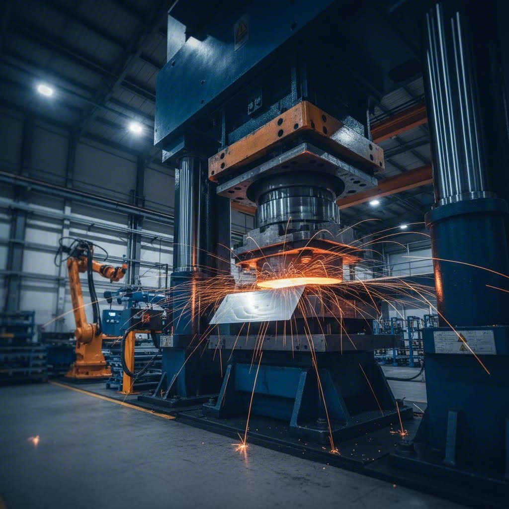
Imagine feeding a flat metal sheet into a powerful press. Within seconds, that sheet emerges as a precisely formed bracket, clip, or complex automotive component. That's the stamping meaning in manufacturing—a rapid transformation process that makes high-volume production both practical and economical.
The stamping process begins when sheet metal (supplied as coils or blanks) is positioned under a metal press. As the press descends with extreme force, the die cuts, bends, or shapes the material into the desired form. What is stamped metal after this process? It's a component that maintains the parent material's strength while gaining its new geometric configuration—all without welding, assembly, or extensive finishing.
The Cold-Forming Advantage
Here's something many overlook: while stamping is classified as a "cold-forming" process, it isn't entirely temperature-neutral. Research shows that friction between the tool and workpiece, combined with plastic deformation of the sheet metal, generates heat that can significantly affect the tribosystem. This temperature rise influences lubricant breakdown, changes the physical properties of tribolayers, and alters material behavior—factors that can impact formability if not properly managed.
Despite this friction-induced heating, metal pressing maintains a critical distinction from die casting: the material never reaches its melting point. This preserves the metal's grain structure and mechanical properties while enabling faster cycle times than processes requiring heating and cooling phases.
Why Manufacturers Choose Stamping Over Alternatives
When comparing manufacturing methods, stamping delivers distinct advantages:
- Speed and Volume: Metal stamping produces large batches of parts quickly and accurately, making it ideal for both short and long production runs
- Precision: CNC programming and computer-aided design deliver consistent, repeatable results with every cycle
- Material Versatility: Aluminum, brass, copper, steel, and stainless steel all work well in stamping applications
- Cost Efficiency: Lower per-part costs compared to machining, especially at higher volumes
What is a stamping operation best suited for? Applications spanning automotive components, electronic housings, aerospace brackets, telecommunications hardware, and domestic appliances. From simple clips to complex multi-bend assemblies, the process adapts to diverse manufacturing needs while maintaining the tight tolerances that precision industries demand.
Types of Stamping Presses and Their Applications
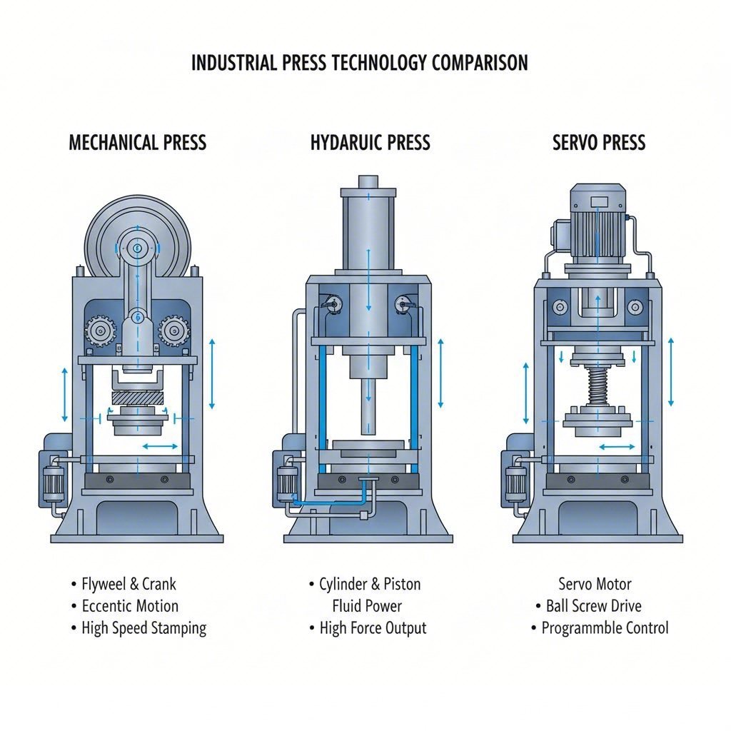
What is a stamping press, and why does the type matter so much? At its core, a stamping press transmits force through a moving ram (or slide) to specific tooling, shaping sheet metal into finished components. However, the mechanism generating that force—mechanical, hydraulic, or servo—dramatically affects production speed, part quality, and operational flexibility. Understanding these differences helps engineers and procurement professionals match equipment to application requirements.
According to SME's training materials, stamping presses range from small benchtop units generating just five tons to massive machines rated in thousands of tons. Press speeds vary from 10-18 strokes per minute up to 1,800 strokes per minute, depending on the press type and application.
Mechanical Presses for High-Speed Production
The traditional mechanical stamping press remains the workhorse of high-volume manufacturing. Here's how it works: an electric motor turns a flywheel that revolves around a crankshaft. When a clutch engages, the flywheel's rotational energy transfers through the drive train to create vertical ram movement.
What makes a steel stamping press excel at speed? The direct drive arrangement—where the motor rotates the flywheel through a belt system—provides the highest stroking rates. A "high-speed mechanical press" typically achieves 300 strokes per minute or higher, with small high-volume parts running as fast as 1,400 strokes per minute.
Key characteristics of mechanical metal stamping presses include:
- Fixed stroke length (though variable-stroke models exist from some manufacturers)
- Full press capacity near bottom dead center of the stroke
- High accuracy and repeatability for consistent part quality
- Simplicity of setup and operation
- Relatively low initial cost compared to servo alternatives
The tradeoff? Mechanical presses achieve maximum force only near the bottom of the ram stroke, and the slide velocity profile within a single cycle remains fixed. This makes them ideal for relatively flat parts with shallower forming requirements—think automotive panels, appliance components, and hardware parts processed through progressive or transfer dies.
Hydraulic Presses for Deep Drawing Control
When your application involves deep, complex forms requiring significant material flow, a hydraulic sheet metal press often becomes the better choice. Unlike mechanical systems, hydraulic presses deliver full tonnage at any point in the stroke—not just near the bottom.
This capability proves essential for parts such as:
- Tanks and cylinders
- Bowl-shaped components
- Parts requiring a "dwell" at the bottom of the stroke
- Complex drawn geometries where material needs time to flow
The hydraulic steel press offers several distinct advantages:
- Variable stroke length adjustable to facilitate part clearance
- Slide motion control throughout the entire stroke range
- Variable slide velocity within a single cycle (typically fast approach, slow press, fast return)
- Full working energy at any speed
- Pre-settable working pressure accommodating different tool heights and material thicknesses
The limitations? Hydraulic stamping presses generally cannot match the cycling speeds of similar-sized mechanical presses, and they typically deliver lower accuracy and repeatability. When production speed isn't the primary concern, however, their versatility for deep drawing and forming operations makes them invaluable.
Servo Technology for Precision Flexibility
What if you need the speed of mechanical presses combined with the flexibility of hydraulic systems? That's precisely where servo press technology shines. These metal stamping presses replace the traditional flywheel, clutch, and brake with high-capacity servo motors, enabling programmable control over stroke, slide motion, position, and speed.
According to Stamtec's technical analysis, servo presses offer production speeds often approaching traditional mechanical presses while providing hydraulic-like versatility. The two primary drive technologies are:
- Link-assisted drives: Cost-effective solutions using standard AC servo motors with link or toggle mechanisms creating mechanical ratios for standard motor sizes
- Direct drive systems: Proprietary high-torque, low-RPM motors designed specifically for press applications
Programmable stroke profiles include cycle, swing, multi-pass, deep drawing, general forming, perforation/blanking, and warm forming modes. With full working energy at any speed and the ability to dwell anywhere in the stroke, servo presses handle drawn and formed parts exceptionally well—though they still achieve full tonnage capacity near the bottom of the stroke like their mechanical counterparts.
Comparing Press Types: A Technical Reference
Selecting the right stamping press requires weighing multiple factors against your specific application. The following comparison helps clarify where each technology excels:
| Criteria | Mechanical Press | Hydraulic Press | Servo Press |
|---|---|---|---|
| Speed Capability | Highest (up to 1,400+ SPM for small parts) | Slowest (10-18 SPM typical) | High (approaches mechanical speeds) |
| Force Control | Full capacity near bottom dead center only | Full capacity at any stroke position | Full capacity near bottom dead center |
| Energy Delivery | Dependent on flywheel mass and speed | Full working energy at any speed | Full working energy at any speed |
| Stroke Flexibility | Fixed (variable available from some manufacturers) | Fully adjustable | Fully programmable |
| Accuracy/Repeatability | High | Lower than mechanical | High |
| Maintenance | Moderate (clutch/brake wear) | Hydraulic system maintenance required | Lower mechanical wear |
| Initial Cost | Relatively low | Relatively low | Relatively high |
| Best Applications | High-volume flat parts, progressive dies | Deep drawing, complex forms, dwell operations | Versatile forming, variable production needs |
The bottom line? Mechanical stamping presses deliver unmatched speed but lack flexibility. Hydraulic machines provide versatility for complex drawing and forming but sacrifice cycle time. Servo presses combine the best characteristics of both—at a higher initial investment. Your optimal choice depends on part geometry, production volumes, accuracy requirements, and budget constraints.
With the right press selected, understanding the specific stamping operations each can perform becomes the next critical step in optimizing your manufacturing process.
Nine Essential Stamping Operations Explained
Now that you understand the presses powering stamping and die cutting operations, let's explore what actually happens when metal meets die. The metal stamping manufacturing process encompasses nine distinct operations—each with unique mechanical actions, material requirements, and precision capabilities. Mastering these fundamentals helps engineers specify the right processes for their applications while setting realistic tolerance expectations.
Cutting Operations - Blanking and Punching Fundamentals
Ever wonder how flat sheets become precisely shaped starting pieces? That's where cutting operations come in. These processes use shearing force to separate material, creating the foundation for subsequent forming operations.
Blanking
Blank stamping metal is typically the first step in creating stamped components. During blanking, the stamping die cuts a flat shape (the "blank") from sheet metal—think of it as a precision cookie cutter for metal. The blank becomes the workpiece for further forming or assembly.
- Mechanical action: A punch descends through the sheet into a matching die cavity, shearing the material along the punch perimeter
- Material thickness range: 0.1 mm to 6 mm (0.004" to 0.25") for most applications
- Tolerance capability: ±0.05 mm to ±0.1 mm for standard blanking operations
- Typical applications: Flat washers, gaskets, structural brackets, base components for progressive die operations
A critical consideration during blanking is burr formation. According to design guidelines from ESI, burr allowance is generally 10% of the sheet thickness. Avoiding sharp corners and complex cutouts minimizes burr severity.
Punching (Piercing)
While blanking focuses on the cut-out piece, punching creates holes and cutouts within a part. The slug (removed material) becomes scrap while the surrounding material remains the workpiece.
- Mechanical action: A punch forces through the sheet, creating holes or cutouts fully enclosed within the part's edges
- Material thickness range: 0.1 mm to 4 mm for standard punching; thicker materials require specialized tooling
- Tolerance capability: ±0.05 mm to ±0.2 mm depending on material thickness
- Design considerations: Minimum hole diameter should be 1.2x material thickness; for stainless steel, use 2x material thickness
Here's an important detail many overlook: punched holes don't have constant profiles through the material thickness. The hole tapers on the bottom side as the punch breaks through, with taper amount relative to the die clearance. If your application requires constant diameter through the entire thickness, secondary drilling or machining becomes necessary.
Forming Operations - Bending, Stretching, and Drawing
Forming operations reshape metal without removing material—transforming flat blanks into three-dimensional components. These processes require careful consideration of material behavior, springback, and dimensional control.
Bending
Bending is perhaps the most common example of stamping in everyday products. This operation creates angular forms by applying force along a linear axis, permanently deforming the material.
- Mechanical action: Material is forced over or into a die, creating a permanent angular change
- Material thickness range: 0.3 mm to 6 mm for most stamping applications
- Tolerance capability: ±1° to ±2° for angle accuracy
- Critical design rule: Bend height must be at minimum 2.5x material thickness plus the bend radius
Material springback represents the primary tolerance challenge in bending. When force is released, the material's elastic deformation causes the bend angle to partially "spring back" toward its original flat state. High-strength materials exhibit more pronounced springback—a factor that must be compensated for in die design.
Stretching
When parts require smooth, curved surfaces without wrinkles, stretching operations deliver results. The material is clamped at its edges while a punch forces it into a die cavity, elongating the metal.
- Mechanical action: Material is stretched over a form, with thickness reduction occurring as the metal elongates
- Material thickness range: 0.5 mm to 3 mm typical; thicker materials risk cracking
- Tolerance capability: ±0.1 mm to ±0.3 mm depending on draw depth and material ductility
- Best suited for: Automotive body panels, appliance housings, components requiring smooth contoured surfaces
Drawing (Deep Drawing)
Deep drawing pushes material into a die cavity to create cup-shaped, cylindrical, or box-shaped components. This stamping example appears in countless products—from beverage cans to motor housings.
- Mechanical action: A blank is held by a blank holder while the punch forces material into the die cavity, creating significant depth relative to width
- Material thickness range: 0.3 mm to 4 mm; wall thickness uniformity becomes challenging with thicker materials
- Tolerance capability: Dimensional tolerances of ±0.05 mm achievable for precision work; complex deep-drawn parts may require ±0.1 mm or looser
- Key consideration: Draw ratio (blank diameter to punch diameter) typically limited to 1.8-2.0 for single operations
Flanging
Flanging creates bent edges at 90 degrees, often on small tabs or around holes. This operation produces attachment features, strengthens edges, or creates mating surfaces.
- Mechanical action: Material is bent perpendicular to the main surface, either inward or outward from the part
- Material thickness range: 0.3 mm to 3 mm for most applications
- Tolerance capability: ±0.1 mm to ±0.2 mm for flange height and position
- Typical applications: Mounting tabs, hole reinforcement, edge stiffening, mating flanges for assemblies
Finishing Operations - Coining, Embossing, and Curling
These operations add precision, detail, and functional features to stamped components. They typically occur after primary cutting and forming operations are complete.
Coining
When your application demands the tightest tolerances and sharpest details, coining steel or other metals delivers results unmatched by other stamping and pressing methods. This high-pressure operation compresses material to create precise features.
- Mechanical action: Extremely high pressure (up to 5-6 times that of other forming operations) compresses material between punch and die, eliminating springback
- Material thickness range: 0.1 mm to 2 mm; thinner materials respond best
- Tolerance capability: Up to ±0.01 mm—among the tightest achievable in stamping
- Typical applications: Coin and medal manufacturing, precision connectors, parts requiring crisp lettering or fine surface detail
Coining also serves a practical purpose beyond detail creation: during the coining process, edges of stamped parts can be struck to flatten or break burrs, creating smoother edges and potentially eliminating secondary deburring operations.
Embossing
Embossing creates raised or recessed designs in sheet metal surfaces without cutting through the material—adding visual interest, functional textures, or identification features.
- Mechanical action: Material is forced into or over a pattern in the die, creating corresponding relief on the surface
- Material thickness range: 0.3 mm to 2 mm for most decorative applications
- Tolerance capability: ±0.1 mm for feature height and position
- Typical applications: Logos and branding, grip textures, decorative patterns, stiffening ribs
Curling
Curling forms rolled edges on sheet metal parts, creating smooth, safe edges while adding structural rigidity. You'll find curled edges on everything from food cans to electrical enclosures.
- Mechanical action: Progressive rolling of material edge into a circular or partial-circular profile
- Material thickness range: 0.3 mm to 1.5 mm typical; thicker materials require larger curl radii
- Tolerance capability: ±0.2 mm for curl diameter and position
- Typical applications: Safety edges, hinge barrels, wire guide channels, structural reinforcement
Grooving
Grooving creates channels or indentations in sheet metal, often for functional purposes such as sealing, alignment, or decorative effect.
- Mechanical action: Material is pressed into linear or curved channels without material removal
- Material thickness range: 0.5 mm to 3 mm depending on groove depth
- Tolerance capability: ±0.1 mm for groove depth and width
- Typical applications: O-ring seats, alignment features, decorative lines, fold guides
Operation Selection Quick Reference
Choosing the right operation—or combination of operations—depends on your part requirements. Here's a practical summary:
| Operation | Primary Function | Thickness Range | Best Tolerance |
|---|---|---|---|
| Blanking | Cut flat shapes from sheet | 0.1-6 mm | ±0.05 mm |
| Punching | Create holes/cutouts | 0.1-4 mm | ±0.05 mm |
| Bending | Create angular forms | 0.3-6 mm | ±1° |
| Stretching | Form smooth curved surfaces | 0.5-3 mm | ±0.1 mm |
| Drawing | Create cup/box shapes | 0.3-4 mm | ±0.05 mm |
| Flanging | Create 90° edge bends | 0.3-3 mm | ±0.1 mm |
| Coining | Precision detail/tolerance | 0.1-2 mm | ±0.01 mm |
| Embossing | Raised/recessed patterns | 0.3-2 mm | ±0.1 mm |
| Curling | Rolled edge formation | 0.3-1.5 mm | ±0.2 mm |
| Grooving | Linear channels/indentations | 0.5-3 mm | ±0.1 mm |
Understanding these nine operations provides the foundation for specifying stamped components effectively. However, knowing individual operations is just the beginning—the real efficiency gains come from understanding how these operations sequence together in a complete manufacturing workflow.
The Complete Metal Stamping Workflow
You've seen the individual operations—but how do they come together in a real production environment? The metal stamping manufacturing process follows a systematic seven-stage workflow, each with specific equipment requirements, quality checkpoints, and decision points that determine whether your project succeeds or struggles. Let's walk through the complete journey from concept to finished component.
Engineering the Blueprint for Success
Every successful stamping manufacturing process begins long before metal touches a die. The design and engineering phase establishes the foundation for everything that follows.
-
Design and Engineering
During this critical first step, engineers translate part requirements into manufacturable designs. Modern stamping technology relies heavily on CAD/CAM software to create detailed 3D models, simulate material flow, and identify potential forming issues before cutting steel.
Key activities include:
- Part geometry optimization for stamping feasibility
- Material specification based on mechanical requirements
- Tolerance analysis and GD&T (Geometric Dimensioning and Tolerancing) definition
- Process simulation using finite element analysis (FEA)
- Design for manufacturability (DFM) review
Quality checkpoint: Design review meeting with tooling engineers to verify formability, identify potential springback issues, and confirm tolerance achievability before tool development begins.
-
Tool and Die Creation
With approved designs in hand, toolmakers begin the die development process. This stage typically consumes the most lead time and investment in any stamping project.
Equipment specifications:
- CNC machining centers with ±0.005 mm positioning accuracy
- Wire EDM machines for complex die profiles and tight clearances
- Surface grinders achieving Ra 0.4 μm or better finish
- Heat treatment furnaces for die steel hardening (typically 58-62 HRC)
Quality checkpoint: First article inspection of die components against CAD models, verification of clearances, and surface finish measurement before assembly.
Die Development and Validation
-
Material Selection and Preparation
Choosing the right material—and preparing it properly—directly impacts every downstream operation in the sheet metal stamping process.
Preparation activities include:
- Incoming material inspection (thickness verification, surface condition, mechanical property testing)
- Coil slitting to required width (±0.1 mm typical)
- Leveling to remove coil set and crossbow
- Lubricant application (draw compounds, oils, or dry-film lubricants)
Quality checkpoint: Pre-fabrication inspection verifies raw materials have the properties necessary to meet part specifications. This includes tensile testing, hardness verification, and surface inspection for defects.
-
Press Setup and Validation
Proper press setup transforms good tooling into good parts. This stage configures the stamping press for optimal performance with the specific die set.
Setup parameters include:
- Shut height adjustment (±0.05 mm precision)
- Stroke length and speed programming
- Feed progression and pilot timing (for progressive dies)
- Tonnage monitoring and overload protection settings
- Lubrication system calibration
Quality checkpoint: Trial runs with dimensional verification before production release. First-piece approval documents critical dimensions against specifications.
From Raw Coil to Finished Component
-
Stamping Execution
Production stamping represents the heart of the manufacturing stamping process. Here, raw material transforms into formed components at rates ranging from single pieces per minute to over 1,000 strokes per minute.
Process monitoring includes:
- Real-time tonnage signature analysis
- In-die sensors for misfeed and slug detection
- Automated part ejection and scrap separation
- Statistical process control (SPC) sampling at defined intervals
Quality checkpoint: In-process monitoring confirms the fabrication process conforms to quality standards in real time, documenting results for traceability.
-
Secondary Operations
Many stamped parts require additional processing to meet final specifications. Common secondary operations include:
- Deburring (tumbling, vibratory finishing, or manual)
- Heat treatment (annealing, hardening, stress relief)
- Surface finishing (plating, painting, powder coating)
- Welding or assembly with other components
- Tapping, reaming, or secondary machining
Quality checkpoint: Inspection between operations prevents defective parts from receiving costly downstream processing.
-
Quality Inspection and Shipping
Final inspection validates that parts meet all specifications before release to customers.
Inspection methods include:
- CMM (Coordinate Measuring Machine) dimensional verification
- Optical comparators for profile inspection
- Surface roughness measurement
- Functional gauging for assembly fit
- Visual inspection for surface defects
Quality checkpoint: Final inspection documentation, certificates of conformance, and PPAP (Production Part Approval Process) packages for automotive applications.
Progressive vs. Single-Station Stamping
Understanding how operations sequence together reveals a fundamental distinction in stamping approaches. The progressive stamping process differs dramatically from single-station stamping in workflow efficiency and part handling.
Progressive Die Operations:
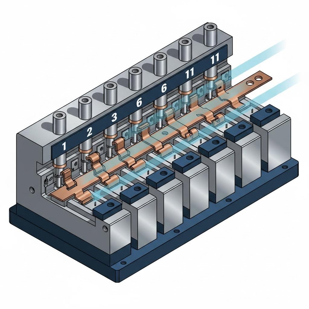
In a progressive die setup, coil stock feeds through multiple stations within a single die set. Each press stroke advances the strip one "progression," with different operations occurring simultaneously at each station. The workpiece remains attached to the carrier strip until the final cutoff station.
- Feeding system: Servo-driven roll feeds or air feeds advance material with ±0.025 mm accuracy
- Strip layout: Engineers optimize material utilization by nesting parts and minimizing scrap between progressions
- Advantages: High-speed production (300+ SPM possible), minimal part handling, consistent positioning between operations
- Best for: High-volume parts with multiple features that can be formed in sequence
Single-Station (Transfer Die) Stamping:
Transfer operations use separate die stations with mechanical transfer mechanisms moving parts between stations. Parts are cut from the strip early and handled individually through subsequent forming operations.
- Transfer system: Mechanical fingers, walking beams, or robotic arms move parts at precisely timed intervals
- Advantages: Accommodates larger parts, deeper draws, and more complex forming sequences than progressive dies allow
- Best for: Larger components, deep-drawn parts, or geometries requiring more forming clearance than progressive strip layouts permit
The choice between progressive and transfer stamping often determines project economics. Progressive dies require higher tooling investment but deliver lower per-piece costs at volume. Transfer tooling costs less initially but runs slower—making it ideal for moderate volumes or parts too large for progressive strip feeding.
With the complete workflow mapped out, the next critical decision involves selecting the right material for your specific application—a choice that affects formability, cost, and final part performance.
Material Selection Guide for Stamping Success
Ever wonder why some stamped parts crack while others form flawlessly? The answer often lies in metal stamping materials selection. Different metals behave dramatically differently under forming pressure—what works perfectly for a shallow bracket might fail catastrophically in a deep-drawn enclosure. Understanding these material behaviors transforms guesswork into confident engineering decisions.
According to precision stamping experts, designers, engineers, and stampers must work together to balance design intent with manufacturability. The right metal for stamping depends on mechanical properties, chemical characteristics, and how the material will perform both during forming and in the finished application.
Steel Grades and Their Stamping Characteristics
Steel remains the workhorse of precision metal stamping materials, offering an exceptional range of strength, formability, and cost options. However, not all steels stamp equally well.
Carbon Steel
Low-carbon steels (typically 0.05-0.25% carbon) deliver excellent formability with good weldability. These materials bend easily, resist cracking during deep drawing, and accept a wide range of surface finishes. The tradeoff? They require corrosion protection for most applications.
- Typical thickness range: 0.3 mm to 6 mm
- Formability: Excellent—ideal for complex bends and draws
- Key consideration: Lower carbon content means easier forming but reduced hardness
Stainless Steel Stamping
When corrosion resistance matters, stainless steel metal stamping becomes essential. The chromium content (minimum 10.5%) creates a protective oxide layer that resists rust and chemical attack. However, stainless steel stamping demands more tonnage and careful tooling design.
According to material selection guides, 304 stainless steel offers tensile strength of ≥515 MPa with salt spray resistance of ≥48 hours—making it ideal for medical equipment shells and charging pile terminals. For applications without rust prevention requirements, 430 stainless provides similar forming characteristics at lower cost.
- Typical thickness range: 0.3 mm to 4 mm for standard stamping
- Formability: Good, but requires 50-100% more forming force than carbon steel
- Key consideration: Higher work hardening rate means progressive operations must account for increasing material strength
High-Strength Steel
Automotive and structural applications increasingly demand high-strength low-alloy (HSLA) steels. These materials offer superior strength-to-weight ratios but present significant springback challenges.
- Typical thickness range: 0.5 mm to 3 mm
- Formability: Moderate—tighter bend radii and more aggressive springback compensation required
- Key consideration: Die design must account for elastic recovery up to 2-3 times that of mild steel
Lightweight Metals - Aluminum and Its Challenges
The aluminum stamping process delivers weight savings of approximately 65% compared to steel—a critical advantage for automotive, aerospace, and portable electronics applications. But stamped aluminum presents unique challenges that catch unprepared manufacturers off guard.
Why Aluminum Behaves Differently
Aluminum's lower modulus of elasticity (roughly one-third that of steel) creates pronounced springback during forming. The material also work-hardens rapidly, meaning each forming operation increases hardness and reduces ductility for subsequent operations.
Common Aluminum Alloys for Stamping
- 5052/5083: Non-heat-treatable alloys with excellent corrosion resistance and good formability. Ideal for marine applications and general-purpose stamping.
- 6061-T6: Heat-treatable alloy offering good mechanical properties and weldability. Per industry case studies, 6061-T6 enabled a 5G base station heat sink design meeting weight targets while increasing heat dissipation efficiency by 25%.
- 7075: High-strength alloy with excellent fatigue resistance—commonly used in aerospace applications where strength-to-weight ratio is paramount.
Stamping Considerations for Aluminum
- Typical thickness range: 0.3 mm to 4 mm
- Formability: Good to excellent depending on alloy and temper
- Key consideration: Galling (material transfer to tooling) requires specialized lubricants and sometimes surface-treated dies
Copper and Brass for Electrical Applications
When electrical conductivity drives material selection, copper and its alloys become essential. These materials dominate electronic connectors, battery contacts, and EMI shielding applications.
Pure Copper
With conductivity reaching 98% IACS (International Annealed Copper Standard), pure copper delivers unmatched electrical performance. It punches easily into micro-contacts and forms well in moderate-depth draws.
- Typical thickness range: 0.1 mm to 2 mm
- Formability: Excellent ductility enables complex shapes
- Key consideration: Higher cost than brass alternatives; work hardening requires annealing between aggressive forming operations
Brass (Copper-Zinc Alloys)
Brass offers an attractive balance of conductivity, formability, and cost. H62 brass delivers hardness of HB≥80 with excellent machinability—often eliminating secondary processing after stamping.
- Typical thickness range: 0.2 mm to 3 mm
- Formability: Excellent—particularly well-suited for progressive die stamping
- Key consideration: Lower conductivity than pure copper (approximately 28% IACS for common alloys) but significantly lower material cost
Material Properties That Affect Stampability
Beyond selecting a material family, understanding specific properties helps predict forming behavior:
- Ductility: Measures how much a material can stretch before fracturing. Higher ductility enables deeper draws and tighter bends without cracking.
- Yield Strength: The stress level at which permanent deformation begins. Lower yield strength means easier forming but potentially less structural rigidity in finished parts.
- Work Hardening Rate: How quickly material strength increases during deformation. High work hardening rates require more forming force in progressive operations and may necessitate intermediate annealing.
- Springback Tendency: The elastic recovery after forming force is removed. Materials with higher modulus of elasticity exhibit less springback—a critical factor for maintaining dimensional accuracy.
Material Comparison for Stamping Applications
| Material | Tensile Strength (MPa) | Density (g/cm³) | Formability | Typical Applications | Relative Cost |
|---|---|---|---|---|---|
| Low-Carbon Steel | 270-410 | 7.85 | Excellent | Brackets, enclosures, structural parts | Low |
| 304 Stainless Steel | ≥515 | 7.9 | Good | Medical equipment, food processing, automotive | Medium-High |
| Galvanized Steel | ≥375 | 7.8 | Good | Appliance panels, chassis brackets | Low-Medium |
| Aluminum (6061) | 110-310 | 2.7 | Good | Heat sinks, electronics housings, automotive | Medium |
| Copper | 200-450 | 8.9 | Excellent | Electrical contacts, EMI shields, connectors | High |
| Brass (H62) | 300-600 | 8.5 | Excellent | Lock components, terminals, decorative parts | Medium |
Making the Right Material Decision
Selecting precision metal stamping materials requires balancing three factors:
- Process Compatibility: Match material ductility to your forming requirements. Progressive die stamping favors materials like brass that maintain formability through multiple operations. Deep drawing applications benefit from low yield-strength-ratio materials like 304 stainless.
- Application Requirements: Let end-use drive your decision. Electronics and 5G applications demand conductivity plus lightweight properties—pointing toward aluminum or copper. Outdoor and medical applications require corrosion resistance, making stainless steel the logical choice.
- Cost Optimization: Consider material substitution for high-volume production. Using brass instead of pure copper for lock cylinder components can reduce material costs by 20% or more while maintaining acceptable performance.
With the right material selected, the next challenge becomes designing tooling that forms it correctly—a topic where die design fundamentals and modern simulation technology combine to prevent costly trial-and-error approaches.
Tooling and Die Design Fundamentals
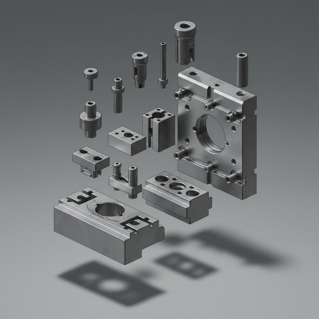
You've selected the perfect material for your application—but here's the reality check: even the best material will fail if your metal stamping dies aren't designed and built correctly. Tooling represents the heart of any stamping operation, directly determining part quality, production speed, and ultimately, project economics. Yet many manufacturers treat die design as an afterthought, leading to costly trial-and-error cycles that delay production and drain budgets.
Let's explore what separates successful die programs from frustrating failures—starting with the materials that make precision die & stamping possible.
Die Materials and Construction Principles
What makes one die last 50,000 cycles while another fails after 5,000? The answer begins with material selection. According to AHSS Insights research, tool and die wear occurs due to friction between sheet metal and tooling surfaces. Damage to the die surface causes gradual material loss, scoring, and burnishing—all of which can become stress risers leading to premature part failure.
Common Die Material Categories:
- Cast Iron: Gray cast irons (G2500, G25HP, G3500) and pearlitic ductile irons (D4512, D6510, D7003) offer cost-effective solutions for lower-strength materials and moderate volumes
- Cast Steel: Grades like S0030, S0050A, and S7140 provide improved toughness over cast iron for more demanding applications
- Tool Steels: TD2 (high wear/low shock resistance), TS7 (high shock/low wear resistance), and TA2 (balanced medium wear/medium shock resistance) address specific application requirements
- Powder Metallurgy (PM) Tool Steels: These advanced materials offer superior combinations of wear resistance and toughness impossible to achieve with conventional tool steels
Here's what many overlook: when stamping advanced high-strength steels (AHSS), the sheet metal hardness can approach the tooling hardness itself. Some martensitic grades reach Rockwell C values exceeding 57—meaning your die stamping machine tooling faces a formidable opponent with every stroke.
Surface Treatments That Extend Die Life:
Raw tool steel rarely delivers optimal performance. Surface treatments dramatically improve wear resistance and reduce friction:
- Flame or Induction Hardening: Creates hardened surface layers, though carbon content limits achievable hardness
- Nitriding: Gas nitriding or plasma (ion) nitriding creates hard, wear-resistant surfaces. Ion nitriding is faster and minimizes the brittle "white layer"
- PVD Coatings: Titanium nitride (TiN), titanium aluminum nitride (TiAlN), and chromium nitride (CrN) coatings reduce galling and extend tool life
- CVD and TD Coatings: Provide stronger metallurgical bonds but require processing at approximately 1000°C, potentially softening the die and requiring rehardening
The results speak for themselves: studies show that ion nitrided tool steel with chromium nitride PVD coating produced more than 1.2 million parts, while chrome-plated tooling failed after just 50,000 parts stamping the same material.
Progressive Dies vs Transfer Dies
Choosing between progressive and transfer die configurations fundamentally shapes your production economics and part capabilities. Each approach offers distinct advantages that match different application requirements.
Progressive Die Characteristics:
In progressive operations, the strip advances through multiple stations within a single die set. Each press stroke performs different operations at each station simultaneously, with the workpiece remaining attached to a carrier strip until final cutoff.
- Higher tooling complexity: Progressive dies require sheet guides, lifters, and precise station alignment
- Faster production speeds: Parts are produced much faster because semi-finished material advances autonomously
- Best for high volumes: The higher tooling investment amortizes over large production runs
- Ideal for smaller parts: Generally better suited for producing sets of smaller components
Transfer Die Characteristics:
Transfer stamping uses independent die stations with mechanical arms moving parts between operations. The base material can be eliminated early in the process, and each phase operates independently.
- Simpler individual die design: Each station requires less complexity than progressive die stations
- More cost-effective for lower volumes: Lower tooling investment makes economic sense for smaller batches
- Better for larger parts: Transfer dies are generally considered more suitable for producing large components
- Flexibility in material handling: Parts can be rotated, flipped, or repositioned between stations
The decision between progressive and transfer tooling often determines whether a project achieves its cost targets. Progressive dies demand higher upfront investment but deliver lower per-piece costs at volume—sometimes 40-60% lower than transfer alternatives for suitable part geometries.
Critical Die Design Principles
Beyond material and configuration selection, specific design parameters determine whether your automotive stamping die produces good parts or generates endless quality issues.
Key Design Considerations:
- Punch-to-Die Clearance: Higher-strength materials require increased clearances compared to mild steel. This clearance acts as leverage to bend and break the slug—stronger materials need longer "levers"
- Bend Radii: Minimum inside bend radius typically equals material thickness for mild steel; high-strength steels may require 2x thickness or more
- Draw Ratios: Maximum blank-to-punch diameter ratios of 1.8-2.0 for single operations; deeper draws require multiple stages
- Strip Layout Optimization: Material utilization targets of 75-85% for progressive dies; poor layouts waste material and increase per-part costs
Common Design Pitfalls to Avoid:
- Insufficient clearance: Tight cutting clearances increase galling and chipping tendency, especially with AHSS
- Sharp corners in die cavities: Create stress concentrations leading to cracking and premature failure
- Inadequate venting: Trapped air causes inconsistent forming and potential material damage
- Ignoring springback compensation: Failure to account for elastic recovery results in out-of-tolerance parts
- Underestimating tonnage requirements: AHSS grades can require four times the working loads of mild steel
CAE Simulation: Predicting Defects Before Cutting Steel
Modern metal stamping die design increasingly relies on Computer-Aided Engineering (CAE) simulation to validate designs before physical tooling production. According to sheet metal forming simulation experts, virtual die try-outs address several critical challenges: material selection and springback prediction, part and process design optimization, and process parameter fine-tuning.
Why does this matter? Defects often emerge only during the first physical trials—when corrections are time-consuming and costly. Simulation catches problems like wrinkling, cracking, and excessive thinning while changes are still just CAD modifications rather than expensive die rework.
What CAE Simulation Reveals:
- Material flow patterns during forming
- Potential thinning or thickening zones
- Springback magnitude and compensation requirements
- Blank holder force optimization
- Draw bead placement for material flow control
Advanced die design capabilities combined with simulation technology dramatically reduce development time and improve first-pass success rates. Suppliers leveraging these technologies—such as those offering comprehensive mold design and fabrication capabilities with IATF 16949 certification—can achieve rapid prototyping in as little as 5 days with first-pass approval rates exceeding 90%.
Maximizing Tool Life Through Proper Maintenance
Even perfectly designed steel stamping dies require ongoing maintenance to sustain performance. Research indicates that die wear beyond a critical point necessitates replacement—impacting turnaround times and causing production losses.
Five Primary Die Failure Modes:
- Wear: Gradual material loss from abrasive or adhesive contact—countered by high-hardness tool steels and coatings
- Plastic Deformation: Occurs when contact stress exceeds the die's compressive yield strength—requires adequate hardness
- Chipping: Fatigue-related edge damage from cyclic stress—addressed through toughness-optimized tool steels
- Cracking: Catastrophic failure when stress exceeds fracture toughness—prevented by eliminating stress concentrators and proper heat treatment
- Galling: Material transfer between sheet and die surfaces—controlled through coatings and lubrication
Maintenance Best Practices:
- Proper tempering: Dies placed in service without correct tempering will experience early failure. High-alloy tool steels (D, M, or T grades) require multiple tempering steps
- Regular inspection intervals: Scheduled inspection before wear progresses to part quality impact
- Coating reapplication: PVD coatings may require periodic renewal after extended production
- Insert replacement strategy: Using replaceable inserts in high-wear locations minimizes complete die replacement costs
Consider this case study: A manufacturer stamping FB 600 steel experienced D2 tool failure after just 5,000-7,000 cycles—compared to the 50,000 cycles typical with conventional steels. Switching to a powder metallurgy tool steel with optimized impact resistance restored die life to 40,000-50,000 cycles—a 10x improvement through proper material selection.
With proper die design and maintenance practices established, the next critical skill becomes recognizing and correcting the defects that inevitably arise during production—knowledge that separates troubleshooting experts from those stuck in endless quality battles.
Troubleshooting Common Stamping Defects
You've designed the perfect die, selected the ideal material, and set up your press with precision—yet defective stamped parts still show up on the inspection table. Sound familiar? Even well-optimized operations encounter quality issues that can halt production and frustrate quality teams. The difference between struggling manufacturers and efficient ones? Knowing exactly what causes each defect and how to fix it fast.
According to industry analysis, quality problems in stamped metal parts not only affect appearance but also reduce corrosion resistance and product lifespan. Let's decode the most common defects and the proven solutions that get production back on track.
Diagnosing Wrinkling and Cracking Issues
These two defects represent opposite ends of the material flow spectrum—yet both can ruin stamped metal components in seconds. Understanding their root causes reveals surprisingly straightforward solutions.
Wrinkling
When metal stamped parts develop irregular corrugations or waves on their surfaces, you're seeing the result of compressive stress exceeding the material's ability to maintain form. This typically occurs in thin sheets or curved areas where material flows faster than the die cavity can control it.
Common causes include:
- Insufficient blank holder force allowing excess material movement
- Draw ratios exceeding material capabilities (depth/diameter ratios greater than 2.5)
- Improper draw bead design failing to control material flow
- Material thickness too thin for the forming geometry
Proven solutions:
- Increase blank holder force—but carefully, as excessive force causes cracking
- Add or optimize draw beads to balance material flow
- Consider step-by-step drawing (60% initial draw, followed by secondary shaping)
- Use servo hydraulic pad systems for multi-point blank holding force control
Cracking
Cracks appear when tensile stress exceeds the material's ductility limits—typically at corners, deep draw walls, or areas of high strain concentration. According to metal stamping defect analysis, cracking represents a deformation failure that may cause part damage and serious quality problems.
Common causes include:
- Excessive strain beyond material elongation limits
- Too small die corner radius (R should be ≥4t, where t is material thickness)
- Blank holder force too high, restricting material flow
- Poor material ductility or incorrect material selection
Proven solutions:
- Increase die corner radii to reduce stress concentration
- Add intermediate annealing processes for deep cylinder parts
- Use hot forming (200-400°C) for high-strength steel applications
- Select materials with better elongation properties (such as SPCE instead of SPCC)
Controlling Springback in Formed Parts
Springback frustrates manufacturers of stamped steel parts more than almost any other defect. When forming pressure releases, stored elastic energy causes the material to partially return toward its original shape—leaving you with parts that don't match specifications.
According to springback prevention research, this problem intensifies dramatically with high-strength steels. The higher yield strength of AHSS means greater elastic energy storage during forming—and correspondingly more aggressive springback upon tool release.
Why some materials spring back more:
- Higher yield strength-to-modulus ratio stores more elastic energy
- Thinner materials exhibit more pronounced springback than thicker gauges
- Complex bend geometries create unpredictable recovery patterns
Effective springback compensation methods:
- Overbending: Intentionally bend to a more acute angle, expecting spring-back to the target dimension
- Coining/Staking: Apply extremely high compressive pressure at bend radii to reduce internal stresses
- Die compensation: Use CAE simulation to predict springback and modify die geometry so parts spring back into correct shape
- Hot stamping: Form at elevated temperatures (over 900°C for press hardening) to virtually eliminate springback
- Process optimization: Adjust blank holder force and dwell time to allow stress relaxation
Eliminating Burrs and Surface Imperfections
Burrs exceeding tolerance (typically >0.1mm) and surface defects like scratches or indentations create assembly problems, safety hazards, and customer rejections. These precision stamping parts issues often trace back to tooling condition or process parameters.
Burr Formation
Burrs form when cutting edges fail to cleanly shear material, leaving attached material on part edges. Per stamping quality guides, the cutting edge gap and tool sharpness directly determine burr severity.
Solutions include:
- Adjust clearance to 8-12% of material thickness (use lower values for mild steel)
- Grind dies regularly—inspect every 50,000 strokes
- Consider fine blanking technology using V-shaped blank holders with anti-thrust force
- For copper terminals: switch to zero-gap blanking methods
Surface Defects
Scratches, indentations, and orange peel patterns on stamped sheet metal typically originate from tooling surface conditions or contamination between die surfaces.
Solutions include:
- Polish die surfaces to Ra 0.2μm or less; apply chrome plating or TD treatment
- Use volatile stamping oils (ester-based lubricants)
- Pre-clean materials to remove dust, oil, and oxides
- For aluminum parts: replace metal pressure plates with nylon alternatives
Quick Troubleshooting Reference
When production issues arise, quick diagnosis saves hours of trial-and-error. This reference table covers the most common stamped parts defects with their causes and corrective actions:
| Defect Type | Common Causes | Corrective Actions |
|---|---|---|
| Wrinkling | Low blank holder force; excessive draw ratio; poor material flow control | Increase blank holder force; add draw beads; use step-by-step drawing |
| Cracking | Excessive strain; small die radii; high blank holder force; low material ductility | Increase die corner radius (R≥4t); add annealing; use hot forming for HSS |
| Springback | High yield strength material; elastic energy release; inadequate forming force | Overbend compensation; coining; CAE-driven die modification; hot stamping |
| Burrs | Worn cutting edge; improper punch-die clearance; tool chipping | Adjust clearance to 8-12% of thickness; grind dies every 50K strokes; fine blanking |
| Dimensional Errors | Die wear; material springback; press parallelism issues; positioning errors | Add guide posts; use springback compensation design; check press calibration |
| Surface Scratches | Rough die surfaces; contamination; inadequate lubrication | Polish dies to Ra≤0.2μm; clean materials; use volatile stamping oils |
| Uneven Thinning | Blocked material flow; small die radius; poor lubrication | Optimize draw rib layout; locally apply high-viscosity lubricant; use ductile materials |
| Warping/Distortion | Uneven stress release; improper clamping force distribution; accumulated stress | Add shaping process; optimize layout along rolling direction; pre-bending structure |
Prevention Beats Correction Every Time
Rather than constantly fighting defects, proactive manufacturers build prevention into their processes:
- Design stage: Use CAE software to simulate material flow, springback, and stress distribution before cutting steel. Avoid sharp corners—R angles should be at least 3x material thickness
- Process control: Develop standard operating procedures specifying blank holder force, speed, and other critical parameters. Conduct first-piece full-size inspection using 3D scanners
- Tooling maintenance: Establish die life records and regularly replace wearing components. Apply coatings like TiAlN to improve wear resistance
- Material management: Inspect incoming material properties (tensile testing, thickness tolerance ±0.02mm) and store different batches separately
Understanding these defect patterns and solutions transforms reactive firefighting into proactive quality management. But knowing what causes problems is only part of the equation—understanding how these quality issues impact project costs helps justify the investment in prevention.
Cost Factors in Metal Stamping Projects
You've mastered defect prevention and quality control—but here's the question that keeps procurement professionals awake at night: how do you accurately predict what a stamping project will actually cost? The gap between initial quotes and final invoices often catches manufacturers off guard, especially when hidden cost drivers emerge mid-production.
Here's the reality: according to industry cost analysis, you might receive quotes ranging from $0.50 to $5.00 per piece for seemingly identical stamped parts—and both suppliers could be right. The difference lies in understanding what truly drives stamping economics.
Understanding Tooling Investment and ROI
Here's the bombshell that surprises most buyers: tooling is the first influence on the price of production metal stamping—not material, not labor. Each custom die represents a precision-engineered masterpiece built specifically for your part geometry.
What drives tooling costs?
- Simple blanking dies: $5,000-$15,000 for basic cutting operations
- Moderate complexity dies: $15,000-$50,000 for parts with multiple bends and features
- Progressive dies: $50,000-$150,000+ for high-volume parts requiring multiple stations
- Complex automotive stamping dies: $100,000-$500,000 depending on part complexity and production requirements
But here's what catches manufacturers off guard: design changes after tooling completion can add $5,000-$15,000 for minor adjustments—or 30-50% of the original investment for major rework. According to automotive stamping specialists, this reality makes thorough design validation and prototyping essential before committing to production dies.
The key insight? Tooling is a fixed cost that gets divided among all your parts. Make 1,000 parts, and that expensive die hits each part hard. Make 100,000 parts, and the tooling investment becomes almost invisible in your per-piece calculation.
How Volume Affects Per-Part Economics
When does a metal stamping machine become your cost-saving hero versus an expensive mistake? The answer lies in understanding the volume threshold where stamping economics turn favorable.
Consider this comparison from production data:
- Sheet metal fabricated parts costing $15 each can drop to $3-12 through stamping
- Projects have demonstrated 80% cost reductions with lead times shrinking from 10 weeks to 4 weeks
- Break-even typically occurs within 12-24 months depending on annual volume
The magic threshold? Industry analysis suggests stamping becomes economical at approximately 10,000+ parts per month—when your stamping plant can set up once and let the press run efficiently. Below that range, laser cutting or CNC machining might serve you better. Above it, you're in stamping's sweet spot where the economics truly shine.
| Annual Volume | Typical Payback Period | Per-Part Cost Reduction | Recommended Approach |
|---|---|---|---|
| Under 10,000 | May not achieve payback | Limited savings | Consider fabrication alternatives |
| 10,000-50,000 | 18-24 months | 30-50% | Evaluate based on part complexity |
| 50,000-100,000 | 12-18 months | 50-70% | Strong stamping candidate |
| 100,000+ | 6-12 months | 70-80%+ | Ideal for progressive die investment |
Hidden Costs That Impact Project Budgets
Beyond tooling and volume, several factors quietly inflate project costs—often catching manufacturers unprepared.
Material Costs and Scrap Rates
The cost formula isn't just about raw material price. According to stamping cost experts: Total production cost = N×(Raw material cost) + N×(Hourly Cost)×(Cycle time per piece)/(Efficiency) + Tooling costs.
What this means practically:
- Material utilization matters: Smart progressive die design nests parts like a puzzle, targeting 75-85% material utilization. Poor layouts waste money in the scrap bin
- Steel price volatility: Prices can swing 20-30% based on global conditions—build 10-15% buffer into budgets
- Material selection: Carbon steel remains overwhelmingly the most cost-effective for large-volume stamping; stainless and aluminum carry premiums
Secondary Operations
Many projects underestimate costs beyond the press:
- Deburring, tumbling, or polishing
- Heat treatment or surface finishing
- Tapping, welding, or assembly operations
- Inspection and documentation requirements
Here's the smart play: precision in metal stamping often reduces the need for additional post-processing. Sometimes investing in better tooling upfront actually saves money by eliminating downstream operations.
Tolerance Requirements
Every time you tighten tolerances beyond standard ±0.005" to ±0.010", you're asking for more complex stamping machinery, slower production speeds, or additional secondary operations. According to experienced tool designers, what used to be ±0.005" is now often specified as ±0.002" or even ±0.001"—each step dramatically increasing manufacturing complexity and cost.
Cost Reduction Strategies That Work
Want to optimize your metal stamping equipment investment? Apply these design-for-manufacturability principles:
- Simplify geometry: Complex curves and sharp internal corners inflate tooling costs. Simple part geometries with straight cuts and basic bends are cost-effective champions
- Optimize bend radii: Make bend radius at least equal to material thickness—larger radii improve formability while reducing tooling wear
- Reduce feature count: Each additional hole, slot, or embossed detail adds die complexity and maintenance cost
- Consider material substitution: Can you use steel instead of stainless? Standard gauge instead of custom thickness?
- Increase order volumes: Blanket orders with scheduled releases optimize both your costs and supplier planning
- Engage suppliers early: Manufacturers often have insights into cost reduction opportunities not obvious from design drawings
When to Choose Stamping Over Alternatives
Use this decision framework to determine if stamping makes financial sense for your project:
- Choose stamping when: Annual volumes exceed 50,000 parts, parts require multiple forming operations, geometry starts as flat sheet, and you can commit to stable designs
- Consider alternatives when: Volumes are under 10,000 annually, designs change frequently, parts require extensive machined features, or deep internal cavities exceed material formability limits
Metal stamping can reduce part costs by 20% to 80% versus other sheet metal manufacturing processes—but only when the economics align with your production requirements.
Understanding these cost dynamics transforms stamping from a mysterious expense into a strategic manufacturing decision. But achieving those cost savings requires maintaining consistent quality throughout production—which brings us to the quality control and inspection standards that protect both your investment and your reputation.
Quality Control and Inspection Standards
You've optimized costs, designed robust tooling, and selected the perfect material—but how do you prove every stamped part meets specifications? In precision stamping operations, quality control isn't optional; it's the difference between successful OEM partnerships and costly recalls. According to industry experts, quality assurance in metal stamping ensures high precision and reliability, especially for industries demanding exact specifications like automotive, aerospace, and medical sectors.
Let's explore the quality systems that separate world-class manufacturers from those constantly fighting customer complaints.
In-Process Quality Monitoring Systems
Waiting until parts reach final inspection to discover problems? That's the most expensive approach imaginable. Modern precision metal stamping operations embed quality verification throughout production—catching issues in seconds rather than after thousands of defective parts stack up.
Real-Time Monitoring Technologies:
- Tonnage signature analysis: Monitors press force throughout each stroke, detecting variations indicating tool wear, material inconsistencies, or feeding problems
- In-die sensors: Detect misfeeds, double blanks, and slug retention before they cause die damage or part defects
- Statistical Process Control (SPC): According to quality assurance specialists, SPC involves collecting and analyzing data to predict trends and ensure processes stay within predefined limits
- Optical vision systems: Camera-based inspection verifies part presence, orientation, and critical features at production speed
Why does in-process monitoring matter so much? Consider this: a single defect in an aerospace component can trigger recalls costing millions. By catching anomalies immediately, manufacturers prevent defective parts from receiving costly downstream processing—or worse, reaching customers.
Dimensional Verification Methods
How do you confirm that metal stamping components actually match their specifications? The answer depends on your precision requirements, production volumes, and part complexity.
Coordinate Measuring Machines (CMM)
CMM inspection represents the gold standard for metal precision stamping verification. According to precision stamping quality guides, these sophisticated instruments capture three-dimensional measurements with accuracies reaching micrometers, providing comprehensive geometric analysis including flatness, perpendicularity, concentricity, and profile deviations.
The measurement process begins with proper workpiece fixturing, followed by systematic probing of critical features according to predetermined inspection plans. Temperature compensation algorithms account for thermal expansion effects, ensuring measurement reliability across varying environmental conditions.
Go/No-Go Gauging
For high precision metal stamping operations where CMM testing would create bottlenecks, dedicated go/no-go gauges provide rapid production-floor verification. These fixtures incorporate critical dimensional limits as physical constraints, allowing operators to verify part conformance without specialized measurement training.
Additional Verification Technologies:
- Laser scanning: Creates accurate 3D models by capturing detailed information about shape and position
- Optical comparators: Project magnified part profiles for visual comparison against toleranced overlays
- Surface profilometers: Measure Ra, Rz, and other roughness parameters for surfaces requiring precise finish specifications
- Hardness testing: Rockwell, Brinell, and Vickers methods verify material properties affecting part performance
Essential Quality Checkpoints
Effective automotive stamping quality systems establish verification points throughout the entire manufacturing workflow:
- Incoming material inspection: Verify thickness tolerance (typically ±0.02mm), surface condition, and mechanical properties through tensile testing
- First-piece approval: Full dimensional verification before production release, comparing actual measurements against CAD specifications
- In-process sampling: SPC-based sampling at defined intervals—frequency determined by process capability data
- Tool condition monitoring: Regular inspection of cutting edges and forming surfaces, with grinding intervals based on stroke counts
- Post-operation verification: Inspection between secondary operations prevents defective parts from receiving costly downstream processing
- Final inspection: 100% inspection for critical features or statistical sampling for stable, high-capability processes
- Documentation review: Certificates of conformance and traceability records before shipment
Meeting Industry Certification Standards
When supplying automotive metal stamping components to major OEMs, certification requirements aren't suggestions—they're mandatory gates that determine supplier eligibility.
ISO 9001: The Foundation
ISO 9001 certification provides a framework ensuring products meet global quality requirements. According to quality management experts, this certification requires rigorous documentation and auditing, ensuring every part of the process is accounted for. As the saying goes, "If it's not documented, it's not done."
IATF 16949: The Automotive Standard
For automotive stamping applications, IATF 16949 certification elevates quality requirements significantly. Originally drafted by the International Automotive Task Force, this standard harmonizes certification programs across the global automotive industry. According to IATF-certified manufacturers, the certification focuses on three primary aims:
- Improve both product quality and consistency along with the manufacturing processes behind them
- Establish "supplier of choice" status among leading automotive manufacturers through proven accountability
- Integrate seamlessly with ISO certification standards for comprehensive quality management
Much of the IATF 16949 literature focuses on defect prevention and production variance minimization—aligning perfectly with lean manufacturing principles that reduce scrap and waste.
What Certification Means for Your Projects
Working with certified suppliers reduces risk in high-precision applications. Suppliers demonstrating IATF 16949 certification with proven quality metrics—such as those achieving 93% first-pass approval rates—provide confidence that parts will meet stringent OEM requirements without costly iterations.
Quality assurance in metal stamping is about more than meeting standards—it's about exceeding them, ensuring that every stamped piece is a testament to precision and reliability.
The investment in robust quality systems pays dividends beyond customer satisfaction. By preventing defects rather than detecting them after the fact, manufacturers reduce scrap, minimize rework, and maintain the production efficiency that keeps stamping economics favorable. That comprehensive approach—from in-process monitoring through final certification—is what positions precision stamping suppliers as trusted partners rather than commodity vendors.
Frequently Asked Questions About Metal Stamping Manufacturing
1. What are the 7 steps in the stamping method?
The metal stamping workflow follows seven sequential stages: design and engineering (CAD/CAM modeling and process simulation), tool and die creation (CNC machining and heat treatment), material selection and preparation (inspection, slitting, leveling, lubrication), press setup and validation (shut height adjustment, stroke programming, tonnage settings), stamping execution (production with real-time monitoring and SPC), secondary operations (deburring, heat treatment, surface finishing), and quality inspection with shipping (CMM verification, documentation, PPAP for automotive). Each stage includes specific quality checkpoints to ensure parts meet specifications before advancing.
2. What are the four types of metal stamping?
The four primary metal stamping types are progressive die stamping (multiple operations in a single die with strip advancement), transfer die stamping (independent stations with mechanical part transfer), deep draw stamping (creating cup or box shapes with significant depth), and micro/miniature stamping (precision components for electronics and medical devices). Progressive stamping suits high-volume smaller parts, while transfer stamping accommodates larger components. Deep drawing handles cylindrical geometries, and micro stamping achieves tolerances as tight as ±0.001 inches for miniature applications.
3. What is the stamping process?
Metal stamping is a cold-forming manufacturing process that transforms flat sheet metal into precisely shaped components using controlled force application. Dies and presses work together to cut, bend, and form metal without melting it—distinguishing stamping from casting or machining. The process includes nine core operations: blanking, punching, coining, bending, flanging, stretching, embossing, curling, and grooving. Each operation addresses specific forming requirements, with tolerances ranging from ±0.01mm for coining to ±1° for bending operations.
4. How do you choose the right press type for metal stamping?
Press selection depends on production speed, force requirements, and part geometry. Mechanical presses deliver the highest speeds (up to 1,400+ SPM) for high-volume flat parts but achieve full tonnage only near bottom dead center. Hydraulic presses provide full force at any stroke position, making them ideal for deep drawing and complex forms requiring dwell time. Servo presses combine mechanical speed with hydraulic flexibility through programmable stroke profiles—though at higher initial investment. Consider your part's depth, material strength, production volume, and tolerance requirements when selecting press technology.
5. What materials work best for metal stamping applications?
Material selection depends on formability, strength requirements, and end-use conditions. Low-carbon steel offers excellent formability at low cost for brackets and enclosures. Stainless steel (304, 430) provides corrosion resistance for medical and food applications but requires 50-100% more forming force. Aluminum alloys (5052, 6061, 7075) deliver weight savings of 65% versus steel but exhibit pronounced springback. Copper and brass excel in electrical applications due to high conductivity. IATF 16949-certified suppliers like Shaoyi can help optimize material selection for your specific requirements.