 Small batches, high standards. Our rapid prototyping service makes validation faster and easier —

What Your Metal Bending Company Won't Tell You
Understanding What a Metal Bending Company Does
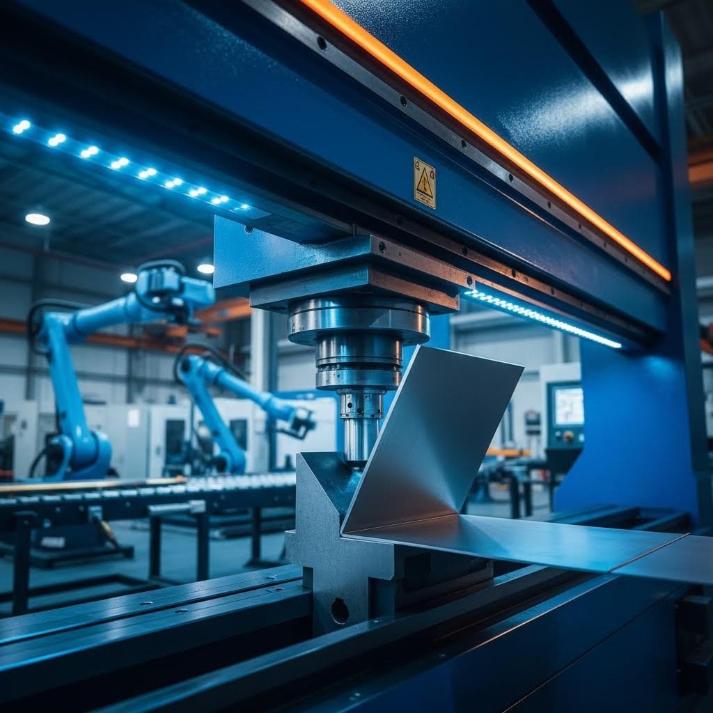
Ever wondered how a flat sheet of steel transforms into a precisely angled bracket or a complex automotive component? That's exactly what a metal bending company specializes in. These specialized manufacturers use controlled force to reshape metal sheets, bars, and tubes into specific angles, curves, or intricate profiles without cutting or welding the material.
At its core, metal bending is a manufacturing process that plastically deforms metal along a straight line. The workpiece is placed on a die, and a punch applies force to create the bend at the desired location. This seemingly simple principle enables the creation of sturdy one-piece structures like brackets, enclosures, and frames from flat blanks.
What Metal Bending Companies Actually Do
Professional metal benders handle far more than basic bends. They manage everything from calculating precise force requirements and bend sequences to selecting the right tooling for each unique project. A typical operation involves:
- Design and planning: Engineers create flat patterns and specify bend lines, angles, and radii while applying bend allowances
- Blank preparation: Cutting sheet metal to shape using laser cutting, punching, or stamping
- Machine setup: Selecting proper punch and die combinations for the specific material and bend requirements
- Precision bending: Executing single or multiple bends with computer-controlled accuracy
- Quality verification: Checking finished parts against specifications and applying finishing processes
These professionals work with materials ranging from mild steel and stainless steel to aluminum, copper, and brass. Whether you need custom metal bending for a prototype or high-volume production runs, these facilities leverage equipment capable of exerting forces exceeding 100 tons to bend steel upward of 3mm thick.
The Role of Professional Bending Services in Manufacturing
What separates professional metal bending services from DIY attempts? Precision, repeatability, and expertise. While you might bend a simple piece of aluminum in your garage, professional-grade bending involves understanding material springback, calculating K-factors, and compensating for the elastic recovery that occurs after the bending force is removed.
Professional steel bending and fabrication services deliver tolerances of ±0.5° or ±1° in bend angles consistently across thousands of parts. They understand that bending induces both tensile and compressive stresses in metal, and they know exactly how much to over-bend each material to achieve the correct final angle.
These bending services support virtually every manufacturing sector you can imagine:
- Automotive: Chassis components, brackets, and structural supports
- Aerospace: Precision parts requiring strict tolerances and certifications
- Construction: Structural components, architectural panels, and building hardware
- Electronics: Enclosures, chassis, and mounting brackets for equipment
- Industrial equipment: Machine guards, housings, and support structures
Throughout this guide, you'll discover the techniques, terminology, and insider knowledge that most providers assume you already understand. From air bending versus bottom bending to preventing common defects, you're about to gain the expertise needed to communicate effectively with any metal bending partner and make informed decisions for your next project.
Metal Bending Techniques Every Buyer Should Know
Sounds complex? Here's the thing most providers won't explain: not all bending techniques are created equal. The method used to form your part directly impacts its precision, surface finish, and structural integrity. Understanding these differences empowers you to ask the right questions and select the optimal approach for your project. Let's break down the six primary sheet metal bending techniques that drive modern manufacturing.
Air Bending Versus Bottom Bending Explained
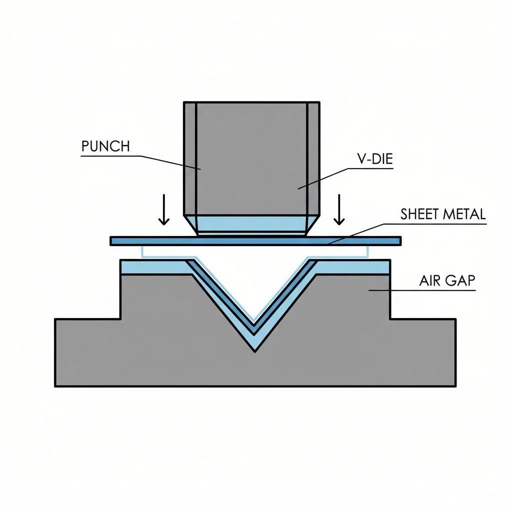
Air bending remains one of the most popular cnc bending methods in sheet metal fabrication. Imagine a punch pressing down on your sheet metal, forcing it into a V-shaped die below. The key difference? The metal never fully contacts the bottom of the die. Instead, it bends around the die's edge while "floating" in the air gap.
This approach offers remarkable versatility. Because the punch doesn't force the material all the way down, you can achieve different bend angles using the same tooling simply by adjusting the punch depth. This flexibility reduces setup time and tooling costs significantly. However, air bending comes with a trade-off: springback. When you release the bending force, the metal naturally tries to return toward its original flat state. Experienced operators compensate by over-bending slightly, but this requires precise calculations.
Bottom bending, also called bottoming, takes a different approach. Here, the punch presses the sheet metal completely against the bottom of the V-shaped die. This full contact produces more accurate angles and significantly reduces springback compared to air bending. According to Monroe Engineering, bottoming is often preferred over air bending because of its higher level of accuracy and less recoil with the finished sheet metal.
When should you choose each method? Air bending works beautifully for thin to medium gauge materials where quick setups and lower tooling costs matter. Bottoming shines when you're working with thicker materials or need tight tolerances that leave no room for springback-related errors.
When to Use Roll Bending and Rotary Methods
What if your project requires curves instead of sharp angles? That's where roll bending enters the picture. This technique uses three rotating rollers arranged in a pyramid configuration, with one roller on top and two positioned below. As sheet metal passes through this arrangement, the rollers gradually shape it into curved or cylindrical forms.
Roll bending excels at creating larger shapes like pipes, tubes, or architectural components. Think building facades with sweeping curves, cylindrical tanks, or structural arcs for bridges. The process handles longer sheets and plates that other methods simply cannot accommodate, making it indispensable for construction and architectural applications.
Rotary bending, on the other hand, specializes in forming tight radii and smooth curves without deforming the material's surface. A rotating bending tool moves around the sheet metal to create consistent curves. This method proves particularly valuable when you need aesthetically perfect results, like automotive body panels or aerospace components requiring smooth, uniform curves.
The bend radius, the smallest curve that can be formed without cracking or weakening the metal, becomes critical here. According to Dainsta, the minimum bend radius generally equals four times the sheet thickness. Rotary bending can often achieve tighter radii than conventional methods while preserving surface quality.
Press Brake Operations and Coining Techniques
Press brakes serve as the workhorses behind most metal sheet bending operations. These machines use hydraulic, mechanical, or servo-electric systems to drive a punch into a die, creating controlled bends. Modern cnc sheet metal bending machines take this further by automating the entire process, delivering multiple bends with minimal human intervention and exceptional repeatability.
Coining represents the most precise technique in the press brake family. Unlike air bending, coining uses tremendous force, up to 30 times more pressure, to completely compress the sheet metal between punch and die. This extreme pressure permanently deforms the metal into the exact shape of the tooling, virtually eliminating springback.
Why isn't coining used for everything? Cost. The massive forces involved require heavier equipment, specialized tooling, and more energy consumption. Coining makes economic sense for applications demanding extremely sharp angles, high-quality detailed parts, or materials that exhibit significant springback with other methods. Electronics enclosures and medical device components often benefit from this precision.
Springback compensation deserves special attention here. Every metal bending process must account for the material's elastic recovery. Operators calculate how much the metal will "spring back" after bending and adjust their approach accordingly. Coining minimizes this challenge through brute force, while air bending requires careful over-bending based on material properties and thickness.
| Technique Name | Best Applications | Material Thickness Range | Precision Level | Typical Equipment Used |
|---|---|---|---|---|
| Air Bending | General fabrication, brackets, enclosures, quick-turnaround projects | Thin to medium gauge (0.5mm - 6mm) | Moderate (±1° typical) | CNC press brakes, hydraulic press brakes |
| Bottom Bending | Automotive parts, structural components requiring tight tolerances | Medium to thick gauge (1mm - 12mm) | High (±0.5°) | Hydraulic press brakes, mechanical press brakes |
| Coining | Electronics enclosures, medical devices, intricate detailed parts | Thin to medium gauge (0.3mm - 4mm) | Very High (±0.25°) | Heavy-duty hydraulic press brakes with precision tooling |
| Roll Bending | Pipes, tubes, cylindrical tanks, architectural curves | Variable (0.5mm - 25mm+) | Moderate to High | Three-roll benders, pyramid roll machines |
| Rotary Bending | Automotive panels, aerospace parts, components requiring smooth curves | Thin to medium gauge (0.5mm - 6mm) | High | Rotary draw benders, CNC rotary machines |
| Wipe Bending | Deep bends, heavy-duty construction components, thick materials | Medium to thick gauge (2mm - 15mm) | Moderate to High | Wipe die press brakes, specialized forming equipment |
Understanding these sheet bending methods transforms how you communicate with cnc bending services providers. Instead of simply requesting "a bent part," you can now discuss whether air bending's speed or bottoming's precision better serves your application. You'll recognize when roll bending makes sense for curved components and why coining justifies its premium cost for critical precision work.
Of course, technique selection only tells part of the story. The material you choose dramatically influences which methods work best and what quality outcomes you can expect. Let's explore how different metals behave during the bending process.
Choosing the Right Metal for Your Bending Project
Here's something most providers assume you already know: different metals behave dramatically differently during bending. The aluminum bracket that forms beautifully might crack if you tried the same approach with hardened stainless steel. Understanding how each material responds to bending forces helps you make smarter decisions when requesting quotes and evaluating fabrication partners.
Three key material properties determine bending success: ductility (how much the metal can stretch before breaking), tensile strength (resistance to being pulled apart), and grain direction (the microscopic crystal orientation within the metal). Let's examine how these factors play out across the most common materials.
Steel and Stainless Steel Bending Characteristics
Mild steel remains the workhorse of steel sheet bending operations for good reason. With a yield strength around 250 MPa and excellent formability, it bends predictably without cracking. You'll find mild steel grades like A36 and 1018 in brackets, structural components, cabinets, and frames across virtually every industry.
Stainless steel presents more challenges. Its higher strength and greater elastic properties mean significantly more springback after the bending force releases. When you bend stainless to 90°, the actual angle might end up closer to 92° without proper compensation. According to 1CUTFAB, high-strength materials like stainless steel exhibit more springback than softer metals because they can store more elastic energy during deformation.
The solution? Experienced fabricators use larger bend radii for stainless, typically at least 1.5 times the material thickness. Annealed grades like 304L and 316L offer improved bendability compared to work-hardened versions. If your project demands tight tolerances with stainless steel, expect your fabrication partner to employ overbending techniques or bottoming methods to counteract springback.
Working with Aluminum and Copper Alloys
Wondering how to bend aluminum sheet metal without cracking it? The answer lies in understanding alloy selection and grain structure. Bendable aluminum sheet metal like 1100 and 3003 series alloys features extremely high ductility with elongation exceeding 30% and low yield strength (34-100 MPa). These soft alloys form beautifully into architectural panels, HVAC components, and electronic enclosures.
However, aluminum bending requires attention to grain orientation. As Inductaflex research explains, bending aluminum across the grain (perpendicular to the rolling direction) generally produces better results with fewer crack risks than bending along the grain. This directional behavior, called anisotropy, becomes especially critical when forming custom bent aluminum parts with tight radii.
Fine-grained aluminum bends more consistently and resists cracking better than coarse-grained material. Coarse grains can cause visible surface defects known as "orange peel" texture, while fine grains preserve smoother finishes. When sourcing bendable aluminum sheet metal for critical applications, consider requesting mill certificates that include grain size information.
Copper stands out as one of the easiest metals to bend, with elongation exceeding 40% and yield strength around 70-100 MPa. Its exceptional ductility makes it perfect for small-radius bends in electrical enclosures, telecommunications equipment, and heat exchangers. Brass alloys like C260 and C360 offer similar bendability with good springback control, making them popular choices for decorative hardware, instrument components, and valve assemblies.
Material Thickness and Bend Quality Relationships
Thickness dramatically influences bending behavior. Thicker sheets generally experience less springback because they undergo more uniform deformation throughout their cross-section. According to fabrication experts, thin sheets are more flexible and therefore more prone to rebound after bending.
The relationship between thickness and minimum bend radius follows a predictable pattern. Most metals require a minimum inside bend radius of at least one times the material thickness for softer materials and up to four times thickness for harder alloys. Attempting tighter radii risks cracking, especially on the outer surface where tensile stress concentrates.
Consider this practical example: bending aluminum sheet at 2mm thickness across the grain might allow a 2mm inside radius, while the same bend along the grain might require 4mm radius to prevent cracking. These material-specific considerations directly impact your part design and manufacturing costs.
| Metal Type | Bendability Rating | Springback Tendency | Minimum Bend Radius | Common Applications |
|---|---|---|---|---|
| Aluminum 1100 | Excellent | Low | 0.5-1× thickness | Signs, covers, decorative panels |
| Aluminum 3003 | Excellent | Low | 0.5-1× thickness | HVAC components, sheet metal work |
| Mild Steel A36 | Very Good | Moderate | 1× thickness | Frames, brackets, enclosures |
| Stainless 304L | Good (Annealed) | High | ≥1.5× thickness | Food equipment, medical devices, structural panels |
| Copper C110 | Excellent | Very Low | 0.5× thickness | Electrical, decorative, plumbing |
| Brass C260 | Very Good | Low-Moderate | 1× thickness | Hinges, nameplates, valves |
When requesting quotes for bending sheet metal projects, communicate your material specifications clearly. Include the alloy grade, temper condition, thickness, and grain direction requirements if critical. A knowledgeable fabrication partner will factor these variables into their process planning, tooling selection, and springback compensation calculations.
Understanding material behavior is just one piece of the puzzle. To communicate effectively with any provider and evaluate quotes accurately, you'll need to speak their language. Let's decode the essential terminology that separates informed buyers from confused ones.
Essential Metal Bending Terminology Decoded
Ever reviewed a quote from a metal bending company and felt like you were reading a foreign language? Terms like K-factor, bend allowance, and neutral axis get thrown around constantly, yet most providers never explain what they actually mean. This knowledge gap puts buyers at a disadvantage when evaluating proposals and communicating design requirements.
Understanding the metal bending process terminology transforms you from a passive recipient of quotes into an informed partner who can ask intelligent questions and catch potential issues before they become costly mistakes. Let's break down the essential terms that drive every sheet metal bend calculation.
K-Factor and Bend Allowance Calculations
The K-factor might be the most important number you've never heard of. It's a ratio that describes where the neutral axis sits within your material during bending, expressed as a decimal between 0 and 1. According to SendCutSend's engineering resources, the K-factor shows how much the neutral axis moves off center during a metal bend.
Why does this matter? Because the K-factor directly determines how your flat pattern dimensions translate into finished part dimensions. Softer metals like aluminum typically have K-factor values around 0.4, while harder materials like steel and stainless steel run closer to 0.45. These seemingly small differences significantly impact your final part accuracy.
Bend allowance builds directly on the K-factor concept. It represents the arc length of the neutral axis through the bend, essentially telling you how much extra material length the bend creates. The process of bending stretches material along this neutral axis, and bend allowance quantifies that stretch.
The bend allowance formula incorporates your bend angle, inside radius, material thickness, and K-factor:
Bend Allowance = Angle × (π/180) × (Bend Radius + K-Factor × Thickness)
When you know your flat material size and want to calculate finished flange lengths after bending, bend allowance provides the answer. This calculation ensures your sheet metal bends end up exactly where you need them.
Understanding Neutral Axis in Metal Forming
Imagine bending a piece of sheet metal. The inside surface compresses while the outside surface stretches. Somewhere between these two surfaces exists an imaginary line that experiences neither compression nor tension. That's the neutral axis.
Here's what most explanations miss: the neutral axis doesn't stay centered during bend processing. As Eabel's fabrication guide explains, the neutral axis shifts toward the inside of the bend based on material properties, thickness, and bending method. This shift is precisely what the K-factor quantifies.
Understanding the neutral axis position becomes critical when you need tight dimensional control. If your calculations assume the neutral axis stays centered (K-factor of 0.5), but your material actually shifts it inward (K-factor of 0.4), your finished parts will be slightly larger than intended. For precision applications, this difference matters enormously.
Bend Deduction and Its Impact on Part Dimensions
While bend allowance tells you what gets added during bending, bend deduction tells you what to subtract from your flat pattern. Think of it as the flip side of the same coin.
Here's a practical example from SendCutSend's calculations: if you want a final part with a 6-inch base and two 2-inch flanges, you might assume you need a 10-inch flat pattern (6 + 2 + 2). However, the bending process stretches material, so your actual flat pattern needs to be shorter. For 0.080-inch thick 5052 aluminum with 90° bends, each bend deduction works out to approximately 0.127 inches. Your corrected flat pattern becomes 9.745 inches.
The bend deduction formula builds on bend allowance:
Bend Deduction = 2 × (Bend Radius + Thickness) × tan(Angle/2) − Bend Allowance
When reviewing quotes or preparing designs for a metal bending company, understanding bend deduction helps you verify that flat pattern dimensions will produce the finished geometry you actually need.
| Term | Definition | Practical Relevance |
|---|---|---|
| K-Factor | Ratio defining neutral axis position relative to material thickness (typically 0.3-0.5) | Determines accuracy of flat pattern calculations; varies by material type and bending method |
| Bend Allowance | Arc length of neutral axis through the bend; represents material stretch during forming | Added to flat pattern length; essential for calculating finished flange dimensions |
| Bend Deduction | Amount subtracted from total flange lengths to calculate correct flat pattern size | Ensures flat pattern produces correct finished dimensions; critical for design accuracy |
| Neutral Axis | Imaginary line within material that neither stretches nor compresses during bending | Foundation for all bend calculations; position shift determines K-factor value |
| Inside Radius | Radius of the inner curve at the bend; determined by tooling and material properties | Affects bend allowance calculations; smaller radii increase cracking risk |
| Outside Radius | Inside radius plus material thickness; represents the outer bend surface curve | Used for clearance calculations and assembly fit verification |
| Flange Length | Distance from the bend line to the edge of the material | Must meet minimum requirements for proper tooling engagement; affects part strength |
| Setback | Distance from bend line to the tangent point of the radius | Critical for flat layout accuracy and proper tool positioning |
Armed with this terminology, you can now engage meaningfully when a fabricator discusses bend processing parameters or questions your design specifications. You'll recognize when K-factor assumptions might affect your part dimensions and understand why bend deduction calculations matter for fit and assembly.
Of course, knowing the language is just the beginning. The equipment used to execute these precise calculations plays an equally important role in determining what's possible for your project. Let's explore the technology behind modern metal bending operations.
Metal Bending Equipment and Technology Explained
When you request a quote from a metal bending company, you'll often see references to press brakes, CNC machines, and tonnage ratings. But what do these terms actually mean for your project? The equipment used to form your parts directly influences quality, cost, and lead time. Understanding this landscape helps you evaluate whether a fabricator's capabilities truly match your requirements.
The sheet metal bending equipment world spans a wide spectrum, from manually operated machines suited for simple jobs to sophisticated cnc sheet metal systems capable of producing complex multi-bend parts with sub-degree accuracy. Here's the equipment you'll encounter:
- CNC press brakes: Computer-controlled machines offering programmable precision and automated bend sequences
- Hydraulic press brakes: Force-driven machines using hydraulic cylinders for consistent pressure throughout the stroke
- Mechanical press brakes: Flywheel-powered machines delivering fast cycling for high-volume production
- Roll bending machines: Three-roller systems for creating curves, cylinders, and large-radius shapes
- Rotary draw benders: Specialized equipment for tube and pipe bending with tight radii and minimal deformation
CNC Press Brakes and Their Precision Advantages
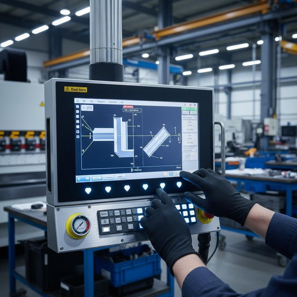
Ever wonder how fabricators achieve ±0.5° bend accuracy across thousands of identical parts? The answer lies in CNC technology. A modern cnc sheet metal bending machine uses computer numerical control to automate every aspect of the bending process, from backgauge positioning to punch depth and dwell time.
According to Durmark Machinery, CNC press brakes provide superior precision and repeatability because digital positioning systems and programmable backgauges eliminate the variability inherent in manual setups. Operators program exact angles, dimensions, and bending sequences, reducing human error and ensuring consistent quality across batches.
What makes metal cnc bending particularly powerful for complex parts? Modern systems can store hundreds of part programs, automatically calculate bend sequences, and even display 3D simulations before the first bend occurs. Some advanced sheet metal bending machines feature laser angle measuring systems that automatically compensate for springback in real-time, achieving first-pass accuracy that traditional methods simply cannot match.
For aerospace, automotive, and electronics applications demanding tight tolerances, CNC press brakes deliver capabilities that justify their higher investment. Features like touchscreen interfaces, automatic tool changes, and IoT connectivity for remote diagnostics transform these machines into smart manufacturing hubs capable of complex multi-bend parts with consistent repeatability across production runs exceeding 10,000 cycles.
Manual Versus Automated Bending Equipment
Not every project requires the sophistication of CNC automation. Understanding when manual and automated steel bending equipment each make sense helps you match your requirements to the right fabricator capabilities.
Hydraulic press brakes use hydraulic cylinders to move the ram, applying consistent force throughout the entire stroke. This consistency makes them ideal for heavy-duty bending tasks where uniform pressure matters more than programming flexibility. According to industry analysis, hydraulic press brakes offer decent accuracy but depend significantly on operator skill. They're more affordable upfront and work well for simpler, repetitive tasks with moderate precision requirements.
Mechanical press brakes use a flywheel to store energy and deliver it rapidly during the bending stroke. Their fast cycling speeds make them efficient for high-volume production of simple parts. However, they offer less control over stroke speed and force compared to hydraulic systems, limiting their suitability for precision work.
Here's how the choice breaks down in practice:
| Equipment Type | Best For | Precision Level | Setup Time | Cost Consideration |
|---|---|---|---|---|
| CNC Press Brake | Complex parts, tight tolerances, high-mix production | ±0.5° or better | Quick (programmed) | Higher upfront, lower per-part |
| Hydraulic Press Brake | Heavy-duty bending, moderate precision, simpler parts | ±1° typical | Moderate | Lower upfront, higher labor |
| Mechanical Press Brake | High-volume simple parts, fast cycling requirements | ±1-2° | Moderate | Moderate upfront and operating |
| Roll Bending Machine | Cylinders, curves, architectural shapes, large radii | Varies by setup | Moderate to long | Specialized application |
| Rotary Draw Bender | Tube/pipe bending, tight radii, smooth curves | High with proper tooling | Tooling-dependent | Tooling investment required |
A metal sheet bender machine suited for prototyping a handful of parts differs dramatically from production equipment optimized for 50,000-piece runs. When evaluating fabricators, ask about their specific equipment models and how those capabilities align with your volume, complexity, and tolerance requirements.
Understanding Tonnage Requirements for Your Project
Tonnage determines whether a press brake can successfully form your part without damaging the machine or producing defective bends. This specification represents the maximum force the equipment can apply, and getting it wrong leads to costly problems.
According to RMT US research, the primary factors affecting tonnage requirements include material thickness, bend length, and tensile strength. The relationship is non-linear: double the sheet thickness and you'll need approximately four times the tonnage. For carbon steel, fabricators typically calculate tonnage using this formula: Tonnage = (55 × thickness² × bend length) ÷ die width.
Material matters enormously here. The same research indicates that stainless steel at 12mm thickness requires around 73% more tonnage compared to similar-thickness aluminum because of its much higher yield strength. High-strength materials like AR400 steel (with tensile strength around 500 MPa) demand robust equipment with frames at least 30mm thick and dual-circuit hydraulic systems.
What happens when tonnage falls short? Incomplete bends, inconsistent angles, and potential equipment damage. Conversely, excessive tonnage wastes energy and increases operating costs. When discussing projects with a metal bending company, provide complete material specifications including alloy grade, thickness, and tensile strength so they can match your requirements to appropriate equipment.
For demanding applications, modern CNC systems incorporate real-time monitoring that tracks punch tip deformation and automatically adjusts parameters. This adaptive capability helps maintain <0.1mm repeatability even during extended production runs where tool wear would otherwise cause dimensional drift.
With the right equipment selected and tonnage requirements understood, the next critical factor becomes your part design itself. Even the most advanced machinery cannot compensate for designs that ignore fundamental bending constraints. Let's explore how to prepare parts that bend successfully the first time.
Designing Parts for Successful Metal Bending
Here's a reality check most fabricators won't share upfront: design errors cause more project delays and cost overruns than equipment limitations or material issues combined. A perfectly engineered part that ignores bending constraints becomes an expensive lesson in redesign cycles. The good news? Forming sheet metal successfully follows predictable rules, and understanding them before you submit CAD files saves tremendous headaches downstream.
When you're creating custom sheet metal parts, thinking like a manufacturer transforms your designs from "theoretically possible" to "production-ready." Let's walk through the critical design considerations that separate smooth projects from troubled ones:
- Minimum flange length requirements: Flanges too short slip in tooling and produce inconsistent bends
- Hole-to-bend distance rules: Features placed too close to bend lines distort or tear during forming
- Relief notch placement: Strategic cutouts prevent cracking at bend intersections and edges
- Grain direction orientation: Bending across versus along grain dramatically affects crack resistance
- Bend sequence planning: Complex parts require specific forming orders to avoid tool interference
Minimum Flange Lengths and Hole Placement Rules
Imagine trying to grip a piece of paper by its edge to fold it precisely. Too little material to hold, and the fold wanders unpredictably. The same principle applies to custom sheet metal bending: flanges need sufficient length for tooling to engage securely.
According to Okdor's fabrication guidelines, flanges should be at least three to four times the material thickness as a baseline. For a 2mm sheet, this translates to a minimum flange length of 6-8mm. Anything shorter risks slipping in tooling, distortion along the bend line, or inconsistent results in production.
Here's the quick reference you'll want bookmarked:
| Material Thickness | Recommended Minimum Flange Length |
|---|---|
| 1 mm | 3-4 mm |
| 2 mm | 6-8 mm |
| 3 mm | 9-12 mm |
| 4 mm | 12-16 mm |
Hole placement follows equally strict rules. When holes sit too close to bend lines, the material stretches unevenly during forming, causing holes to elongate into ovals or even crack through to the edge. Keep holes at least 2-3 times the sheet thickness away from any bend line.
Consider this practical example from industry experience: a 1.5mm aluminum enclosure had mounting holes placed only 1mm from the bend. On the shop floor, those holes elongated, fasteners couldn't seat properly, and the entire prototype batch required scrapping. The fix was simple but expensive: redesigning with 4mm clearance eliminated the problem entirely.
Planning Bend Sequences for Complex Parts
What happens when your design requires four, five, or six bends in close proximity? Complexity multiplies quickly. Each additional bend adds springback variation, tolerance stack-up, and potential tool access conflicts. According to fabrication experts, more than 4-5 bends in one part often requires custom setups, and flanges spaced less than three times material thickness apart may block tooling entirely.
The order in which bends are performed, your bending sequence, can make or break manufacturability. Improper sequencing leads to distortion, misalignment, or situations where previously formed features physically prevent access for subsequent bends. Think of it like origami: fold in the wrong order and you can't complete the design.
This is where bypass notches sheet metal forming purpose becomes critical. These strategic cutouts at bend intersections allow material to flow without building up stress concentrations that cause tearing. When two perpendicular bends meet at a corner, a bypass notch (sometimes called a bend relief) provides clearance for the material to deform without fighting itself.
Sizing bend reliefs correctly prevents corner cracks while maintaining structural integrity. According to design guidelines, relief width should approximately equal material thickness, while length should be at least equal to the bend radius (or 1.5 times thickness for thicker sheets). A simple 2mm × 2mm slot in your CAD model costs nothing but prevents cosmetic flaws and uncontrolled shop fixes.
When should you definitely include reliefs?
- Flange ends close to an edge
- Short flange lengths (less than 3× thickness)
- Tight inside radii (approximately equal to thickness or less)
- Harder alloys like stainless steel or high-strength steels
File Formats and Design Specifications That Work
Even the most perfectly designed part fails if your metal bending company can't accurately interpret your files. File preparation errors, from incorrect scaling to missing specifications, cause delays that could have been avoided with proper documentation.
According to Five Flute's engineering resources, sheet metal fabrication requires multiple manufacturing processes, and proper file preparation speeds up both quoting and production. The first step? Ask your manufacturer what file formats they prefer for each process stage. This reduces file conversion workload, which is often a source of mistakes (anyone who has received a 1:2 scaled down set of flat patterns will shudder when they read this).
As a best practice for metal fabrication and bending projects, include these deliverables:
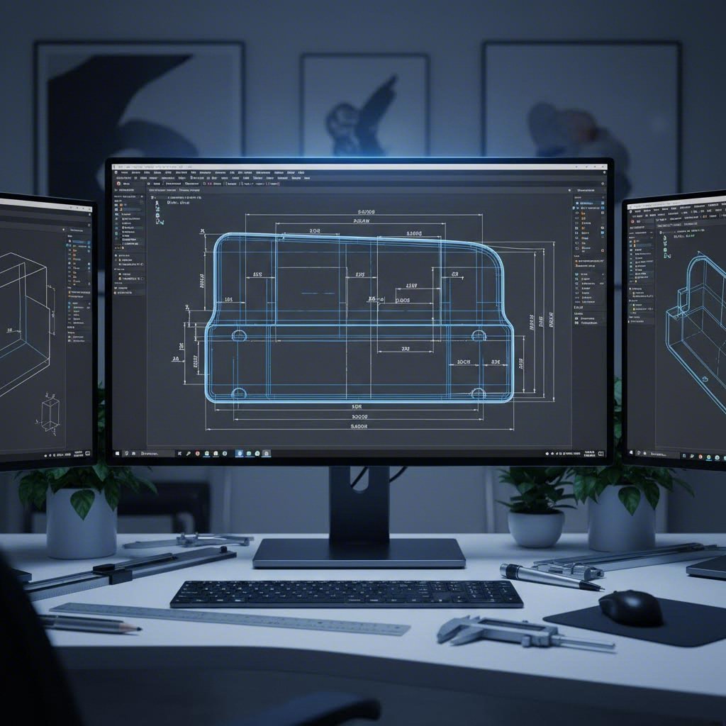
- Fully dimensioned 2D PDF drawing: Include all bends, holes, countersinks, flanges, and formed features with dimensions to virtual intersection points
- Reference 3D file (STEP format): Allows manufacturers to verify geometry and check for interference issues
- DXF flat pattern file: Remove all annotations and include only the easily selectable part profile for CAM programming
- Material and grain direction callouts: Especially critical for stainless steel and aluminum alloys with anisotropic properties
One crucial warning about flat patterns: the exact 2D geometry needed to create an accurate formed part may differ significantly from your CAD output. Different K-factors, bend allowances, and equipment variations mean manufacturers often iterate flat patterns until each bend falls within spec. According to engineering best practices, your flat pattern should be treated as reference geometry rather than a production-ready profile.
Common design mistakes that increase costs and delay projects include:
- Specifying bend radii smaller than material thickness (cracking risk)
- Using CAD software defaults meant for machined parts rather than sheet metal
- Mixing different radii unnecessarily (requires multiple tool setups)
- Over-tolerancing non-critical features (adds inspection cost without functional benefit)
- Ignoring grain direction requirements for anisotropic materials
When preparing sheet metal design services deliverables, dimension to virtual intersection points and show included bend angles. This ensures universal interpretation regardless of actual bend radius as formed. And remember: tight tolerances should only apply to features critical for fit or function. Calling out ±0.1mm across all features makes parts unnecessarily expensive without improving assembly quality.
With bending-ready designs in hand, the next question becomes: how do you verify that finished parts actually meet your specifications? Quality control processes separate reliable fabricators from those who hope for the best. Let's examine what professional inspection really involves.
Quality Control in Professional Metal Bending
Here's what separates world-class precision metal bending from "good enough" fabrication: systematic quality verification at every stage. Most providers mention quality in their marketing, but few explain what professional inspection actually involves. When your bent parts arrive, how do you know they meet specifications? More importantly, how does a reliable metal bending service ensure defects never leave their facility?
According to Weaver Precision Fabrication, a fabricator serving robotics and automation industries, "Quality is a cornerstone of our business. Most of our customers are 'dock to stock' with no incoming inspection of our parts, so it is vital that we ship good parts!" This dock-to-stock expectation, where customers trust parts are correct without re-inspecting them, defines the standard professional sheet metal bending services must meet.
Inspection Methods for Bent Metal Parts
Precision bending demands precision measurement. Professional fabricators deploy multiple inspection techniques tailored to different quality checkpoints throughout production:
Coordinate Measuring Machines (CMMs) represent the gold standard for complex geometry verification. These precision instruments use touch probes to collect 3D coordinate data from parts, capable of measuring complex geometries with micron-level accuracy. According to IPQC, CMMs compare measured points against CAD models, generating comprehensive deviation reports that identify exactly where dimensions fall outside tolerance.
Angle verification addresses the most critical aspect of any bent part. Traditional protractors have largely given way to digital angle finders and automated bend indicator systems. Some advanced press brakes now incorporate built-in angle measurement sensors that verify bends in real-time, automatically compensating for springback before the part ever leaves the machine.
Dimensional checking covers the full spectrum of part features. Professional inspection facilities use calibrated equipment including:
- Digital and dial calipers for length, width, and feature measurements
- Micrometers for precise thickness verification
- Digital height gauges for surface profile measurements
- Pin gauges and taper gauges for hole diameter verification
- Thread gauges for tapped hole inspection
- Surface plates and straight edges for flatness verification
Modern optical measurement systems add another layer of capability. According to industry sources, vision systems can process hundreds of measurements in seconds, comparing them against CAD models with micron-level precision while eliminating operator influence and providing complete surface analysis.
Understanding Tolerance Specifications
What tolerance should you expect from a professional cnc bending shop? The answer depends on your application, but here's a realistic baseline: precision metal bending typically achieves ±0.5° angular accuracy and ±0.25mm dimensional accuracy on well-designed parts.
Tolerance specifications fall into several categories:
- Angular tolerance: How close the bend angle matches specification (±0.5° to ±1° typical)
- Dimensional tolerance: Overall part dimensions including flange lengths and hole positions
- Geometric tolerance: Form characteristics like flatness, straightness, and parallelism
- Position tolerance: Location of features relative to datums and each other
First article inspection (FAI) plays a critical role in validating tolerance compliance before production begins. This comprehensive measurement of the first produced part verifies that tooling, machine setup, and material all work together to achieve specifications. According to fabrication experts, both an operator and a quality inspector independently scrutinize first-off parts at every operation, and both must sign off before the part can advance.
For production runs, statistical process control (SPC) monitors quality continuously rather than relying solely on final inspection. SPC software analyzes measurement data to identify trends and prevent defects before they occur. If measurements start drifting toward tolerance limits, operators can adjust parameters before parts actually fail specification.
Certification Standards That Matter
When evaluating steel bending services, certifications provide objective evidence of quality system maturity. These aren't just wall decorations; they represent audited, documented commitment to consistent processes:
- ISO 9001: The universal quality management standard applicable across industries. According to Hartford Technologies, this certification delineates prerequisites for a robust quality management system, confirming that products comply with customer expectations and regulatory mandates.
- IATF 16949: Essential for automotive applications. This global standard builds upon ISO 9001 with additional requirements for product design, production processes, improvement, and customer-specific standards specific to automotive supply chains.
- AS9100: Mandatory for aerospace work. This certification confirms parts meet the safety, quality, and high standards required by aviation, addressing the highly specific and technical requirements where precision directly impacts safety.
- ISO 13485: Required for medical device components, ensuring designs and manufacturing prioritize patient safety through rigorous inspection protocols.
Beyond certifications, ask potential fabricators about their specific quality practices. Do they perform dual independent inspections at each operation? Is all measurement equipment regularly calibrated and documented? Can they provide material certifications and full traceability for your parts?
According to industry experience, the cost of quality failures extends beyond scrap material. One fabricator reports that customers charge $200 per rejection just to cover their paperwork costs. Investing a few extra seconds of analysis on each part prevents thousands of dollars in rejection costs and protects the supplier-customer relationship.
Quality verification establishes that your parts meet specifications, but what happens when they don't? Understanding common bending defects and their prevention helps you work proactively with fabricators rather than reactively addressing failures after delivery.
Common Metal Bending Defects and How to Prevent Them
So you've designed your part correctly, selected the right material, and chosen a capable fabricator. What could possibly go wrong? Plenty, actually. Even experienced shops encounter defects that compromise part quality, increase costs, and delay deliveries. The difference between good and great fabricators lies in how they anticipate and prevent these issues before your parts ever reach inspection.
Understanding these common sheet metal bending methods failures transforms you from a passive customer into a knowledgeable partner who can ask the right questions and recognize quality problems early. Let's examine the defects that plague bent sheet metal production and, more importantly, how do you bend metal without encountering them.
Preventing Springback in Precision Parts
Remember that frustrating moment when you release a bent paperclip and it springs partially back toward its original shape? The same phenomenon occurs with every bend metal operation. Springback happens because metal stores elastic energy during bending and releases it when the forming force is removed.
According to JLCCNC's fabrication research, springback is a common frustration in sheet metal forming defects, especially with high-tensile alloys. You form the perfect angle, hit cycle stop, and the part springs slightly out of spec. The material naturally tries to return to its original shape once forming pressure releases.
How much springback should you expect? Material properties determine the answer:
- 304 and 316 stainless steel: 6-8° typical springback
- 6061-T6 aluminum: 2-3° average
- High-strength low-alloy (HSLA) steels: 8-10° or higher
- Mild carbon steel: 2-4° typical
Experienced fabricators employ several proven compensation techniques:
Overbending remains the most common approach. If your target angle is 90° and the material exhibits 6° springback, the operator programs a bend to 84°, allowing elastic recovery to bring the part to the correct final angle. According to Accurl's technical resources, once you dial in the compensation through test bends, the results become dead accurate.
Bottoming and coining reduce springback by forcing material completely against the die surface. This technique applies significantly more force than air bending, plastically deforming the material to lock in the angle. For materials with high elasticity, bottoming often proves more reliable than calculating compensation factors.
Die geometry adjustment offers another avenue. Decreasing the V-die width-to-thickness ratio from 12:1 to 8:1 has been shown to cut springback by up to 40%. Narrower dies concentrate force at the bend point, reducing elastic recovery.
Avoiding Cracking and Surface Defects
Few things ruin a part faster than cracks appearing right at the bend line. According to fabrication experts, cracking is one of the most common sheet metal bending defects, showing up when the material simply cannot handle the stress.
What causes bended metal to crack during forming? Several factors combine:
- Bend radius too small for the material thickness
- Bending along rather than across the grain direction
- Low-ductility materials like hard aluminum or cold-rolled steel
- Over-bending without accounting for material limits
- Work-hardened edges from prior processing
Prevention starts with proper bend radius selection. According to deformation research, the inner bend radius should be at least 1-1.5 times the material thickness as a general rule. For more ductile materials, smaller radii may work; for harder alloys, larger radii become essential.
Grain direction matters enormously. Bending perpendicular to the grain (across the rolling direction) helps minimize cracking because the material's crystalline structure stretches more uniformly. When bending along the grain, the stretched outer surface tends to separate along grain boundaries.
For brittle or work-hardened metals, consider preheating. According to press brake specialists, if ambient temperature falls below 10°C, preheating material to 150°C improves ductility and prevents micro-fractures at the bend.
Surface defects present different challenges. Scratches, tool marks, and surface damage result from contaminated tooling surfaces, incorrect die clearances, or debris in the bending zone. According to industry data, up to 5% of rework in sheet metal fabrication links directly to overlooked contamination or die damage.
Professional shops prevent surface damage through:
- Cleaning dies before every setup
- Using polished punches with surface roughness of Ra ≤ 0.4 µm
- Applying proper lubricants suited to the specific material
- Installing UHMW-PE film inserts (0.25mm thickness) for protecting soft metals
- Regular inspection and re-honing of worn die surfaces
Solutions for Wrinkling and Distortion Issues
Wrinkling might not break your part, but it destroys the clean, professional appearance and can interfere with assembly fitment. According to fabrication analysis, wrinkling occurs when compressive forces bunch up material along the inside of the bend, especially with long, unsupported flanges.
The primary causes include:
- Flange length too long without proper support
- Poor die design that doesn't control material flow during forming
- Insufficient blank holder force in forming operations
- Material too thin for the bending configuration
Solutions focus on controlling material movement during the bend. Reducing flange length eliminates the unsupported area prone to buckling. Using stiffer dies or adding restraining features controls the sheet during bending. Increasing blank holder force keeps the sheet taut and prevents bunching.
Warping, twisting, and bowing indicate uneven stress distribution during forming. According to technical resources, when bending force isn't uniformly applied, materials like mild steel or aluminum risk deforming unpredictably. Poor material support and excessive tonnage typically share the blame.
Prevention strategies include:
- Checking gib clearances (if exceeding 0.008 inches, the ram may track unevenly)
- Supporting long blanks with anti-sag arms, especially when blank length exceeds four times material width
- Distributing bending force evenly across the die length
- Verifying that tonnage settings match material requirements
| Problem | Cause | Prevention Method | Solution |
|---|---|---|---|
| Springback | Elastic recovery after bending force release; higher in stainless and HSLA steels | Calculate material-specific compensation; use appropriate die width ratios | Overbend by calculated amount; use bottoming or coining; reduce V-die width-to-thickness ratio from 12:1 to 8:1 |
| Cracking at Bend Line | Bend radius too tight; bending along grain; low-ductility material; work-hardened edges | Use minimum 1-1.5× thickness bend radius; orient grain perpendicular to bend; select ductile alloys | Increase bend radius; preheat brittle materials to 150°C; switch to annealed material grades |
| Surface Scratches/Marks | Contaminated tooling; worn die surfaces; debris in bending zone; excessive pressure | Clean dies before each setup; use polished punches (Ra ≤ 0.4 µm); apply appropriate lubricants | Install protective film inserts; re-hone or replace worn dies; reduce forming pressure where possible |
| Wrinkling | Compressive forces on inside of bend; unsupported flanges; thin material | Design appropriate flange lengths; use stiffer dies with restraining features | Reduce flange length; increase blank holder force; add pressure pads to control material flow |
| Warping/Twisting | Uneven stress distribution; asymmetric tool setup; incorrect gib clearance | Verify gib clearance ≤0.008 in; use anti-sag arms for long blanks; ensure symmetric loading | Re-shim guide rails; apply stress-relief annealing; distribute force evenly across die length |
| Dimensional Inaccuracy | Inaccurate press brake calibration; material thickness variation; wrong bend allowance calculations | Calibrate equipment regularly; verify material specs; use real-world bend test values | Recalibrate machine; adjust flat pattern based on actual bend tests; match tooling to part geometry |
Experienced metal bending companies anticipate these issues through systematic process control. Before production begins, they verify material specifications, select appropriate tooling, and run test bends to dial in compensation factors. During production, they monitor for signs of tool wear, material variation, and process drift that could introduce defects.
The difference shows in their approach to bendable sheet metal handling. Professional shops control material storage conditions to prevent moisture absorption and oxidation. They track material lot numbers for traceability. They document bend sequences and tooling setups so successful approaches can be replicated consistently.
When defects do occur, root cause analysis prevents recurrence. Was the material out of spec? Did tooling wear beyond acceptable limits? Did the operator skip a calibration check? Answering these questions transforms isolated problems into systematic improvements.
Understanding these common defects prepares you to evaluate fabrication partners more effectively. When you tour a facility, look for evidence of process control: calibrated measuring equipment, documented procedures, and operators who can explain their quality checkpoints. These indicators reveal whether a shop prevents defects proactively or simply sorts them out at final inspection.
Selecting the Right Metal Bending Company for Your Project
You've mastered the terminology, understand material behavior, and know what defects to watch for. Now comes the critical decision: which metal bending partner deserves your business? This choice impacts far more than individual part costs. According to LS precision manufacturing experts, your supplier directly affects your cost per piece, product quality, manufacturing efficiency, and brand reputation.
Whether you're searching for metal bending near me or evaluating global suppliers, the same fundamental criteria apply. A systematic evaluation approach separates reliable long-term partners from shops that create more problems than they solve. Let's walk through the factors that matter most.
- Equipment capabilities: CNC precision, tonnage range, and tooling library depth
- Material expertise: Proven experience with your specific alloys and thicknesses
- Industry certifications: ISO 9001, IATF 16949, AS9100, or ISO 13485 as applicable
- Prototyping speed: Ability to deliver functional samples within days, not weeks
- Production capacity: Scalability from prototypes to high-volume runs
- Engineering support: DFM analysis, quote accuracy, and technical communication
Evaluating Equipment and Capabilities
Imagine searching for sheet metal benders near me and finding three apparently similar shops. How do you distinguish between them? Equipment tells much of the story. According to MarcTech fabrication guidance, the equipment and technology a company uses can significantly impact the quality, precision, and efficiency of their work.
When evaluating a potential bend machine shop, focus on these equipment indicators:
- Press brake brand and age: Modern CNC press brakes from reputable manufacturers deliver repeatability that older equipment simply cannot match
- Tonnage range: Verify the shop can handle your material thickness requirements with appropriate force capacity
- Backgauge accuracy: Digital backgauge systems with ±0.1mm positioning accuracy ensure consistent flange lengths
- Tooling library: Comprehensive punch and die collections reduce setup costs and enable complex geometries
- Complementary equipment: Laser cutting, punching, and finishing capabilities under one roof streamline production
According to industry evaluation criteria, when evaluating a press brake, you should focus on repeatability positioning accuracy (±0.1mm or better for precision work), CNC system capability for springback compensation, and whether their equipment matches your complexity requirements.
Don't rely solely on marketing materials. As fabrication specialists recommend, pay attention to how well-maintained the fabrication facility appears. A clean, organized, and well-cared-for workspace indicates the company takes pride in its work and commits to quality control. If possible, conduct site visits to see equipment condition firsthand rather than trusting brochure photos.
What Turnaround Times and Pricing Reveal
Here's something most buyers overlook: a quote tells you more about a fabricator than any sales pitch. According to procurement experts, a clear and thorough quote is among the best proof of a manufacturer's level of professionalism and integrity.
Professional quotes break down costs transparently:
- Material costs: Sheet metal type, specification, and calculated loss
- Processing charges: Programming, cutting, and bending time
- Tooling charges: Depreciation or customization of dedicated tooling
- Surface treatment: Outsourced finishing like plating, painting, or anodizing
- Management fees: Overhead and reasonable profit margin
Watch out for quotes that are too generic or significantly lower than the industry average. According to manufacturing guidance, such quotes might intentionally avoid needed steps, tooling expenses, or not factor in additional expenses for minimal-volume requests. Those hidden costs surface later as modification fees, expediting fees, or special processing fees that blow your budget.
Turnaround time reveals operational efficiency. When you need metal bending services near me quickly, rapid quoting becomes essential. Professional shops with streamlined processes can deliver quotes within 12-24 hours because they've systematized their estimation workflows. Shops that take a week to quote often struggle with production scheduling too.
For automotive applications where supply chain speed matters, companies like Shaoyi (Ningbo) Metal Technology exemplify what rapid response looks like. Their 12-hour quote turnaround and 5-day rapid prototyping capabilities demonstrate the operational efficiency that separates responsive partners from sluggish ones.
Certifications and Industry Specializations That Matter
Certifications aren't just wall decorations. They represent audited, documented commitment to consistent processes that directly impact your project outcomes. When evaluating metal bending shops near me, match certifications to your industry requirements:
| Certification | Industry Application | What It Demonstrates |
|---|---|---|
| ISO 9001 | General manufacturing | Standardized quality management, continuous improvement culture |
| IATF 16949 | Automotive | Automotive-specific quality requirements, defect prevention focus |
| AS9100 | Aerospace | Safety-critical manufacturing controls, full traceability |
| ISO 13485 | Medical devices | Patient safety prioritization, rigorous inspection protocols |
According to quality evaluation standards, ISO 9001 certification gives direct proof of a manufacturer's intention toward process standardization and continuous improvement. It means the producer doesn't solely depend on experience but defines standardized management from order review through shipment.
For automotive chassis, suspension, and structural components, IATF 16949 certification is non-negotiable. This standard builds on ISO 9001 with additional requirements for product design, production processes, and customer-specific standards that automotive OEMs demand. Shaoyi Metal Technology carries this certification specifically because automotive applications require the systematic defect prevention and supply chain quality focus it represents.
Beyond certifications, look for demonstrated industry experience. According to fabrication selection criteria, an experienced company should have the technical expertise and specialized equipment to handle everything from simple parts to complex custom metal structures. They should show you a robust portfolio of past projects similar in scope and complexity to what you're looking to achieve.
The Value of DFM Support and Engineering Partnership
Here's what separates transactional vendors from true manufacturing partners: Design for Manufacturability (DFM) support. According to manufacturing expertise, superior equipment is a condition for superior production, but complete technical and process knowledge allows challenges to be resolved and DFM to be accomplished.
What does comprehensive DFM support look like in practice?
- Proactive design review: Engineers identify manufacturability issues before quoting, not after production fails
- Material recommendations: Guidance on optimal alloys and thicknesses for your application
- Tolerance optimization: Balancing precision requirements against cost implications
- Bend sequence planning: Ensuring complex parts can actually be formed without tool interference
- Cost reduction suggestions: Design modifications that maintain function while reducing manufacturing complexity
According to prototyping research, functional prototyping typically requires several prototypes to test specific functionalities and ensure the design meets performance requirements. Partners with rapid prototyping capabilities can deliver these functional samples in days rather than weeks, accelerating your development cycle significantly.
For automotive applications, Shaoyi Metal Technology demonstrates what comprehensive DFM support means in practice. Their engineering team reviews designs before quoting, identifies potential manufacturing challenges, and recommends optimizations that improve quality while reducing costs. Combined with 5-day rapid prototyping for chassis, suspension, and structural components, this approach accelerates automotive supply chains significantly.
Red Flags to Avoid When Choosing a Partner
Not every shop that shows up when you search sheet metal bending near me deserves your business. According to industry guidance, buyers often fall into common traps that translate into higher prices, longer lead times, and quality failures:
The low-price trap: Quotes significantly below market rate typically hide corners being cut. According to procurement experts, some suppliers offer lower prices by reducing material quality, omitting required operations, or concealing future costs. Require itemized quotes and compare based on quality, service, and price together.
Poor communication patterns: If a supplier is slow responding, communication is inadequate, or they cannot provide clear project timelines, weak management likely follows. Test communication efficiency before committing by asking for a dedicated project manager and standardized update processes.
Overpromising capabilities: Some suppliers promise everything without proper technical evaluation to support those claims. Request specific process plans and DFM analysis based on your drawings to verify reliability with technical details.
Outdated equipment: Aging or obsolete equipment cannot offer the stability and reliability modern applications demand. According to evaluation criteria, conduct site visits whenever feasible, focusing on machine brand, age, maintenance history, and tooling library depth.
Missing documentation: Dependence solely on verbal understanding provides no useful redress when problems arise. Have written contracts specifying technical standards, acceptance procedures, delivery obligations, payment terms, liability for breach, and intellectual property ownership.
The antidote to these pitfalls? Comprehensive evaluation and prudent decision-making. A good partner is more than a processor. They bring technical knowledge that reduces project risk and supports your long-term success. Whether you're developing automotive components requiring IATF 16949 compliance or aerospace parts demanding AS9100 traceability, the right metal bending company becomes a strategic extension of your manufacturing capabilities.
Frequently Asked Questions About Metal Bending Companies
1. What services does a metal bending company provide?
A metal bending company specializes in reshaping metal sheets, bars, and tubes into specific angles, curves, or profiles using controlled force. Services include design planning with bend allowance calculations, blank preparation through laser cutting or punching, CNC press brake operations, quality inspection, and finishing processes. They work with materials like steel, stainless steel, aluminum, copper, and brass for industries including automotive, aerospace, construction, and electronics.
2. What is the difference between air bending and bottom bending?
Air bending presses metal into a V-shaped die without full contact, allowing different angles with the same tooling by adjusting punch depth. It offers versatility and lower costs but requires springback compensation. Bottom bending forces the sheet completely against the die, producing more accurate angles with significantly reduced springback. Choose air bending for thin to medium gauge materials needing quick setups, and bottom bending for thicker materials or tight tolerance requirements.
3. How do I choose the right metal for my bending project?
Material selection depends on ductility, tensile strength, and grain direction. Mild steel bends predictably and suits general fabrication. Stainless steel requires larger bend radii due to higher springback. Aluminum alloys like 1100 and 3003 offer excellent bendability for enclosures and panels. Copper provides exceptional ductility for tight-radius bends. Consider bending perpendicular to grain direction for crack prevention, and maintain minimum bend radius of 1-1.5 times material thickness.
4. What certifications should I look for in a metal bending company?
ISO 9001 certification demonstrates standardized quality management for general manufacturing. IATF 16949 is essential for automotive applications, ensuring defect prevention and supply chain quality. AS9100 is mandatory for aerospace work with safety-critical manufacturing controls. ISO 13485 applies to medical device components. Companies like Shaoyi Metal Technology carry IATF 16949 certification specifically for automotive chassis, suspension, and structural components requiring systematic quality control.
5. How can I prevent common metal bending defects like springback and cracking?
Prevent springback by overbending to compensate for elastic recovery, using bottoming techniques, or reducing V-die width-to-thickness ratios. Avoid cracking by maintaining minimum bend radius of 1-1.5 times thickness, bending perpendicular to grain direction, and preheating brittle materials. Surface defects are prevented through clean tooling, polished punches, and proper lubrication. Professional fabricators anticipate these issues through material-specific process planning and systematic quality control.