 Small batches, high standards. Our rapid prototyping service makes validation faster and easier —

Manufacturing Dies Exposed: Cost Factors Your Supplier Won't Mention
What Is a Die in Manufacturing and Why It Matters
Ever wondered how thousands of identical car door panels roll off assembly lines with perfect precision? Or how your smartphone's intricate metal housing gets its exact shape every single time? The answer lies in one of manufacturing's most essential yet often overlooked tools: the manufacturing die.
A manufacturing die is a specialized tool designed to cut, shape, or form materials into precise configurations during mass production. Working in conjunction with a press, a die is used to transform raw materials—such as metal sheets, plastics, and rubber—into finished components with consistent accuracy and repeatability.
The Foundation of Precision Manufacturing
So, what is a die in manufacturing, and why should you care? Think of it as a highly engineered mold or template that applies force to raw materials, permanently altering their shape. Unlike simple cutting tools, dies are purpose-built for specific parts and can perform multiple operations simultaneously—cutting, bending, drawing, and forming—all in a single press stroke.
The concept is straightforward yet powerful. When you place a flat metal sheet between the upper and lower components of a die and apply pressure through a stamping press, the material takes on the exact shape engineered into that tooling. This process, known as die manufacturing, enables factories to produce millions of identical parts with tolerances measured in thousandths of an inch.
What makes manufacturing dies indispensable is their ability to maintain consistency across massive production volumes. According to industry standards, a well-designed die can produce hundreds of thousands—even millions—of parts before requiring significant maintenance or replacement.
From Raw Material to Finished Product
Imagine the journey of a simple metal bracket. It starts as a flat steel coil, gets fed into a stamping press equipped with a progressive die, and emerges seconds later as a precisely formed component ready for assembly. This transformation happens because the die contains all the geometric information needed to shape that part—every bend angle, every hole location, every contour.
What are dies used for in everyday products? The list is extensive:
- Automotive body panels, brackets, and structural components
- Electronic device housings and connectors
- Household appliance enclosures and internal parts
- Aerospace structural elements requiring extreme precision
- Medical device components demanding biocompatible finishes
Understanding what is die manufacturing matters because these tools directly influence three critical factors: part quality, production speed, and unit cost. A poorly designed die leads to defects, downtime, and wasted materials. A well-engineered manufacturing die delivers consistent quality at high speeds, dramatically reducing per-part costs as volumes increase.
For anyone involved in manufacturing decision-making—whether you're sourcing components, managing production, or evaluating suppliers—grasping how dies work provides the foundation for making smarter, more cost-effective choices. The chapters ahead will reveal the nine cost factors that significantly impact your bottom line, factors your current supplier may never have mentioned.
Types of Dies Used in Modern Manufacturing
Now that you understand what a manufacturing die is, the next question becomes: which type do you actually need? Choosing the wrong die for your application is one of the fastest ways to blow your budget—and it's a cost factor suppliers rarely discuss upfront. The reality is that die selection directly impacts everything from tooling investment to per-part production costs.
Manufacturing dies fall into three broad categories: cutting dies for material separation, forming dies for shape transformation, and multi-operation die systems that combine processes for efficiency. Let's break down each category so you can match the right tooling to your specific requirements.
Cutting Dies for Material Separation
What is die cutting at its core? It's the process of using a specialized cutting die to separate material into specific shapes and sizes. A die cutter applies force through precisely engineered edges to shear, punch, or trim raw stock into the geometry you need.
Cutting dies handle three primary operations:
- Blanking dies – Cut the entire perimeter of a part from sheet material, producing a finished flat piece or "blank" ready for further processing
- Piercing dies – Create internal holes, slots, or openings within a workpiece without removing the entire part from the stock
- Trimming dies – Remove excess material from previously formed parts, cleaning up edges and achieving final dimensional specifications
These operations form the foundation of most stamping die applications. Whether you're producing simple washers or complex automotive brackets, cutting operations typically represent the first step in transforming flat stock into functional components.
Forming Dies for Shape Transformation
While cutting dies separate material, forming dies reshape it without removal. Machine die cutting gets parts out of raw stock—forming dies give those parts their three-dimensional character.
Common forming operations include:
- Bending dies – Create angular features by folding material along a defined line, producing L-shapes, U-channels, and complex bent geometries
- Drawing dies – Transform flat blanks into cup-shaped or box-shaped components by pulling material into a cavity, essential for deep-drawn parts like automotive oil pans or electronic enclosures
- Coining dies – Apply extreme pressure to compress material into precise shapes with tight tolerances and fine surface details, commonly used for electrical contacts and decorative components
Forming dies typically require more engineering consideration than simple cutting tools. Material springback, surface finish requirements, and dimensional tolerances all influence die design complexity—and consequently, cost.
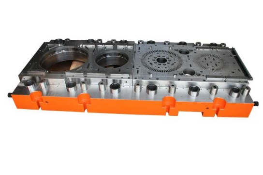
Multi-Operation Die Systems
Here's where things get interesting—and where understanding the differences can save you significant money. Multi-operation dies combine cutting and forming into integrated systems, but they do so in fundamentally different ways.
Progressive dies perform multiple operations in sequence as material feeds through a series of stations. Picture a metal strip advancing through the press—each stroke completes a different operation (piercing, forming, blanking) until the finished part drops off at the final station. According to Larson Tool, progressive dies are ideal for high-volume production of complex parts, though they carry higher upfront design and tooling costs.
Transfer dies also use multiple stations, but instead of keeping parts attached to a carrier strip, mechanical transfer systems move workpieces independently between operations. This approach excels for large or intricate parts that require more complex forming operations than progressive tooling can accommodate.
Compound dies execute multiple cutting operations simultaneously in a single press stroke. They're commonly used for flat parts requiring both blanking and piercing at the same time. As Standard Die notes, compound dies work well for general cutting applications but aren't recommended for forming and bending tasks since they often require more force.
Combination dies integrate both cutting and forming operations in a single tool, handling simultaneous actions like progressive dies but within a more compact setup. They're suitable for various applications across mining equipment, electronics, and appliances.
| Die Type | Primary Function | Best Applications | Complexity Level |
|---|---|---|---|
| Blanking Die | Cut complete part outlines from sheet stock | Flat components, washers, simple brackets | Low |
| Piercing Die | Create internal holes and openings | Parts requiring multiple hole patterns | Low to Medium |
| Bending Die | Form angular features and folds | Brackets, channels, enclosure components | Medium |
| Drawing Die | Create deep cup or box shapes | Housings, containers, automotive components | Medium to High |
| Compound Die | Multiple cutting operations in one stroke | Flat parts needing blanking and piercing | Medium |
| Progressive Die | Sequential operations across multiple stations | High-volume complex parts, automotive, aerospace | High |
| Transfer Die | Multi-station with independent part movement | Large or intricate components | High |
| Combination Die | Simultaneous cutting and forming | Medium complexity parts, electronics, appliances | Medium to High |
Understanding these types of dies isn't just academic—it directly impacts your cost structure. A progressive stamping die might cost significantly more upfront, but the per-part expense drops dramatically at high volumes. Conversely, a simple line die makes sense for lower quantities where tooling amortization won't justify complex automation.
The key takeaway? Match your die selection to your actual production requirements. Oversized tooling wastes capital; undersized tooling creates bottlenecks. Either way, you're leaving money on the table—which brings us to the materials those dies are made from, another cost factor that deserves careful consideration.
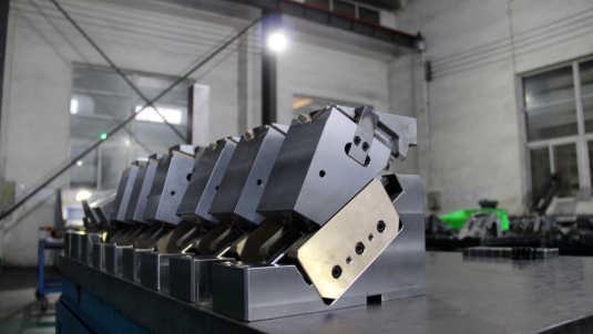
Essential Die Components and Their Functions
You've selected the right type of die for your application—but do you know what's actually inside that tooling? Understanding die components isn't just technical trivia. Each element directly influences performance, precision, and longevity. When suppliers quote you a price, the quality of these individual components often determines whether that die delivers consistent parts for 500,000 cycles or fails after 50,000.
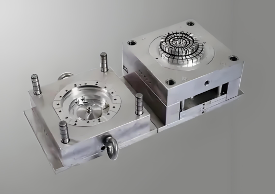
A manufacturing die is essentially a precision assembly of interconnected parts, each serving a specific purpose. Think of it like an engine: every component must work in harmony, and a weak link anywhere compromises the entire system. Let's examine the anatomy of a typical die set so you can evaluate die tooling with confidence.
Upper and Lower Die Assembly Structure
Every die tool starts with its foundation—the die shoes. Also called die plates or die sets, these thick steel or aluminum plates serve as mounting surfaces for all other components. The upper die shoe attaches to the press ram and moves vertically, while the lower die shoe remains fixed to the press plate or bolster.
According to Moeller Precision Tool, die plates hold punches, buttons, springs, and other critical elements in precise alignment. Material selection matters here—steel provides maximum rigidity for heavy-duty applications, while aluminum offers weight savings when press tool speed is a priority.
The quality of your die shoes directly impacts everything that follows. Warped or poorly machined plates introduce alignment errors that cascade through every operation. When evaluating a die press setup, examine the die shoes first—they reveal a lot about overall build quality.
Precision Alignment Components
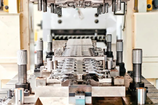
How do the upper and lower halves of a die maintain perfect alignment through millions of cycles? That's the job of guide pins and bushings—the unsung heroes of die tooling accuracy.
Guide pins are precision-ground cylindrical posts that extend from one die shoe and slide into matching bushings on the opposite shoe. As noted in industry specifications, these components are manufactured to tolerances within 0.0001 inches (one "tenth") to ensure exact positioning every time the die closes.
Two main types of guide pins exist:
- Friction (straight) guide pins – Slightly smaller than the bushing's inner diameter, providing accurate guidance but requiring more force to separate die halves
- Ball-bearing guide pins – Glide on a sequence of ball bearings within an aluminum cage, allowing smoother operation and easier die separation; these have become the industry standard due to their ease of use
Guide bushings, typically made from wear-resistant bronze alloys or coated materials, provide the sliding surface that mates with guide pins. According to HLC Metal Parts, these bushings reduce friction and increase mold life while maintaining guidance accuracy throughout extended production runs.
Spring devices installed on guide columns absorb impact forces during operation, protecting both the die and the punch and die set while providing sufficient reaction force to return components to their original positions.
Cutting and Forming Elements Explained
Now we reach the business end of the die—the punch and die components that actually transform your material. Understanding these elements helps you assess whether a quoted die design will deliver the precision your parts require.
Punches are the male cutting or forming elements, typically mounted in the upper die shoe. They press into the workpiece to cut holes, create shapes, or form bends. A die punch can have various nose shapes—round, oblong, square, rectangular, hex, or custom configurations—depending on the required feature geometry. High-speed tool steel, carbide, or other wear-resistant materials ensure punches withstand repeated high-intensity impacts.
Die buttons and cavities serve as the female counterparts to punches. They provide the cutting edge or forming cavity that receives the punch. The clearance between punch and button—called "die break"—typically runs 5-10% of material thickness, allowing proper shearing action to occur.
Here's a comprehensive breakdown of essential die components and their functions:
- Die shoes (upper/lower) – Foundation plates that mount and align all other components; made from steel or aluminum depending on application requirements
- Guide pins and bushings – Precision alignment system ensuring upper and lower dies meet accurately; manufactured to 0.0001" tolerances
- Punches – Male elements that press into material to cut or form features; available in various nose shapes and materials
- Die buttons/cavities – Female elements receiving punches; provide cutting edges or forming surfaces for material transformation
- Strippers – Hold workpieces in place during operations and remove material from punches after forming; can be mechanical or urethane-based
- Pilots – Precision pins that align material within the die during each operation; ensure workpieces stay correctly positioned for accurate cuts
- Die springs – Helical compression springs providing elastic support and restoring force; available as mechanical coil or nitrogen gas types
- Die retainers – Hold cutting and forming components in place; types include ball-lock, shoulder, trumpet head, and retractable designs
- Backup plates – Support die blocks and prevent deformation under high pressure; essential for maintaining dimensional accuracy
- Knockouts and ejectors – Remove finished parts from the die after stamping, preventing sticking and ensuring smooth operation
Strippers and pressure pads deserve special attention. These press tool components hold material flat during operations and strip it from punches afterward. Poor stripper design leads to part distortion and feeding problems—issues that multiply across high-volume production runs.
Pilots serve as positioning mechanisms, aligning material precisely within the die during each stroke. In progressive dies, pilots engage locating holes in the carrier strip to ensure every station operates on correctly positioned material. Misaligned pilots cause dimensional drift—a quality problem that may not appear until parts reach assembly.
The quality of these die components directly translates to manufacturing outcomes. Premium punches maintain sharper cutting edges longer, reducing burr formation and dimensional variation. Precision-ground bushings keep alignment consistent, preserving surface finish quality across extended production runs. When your supplier quotes a price, ask about component specifications—the answers reveal whether you're getting a die built for the long haul or one that will demand costly maintenance far sooner than expected.
Die Materials Selection for Optimal Performance
Here's a cost factor most suppliers gloss over: the material your manufacturing die is made from determines far more than just the initial price tag. Die steel selection directly influences tooling lifespan, maintenance frequency, part quality consistency, and ultimately, your per-unit production costs across thousands—or millions—of cycles.
Sounds complex? It doesn't have to be. The key is matching your die material to three critical variables: what you're stamping, how many parts you need, and how tight your tolerances must be. Get this equation right, and your tooling pays dividends for years. Get it wrong, and you're facing premature wear, unexpected downtime, and replacement costs that weren't in your original budget.
Tool Steel Grades for Different Applications
Die steel isn't a one-size-fits-all material. Different tool steel grades offer distinct balances of hardness, toughness, and wear resistance. According to the Alro Tool & Die Steel Handbook, tool steel refers to any alloy steel that's hardened and used in tooling applications, with modern grades offering significant improvements in size stability, wear resistance, and toughness over earlier formulations.
The most common steel die grades include:
- D2 (Air Hardening Die Steel) – Offers extremely high wear resistance with hardness reaching 60-62 HRC after heat treatment. D2 contains 11-13% chromium and excels in blanking, stamping, and cold forming dies. However, it has relatively low toughness (Charpy value around 32), making it less suitable for applications involving shock or impact.
- A2 (Air Hardening Die Steel) – Provides a good combination of wear resistance and toughness with hardness of 58-62 HRC. A2 is very stable in heat treatment and easier to machine and grind than D2, making it a versatile choice for general-purpose tooling dies.
- S7 (Shock Resisting Steel) – Delivers exceptional toughness (Charpy value around 75) combined with good wear resistance. S7 hardens to 54-58 HRC and is ideal for dies facing repetitive impact and mechanical shock. Its air-hardening capability also provides good size stability during heat treatment.
- H13 (Hot Work Die Steel) – Designed for elevated temperature applications, H13 maintains strength up to 600°C with hardness of 44-52 HRC. According to Neway Die Casting, H13 is the industry standard for aluminum and zinc die casting molds due to its excellent balance of strength, toughness, and heat resistance.
The differences between these grades matter more than many buyers realize. A metal die built from D2 might last three times longer than one made from softer materials when stamping abrasive high-strength steels—but that same D2 die could crack under impact loads where S7 would survive without issue.
When Carbide Makes Sense
For extreme wear resistance, tungsten carbide inserts take tooling dies to another level. With hardness exceeding 80 HRC—significantly harder than any steel die—carbide components resist abrasive wear that would destroy conventional tool steels in a fraction of the cycles.
Carbide makes sense for:
- High-wear punch tips in progressive dies running abrasive materials
- Trimming and shearing operations requiring extended edge life
- Long-run applications where consistent dimensional accuracy is critical
- Die formed components requiring millions of parts without significant wear
The tradeoff? Carbide is brittle. It handles compression beautifully but fractures under shock loads that tougher materials would absorb. This is why carbide typically appears as inserts within steel die bodies rather than as complete die structures. The forming dies surrounding carbide components provide the impact resistance the carbide itself lacks.
Bronze alloys—particularly beryllium copper—fill another specialized niche. With thermal conductivity up to 110 W/m·K (compared to approximately 24 W/m·K for H13), these materials excel in applications requiring rapid heat dissipation. Core pins, slides, and inserts benefit from bronze alloys when cooling efficiency or surface finish requirements drive design decisions.
Matching Materials to Production Demands
How do you choose the right material for your specific application? Consider these key selection factors:
Production Volume Requirements: Low-volume runs rarely justify premium die steel investments. P20 pre-hardened steel (28-32 HRC) offers excellent machinability and adequate performance for prototype molds and short-run tools. But push beyond 100,000 cycles, and you'll want harder materials. For runs exceeding 500,000 shots, H13 or carbide inserts become cost-effective investments.
Workpiece Material Hardness: Stamping mild steel creates far less tool wear than processing high-strength alloys or abrasive materials. When your incoming material has hardness approaching or exceeding 40 HRC, your tooling dies need proportionally harder cutting surfaces to maintain edge integrity.
Required Surface Finish: Some applications demand cosmetic-quality surfaces (Ra < 0.4 µm), while others accept rougher finishes. Materials like beryllium copper polish to mirror finishes more readily than high-chromium tool steels. Your surface requirements influence both material selection and post-machining processes.
Budget Constraints: Premium materials cost more upfront but often deliver lower total cost of ownership. A D2 die costing 30% more than an A2 alternative might last twice as long in abrasive applications, making it the economical choice despite higher initial investment.
| Material Type | Hardness Range (HRC) | Best For | Relative Cost |
|---|---|---|---|
| P20 (Pre-hardened) | 28-32 | Prototype molds, short-run tools, low-volume production | Low |
| A2 (Air Hardening) | 58-62 | General-purpose dies, forming tools, balanced wear/toughness needs | Medium |
| S7 (Shock Resisting) | 54-58 | Impact-intensive dies, trim dies, applications with mechanical shock | Medium |
| D2 (High Chrome) | 60-62 | High-wear cold work dies, blanking, stamping abrasive materials | Medium-High |
| H13 (Hot Work) | 44-52 | Aluminum/zinc die casting, hot extrusion, elevated temperature applications | Medium-High |
| Beryllium Copper | 35-45 | Core pins, slides, inserts requiring heat dissipation or fine finish | High |
| Tungsten Carbide | >80 | Extreme wear inserts, long-life shearing tools, high-volume precision parts | Very High |
Heat treatment transforms die bare steel into production-ready tooling. As noted by Qilu Steel Group, the primary heat treatment processes—annealing, quenching, and tempering—significantly influence mechanical properties. Proper control of these processes is essential to achieve desired performance characteristics.
Annealing softens material for easier machining prior to final hardening. Quenching rapidly cools heated steel to create maximum hardness through martensite formation. Tempering then reduces brittleness while maintaining necessary hardness levels. The specific temperatures and timing vary by grade—H13 typically tempers between 1000-1100°F for hot work applications, while D2 may use a "high double draw" at 950-975°F for maximum toughness.
The bottom line? Material selection isn't a place to cut corners. The difference between adequate and optimal die steel directly impacts how long your tooling lasts, how consistent your parts remain, and how much you'll spend on maintenance and replacement over the life of your production program. When evaluating quotes, ask specifically about die materials and heat treatment specifications—the answers reveal whether you're investing in tooling built for longevity or simply buying the cheapest option available.
The Die Manufacturing Process From Design to Production
You've selected your die type, understand the components involved, and specified the right materials. But what happens between placing an order and receiving production-ready tooling? The die process itself represents a significant cost driver—and one where hidden inefficiencies can inflate your budget without adding value.
What is die making at its core? It's a multi-stage precision manufacturing workflow that transforms engineering concepts into hardened steel tooling capable of producing millions of identical parts. Each step builds on the previous, and shortcuts anywhere in the sequence create problems that compound downstream. Understanding this process helps you evaluate suppliers, anticipate lead times, and identify where costs can be optimized without sacrificing quality.
Design and Engineering Phase
Every manufacturing die begins as a digital concept. This initial phase consumes significant engineering hours—and for good reason. Decisions made here determine whether your tooling works flawlessly or requires costly corrections later.
According to Walkson, the design and planning stage involves analyzing the part to be produced, its dimensions, tolerances, and material properties. Engineers use computer-aided design (CAD) software to create detailed models including the shape of the die cavity, draft angles, flash land, and other critical features.
The engineering workflow typically progresses through these critical activities:
- Requirements Analysis – Engineers examine your part specifications, production volume targets, material characteristics, and tolerance requirements to establish design parameters
- CAD Modeling – Detailed 3D models define every die component, including punch geometries, cavity profiles, guide systems, and stripper configurations
- CAE Simulation and Validation – Advanced finite element analysis (FEA) tools predict how material will flow within the die, identifying potential defects like splits, wrinkles, or springback before any metal is cut
- Material Selection – Based on production demands and workpiece characteristics, engineers specify appropriate die steels for each component
Here's where modern technology delivers substantial cost savings. As noted in the automotive die tryout procedure guide, virtual simulation allows engineers to predict and resolve potential issues digitally. Changing a feature in simulation might take an hour, whereas the equivalent physical change on a steel die could take a week. This shift from reactive problem-solving to proactive prevention dramatically reduces development time and eliminates expensive correction loops.
Think of CAE simulation as insurance against costly surprises. The software models everything from material flow to tool deflection and springback, allowing optimization before machining dies from expensive tool steel. Suppliers who skip this step may offer lower quotes initially—but those savings evaporate when physical tryout reveals problems that simulation would have caught.
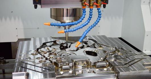
Precision Machining Operations
Once designs are validated, die machining transforms raw steel blocks into precision components. This stage represents significant cost and lead time, involving multiple specialized processes.
The machining sequence follows a logical progression:
- Material Preparation – Raw die steel is cut to approximate size using bandsaws or CNC cutting equipment, then undergoes initial heat treatment (annealing) to optimize machinability
- Rough Machining – Large cutting tools remove excess material to create basic shapes, leaving stock for precision finishing operations
- Precision CNC Machining – Computer-controlled milling, turning, and drilling operations create intricate details with tolerances measured in thousandths of an inch
- EDM Processing – Electrical discharge machining handles complex geometries that conventional cutting tools cannot achieve—sharp internal corners, deep narrow slots, and intricate contours become possible when a machine die component through controlled electrical erosion
- Heat Treatment – Hardening and tempering processes transform soft steel into wear-resistant tooling capable of withstanding millions of production cycles
- Precision Grinding – Final surface finishing achieves exact dimensional tolerances and surface quality specifications; according to Walkson, die surfaces are polished to ensure smooth material flow during operation and improve part surface finish
EDM deserves special attention because it enables geometries impossible through conventional machining. Wire EDM cuts complex profiles by passing a thin electrified wire through the workpiece, while sinker EDM uses shaped electrodes to create cavities matching desired forms. These processes add cost but prove essential for progressive dies with intricate punch profiles or forming dies requiring precise radii.
The die machine capabilities of your supplier directly impact what's achievable—and at what price. Shops with modern five-axis CNC equipment, precision EDM systems, and in-house heat treatment produce higher quality tooling faster than those relying on older technology or outsourced processes.
Assembly, Testing, and Validation
Machined components don't become functional tooling until they're assembled, tested, and proven capable of producing conforming parts. This final phase—often called die tryout—separates adequate suppliers from excellent ones.
The assembly and validation process includes:
- Component Assembly – Upper and lower die shoes, guide systems, punches, die buttons, strippers, and all supporting elements are fitted together with precision alignment
- Initial Press Setup – The assembled die is installed in a tryout press, and technicians establish baseline settings for tonnage, stroke, and cushion pressure
- First Article Production – Sample parts are stamped and immediately subjected to rigorous inspection using coordinate measuring machines (CMMs) or 3D laser scanners
- Die Spotting and Debugging – If discrepancies appear, technicians identify problem areas through die spotting—a technique involving colored paste that reveals where surfaces make non-uniform contact—then make targeted corrections
- Iterative Adjustment – Based on inspection results, toolmakers modify forming surfaces, adjust clearances, or shim components until parts meet specifications
- Final Validation – Once consistent quality is achieved, a final sample set is produced with comprehensive measurement documentation (Initial Sample Inspection Report) proving the die's capability
How to make a die that works right the first time? Virtual simulation during the design phase significantly reduces physical correction loops. According to industry case studies, difficult progressive dies might traditionally require five to eight tryout iterations. Advanced CAE simulation can cut that number in half, saving weeks of development time and substantial debugging costs.
The tryout phase reveals whether earlier design and machining decisions were correct. Suppliers who invest in simulation technology and skilled tryout technicians deliver production-ready tooling faster—with fewer surprises and change orders that inflate your final costs.
Understanding this complete die making workflow puts you in a stronger position when evaluating quotes. A supplier offering significantly lower prices may be cutting corners in simulation, using older machining technology, or allocating less time for proper tryout. These shortcuts create hidden costs that surface later as quality problems, extended lead times, or tooling that wears out prematurely. The next chapter addresses what happens after your die enters production—maintenance and lifecycle considerations that most suppliers never mention upfront.
Die Maintenance and Lifecycle Management
Your manufacturing die just arrived—engineered to perfection, validated through rigorous tryout, and ready for production. But here's what most suppliers won't tell you: the moment that tooling enters service, the clock starts ticking on its performance life. What is a die used for after delivery? Producing parts, certainly—but also accumulating wear that, left unmanaged, quietly degrades quality and inflates your costs.
Die maintenance isn't glamorous, but it's one of the most overlooked cost factors in manufacturing. According to The Phoenix Group, a poorly defined die shop management system can dramatically decrease press line productivity and increase costs. Poor maintenance causes quality defects during production, drives up sorting costs, increases the likelihood of shipping defective parts, and risks expensive containments.
Preventive Maintenance Best Practices
Think of preventive maintenance as insurance against catastrophic failures. A die is used to produce consistent parts cycle after cycle—but only when its cutting edges stay sharp, alignment remains true, and components operate within design tolerances.
Effective preventive maintenance programs include these essential practices:
- Regular inspection schedules – Establish routine checks based on production cycles rather than calendar time; high-volume dies may need inspection every 50,000 hits while lower-volume tools might run 200,000 cycles between reviews
- Lubrication requirements – Guide pins, bushings, and moving components require proper lubrication to prevent galling and premature wear; document lubricant types and application intervals
- Sharpening intervals – Cutting edges dull progressively; schedule resharpening before burrs exceed acceptable limits rather than waiting for visible quality problems
- Component replacement timing – Springs lose force, pilots wear undersize, and strippers degrade; track cycle counts and replace wear components proactively
- Cleaning protocols – Remove slugs, debris, and lubricant buildup that can cause misfeeds or surface contamination on finished parts
Data-driven maintenance outperforms guesswork. As noted by Gromax Precision, modern die equipment increasingly uses hit logs, coil counts, and predictive modeling to build maintenance schedules that are proactive rather than reactive. Monitoring tonnage trends can signal dull tooling or misalignment long before tolerances drift too far.
Recognizing Signs of Die Wear
Even with preventive programs in place, wear happens. The key is catching problems early—before they cascade into quality escapes or catastrophic die damage. Experienced die makers watch for these warning signs:
- Burr formation – Increasing burr height on cut edges indicates dull punches or excessive die clearance; when burrs exceed specification limits, sharpening is overdue
- Dimensional drift – Parts trending toward tolerance limits suggest component wear; AI-powered SPC tools can detect subtle trends earlier than manual inspection alone
- Surface degradation – Scratches, galling marks, or pickup on formed surfaces indicate die surface breakdown or inadequate lubrication
- Alignment issues – Uneven wear patterns, off-center holes, or inconsistent bend angles point to worn guide components or press alignment problems
- Increased tonnage requirements – A slow rise in press force often signals dull tooling or misalignment, providing critical maintenance clues
- Feeding problems – Misfeed rates climbing suggest worn pilots, degraded strippers, or timing issues within the die
The die industry increasingly relies on inline vision inspection and automated scanners to catch micro-level dimensional changes in real time. Spotting hole size creep, springback shifts, or feature rounding while still in production is faster and cheaper than waiting for end-of-line rejections.
When Repair vs Replacement Makes Sense
Eventually, every die faces a decision point: repair or replace? The answer depends on several factors that the die making industry weighs carefully.
Repair makes sense when:
- Wear is localized to replaceable components (punches, die buttons, springs)
- Core structure remains sound and properly aligned
- Repair costs stay below 40-50% of replacement value
- Production requirements haven't changed significantly
Replacement becomes necessary when:
- Die shoes show warping, cracking, or dimensional instability
- Multiple components require simultaneous attention
- Design changes necessitate significant modifications
- Cumulative repair costs approach replacement value
Expected service life varies dramatically based on production volume, material factors, and maintenance quality. A well-maintained progressive die running mild steel might deliver 2-3 million cycles before major refurbishment. The same tooling processing high-strength steel could require attention at 500,000 cycles. Carbide inserts extend wear life significantly but cannot prevent eventual component fatigue.
Creating a robust die shop management system—including prioritized work orders, skilled trade resources, and systematic decision trees—will decrease visible and invisible costs at the press line before they occur. The investment in proper lifecycle management pays dividends through extended die life, consistent part quality, and predictable production schedules. Understanding these maintenance realities positions you to budget accurately for total tooling ownership—not just the initial purchase price.
Cost Factors and Investment Considerations for Dies
Here's the uncomfortable truth about die for manufacturing procurement: the number on your supplier's quotation rarely tells the full story. Most buyers fixate on that initial price—and that's exactly where costly mistakes begin. According to Jeelix, equating a mold's purchase price with its total cost is one of the most common traps in manufacturing. The initial price is often just the tip of the iceberg, with massive, project-defining costs hidden beneath the surface.
Understanding what actually drives die costs—and how those costs translate into long-term value—separates strategic buyers from those who end up paying more for less. Let's break down the factors that determine whether your tooling investment delivers returns or drains your budget.
Key Factors That Influence Die Costs
When suppliers quote dies manufacturing projects, they're calculating costs across multiple interconnected variables. Some are obvious; others hide in plain sight. Here are the primary cost drivers you need to understand:
- Die complexity and number of operations – A simple blanking die costs a fraction of a progressive die with 15 stations. Each additional operation adds engineering time, more components, tighter tolerances, and extended tryout cycles. According to Die-Matic, part complexity is a major contributor to overall costs in precision metal stampings.
- Material selection – As covered earlier, D2 tool steel costs more than A2, and carbide inserts add significant expense. But cheaper materials often mean shorter tool life and more frequent replacements—a classic case where saving upfront costs more downstream.
- Tolerance requirements – Tighter tolerances demand precision grinding, more careful heat treatment, and extended inspection. Specifying ±0.001" when ±0.005" would suffice can inflate costs by 20-30% without adding functional value.
- Production volume expectations – Your anticipated run quantity determines appropriate die classification. A Class 104 die rated for 100,000 cycles costs far less than a Class 101 rated for 1,000,000+ cycles—but using the wrong class for your die application creates either wasted investment or premature failure.
- Lead time demands – Rush orders compress schedules, require overtime labor, and may necessitate premium material sourcing. Standard lead times typically deliver better value unless production deadlines absolutely require acceleration.
- Surface finish specifications – Mirror polishes requiring hundreds of hours of expert hand work dramatically exceed costs for standard machined finishes. Reserve premium finishes for surfaces that truly require them.
The relationship between these factors isn't linear—it's exponential. A complex geometry with tight tolerances in premium materials on a rush schedule doesn't just add costs; it multiplies them. Smart procurement requires evaluating which specifications genuinely add value versus which simply inflate quotes.
Calculating Return on Tooling Investment
Here's where the math gets interesting. Manufacturing tooling represents a significant upfront investment, but that investment amortizes across every part produced. The more parts you make, the lower your per-unit tooling cost becomes.
Consider Total Cost of Ownership (TCO) rather than purchase price alone. As noted by M&M Sales & Equipment, total cost of ownership goes far beyond improvement costs alone and includes direct and indirect costs as well. Your tools and equipment can have a significant impact on your operational costs over time.
TCO variables to factor into your ROI calculations include:
- Operating costs per cycle
- Cycle time and run time efficiency
- Scrap rate percentage
- Tool and die life expectancy
- Downtime for maintenance and repair
- Cost-per-part across full production volume
A real-world example illustrates this principle: one manufacturer invested in upgraded tooling that initially cost more than alternatives. The result? They shaved 1,000 production hours, saved $100,000 per batch, and gained improved customer stickiness with lower cost-per-runs while achieving better tool life and increased machine uptime.
When evaluating die sale opportunities or comparing quotes, calculate the per-part tooling cost by dividing total die investment by expected lifetime production. A $50,000 die producing 1,000,000 parts costs $0.05 per unit in tooling amortization. A $30,000 die that only lasts 300,000 cycles costs $0.10 per unit—nearly double—despite the lower sticker price.
Balancing Quality and Budget
The question isn't whether to spend more or less—it's where to allocate your investment for maximum return. Premium tooling justifies higher initial costs when:
- Production volumes exceed 500,000 parts over the program lifecycle
- Part quality requirements demand consistent dimensional accuracy
- Downtime costs significantly impact production schedules
- Material being stamped is abrasive or high-strength
- Surface finish requirements are critical to end-product function
Conversely, economical die in manufacturing approaches make sense for prototype runs, short-term programs, or applications where slight quality variations remain acceptable.
The strategic buyer approaches procurement with a framework that considers both immediate costs and lifecycle implications. According to Jeelix, the only true compass for strategic procurement is pursuing the lowest TCO, not the lowest sticker price. This requires decision-makers with the foresight to evaluate long-term value rather than reacting to initial quote comparisons.
Before finalizing any dies manufacturing purchase, map your cost factors against expected production requirements. Ask suppliers to justify material selections, explain tolerance impacts, and clarify how their pricing reflects anticipated die life. Those conversations reveal whether you're getting value-engineered tooling or simply the cheapest option available—two very different propositions when total ownership costs enter the equation.
Industry Applications and Die Selection Guidance
You've evaluated die types, materials, and cost factors—but here's where theory meets practice. Which tooling actually fits your specific industry? The answer isn't universal. A metal stamping die engineered for automotive body panels operates under completely different constraints than one producing electronic connectors or aerospace structural components.
Understanding industry-specific requirements helps you avoid a costly mismatch: buying tooling that's overengineered for your needs (wasting capital) or underspecified for your demands (creating quality failures). Let's examine how tool and die manufacturing requirements differ across major sectors and what that means for your supplier selection.
Automotive Stamping Die Requirements
The automotive sector represents the most demanding environment for metal stamping dies. Body panels, structural brackets, chassis components, and interior trim pieces all require tooling that delivers consistent quality across production volumes measured in millions.
What makes automotive tool and die requirements unique? According to Die-Matic, common applications include body panels and brackets in automotive, where precision is crucial and stamping delivers reliable, repeatable accuracy in every part. The stakes are high: a dimensional shift of just a few thousandths of an inch can cause assembly problems cascading through the entire vehicle build.
Key automotive die requirements include:
- Tight dimensional tolerances – Body panels must mate precisely with adjacent components; structural parts require exact fit for weld fixtures
- High surface finish quality – Exterior panels demand Class A surfaces free from visible defects after painting
- Extreme durability – Dies must maintain specification compliance across 500,000+ cycles without significant wear
- Multi-material capability – Advanced high-strength steels, aluminum alloys, and mixed-material constructions require tooling engineered for each substrate
Progressive die metal stamping dominates automotive production. As Wedge Products notes, progressive stamping is ideal for high-volume production of complex parts that demand both accuracy and repeatability—precisely what automotive manufacturing requires.
For manufacturers seeking automotive-focused dies and stamping solutions, Shaoyi represents the standard for precision stamping die manufacturing. Their IATF 16949 certification demonstrates compliance with automotive quality management requirements, while advanced CAE simulation capabilities prevent defects before physical production begins. With rapid prototyping available in as little as 5 days and a 93% first-pass approval rate, their engineering team delivers tooling that meets OEM standards without extended development cycles. Explore their comprehensive mold design and fabrication capabilities at their automotive stamping dies page.
Electronics and Precision Applications
Electronics manufacturing presents a different challenge: miniaturization combined with high-volume production. Connectors, terminal pins, lead frames, RF shielding housings, and heat sinks all require tooling capable of producing extremely small features with micron-level precision.
A die cutter for metal in electronics applications must handle:
- Micro-scale features – Contact pins and connector terminals measured in fractions of millimeters
- Thin materials – Copper alloys, phosphor bronze, and beryllium copper often under 0.5mm thickness
- High-speed operation – Production rates exceeding 1,000 strokes per minute for maximum throughput
- Consistent plating compatibility – Burr-free edges essential for subsequent gold, silver, or tin plating operations
Progressive dies excel in electronics because they combine multiple operations—blanking, forming, coining—into single-pass production. According to Wedge Products, this approach is ideal for creating small, detailed parts like connectors and terminals where precision manufacturing ensures uniformity and accuracy.
Heat sink production introduces thermal management considerations. Aluminum fin arrays require forming dies capable of creating thin, closely-spaced fins without tearing or distortion. Industrial die cutting machine setups for heat sinks often incorporate specialized lubricants and controlled atmospheres to prevent surface oxidation.
Appliance and Consumer Products
Appliance manufacturing balances cost efficiency with aesthetic requirements. Enclosures, internal brackets, motor housings, and cosmetic trim components each present distinct tooling challenges.
Typical appliance die applications include:
- Large enclosures – Refrigerator liners, washing machine drums, and oven cavities requiring deep draw capability
- Structural frames – Load-bearing brackets and chassis components where strength matters more than surface finish
- Cosmetic panels – Control panels, door faces, and trim pieces requiring consistent appearance
- Internal components – Motor brackets, wire guides, and mounting plates with functional but non-cosmetic requirements
Transfer dies often serve appliance production well, particularly for larger components requiring multiple forming operations that progressive tooling cannot accommodate. The ability to move parts between stations allows complex geometries impossible in single-stroke operations.
Aerospace and Defense Applications
Aerospace manufacturing demands the highest precision combined with complete traceability. Structural components, fastener hardware, and aircraft skin panels must meet exacting specifications—with documentation proving every part's conformance.
Die casting in automotive industry applications shares some characteristics with aerospace stamping, but aerospace adds layers of complexity:
- Exotic materials – Titanium alloys, Inconel, and aerospace-grade aluminum require specialized die materials and coatings
- Absolute traceability – Every component must link to specific material lots, die maintenance records, and inspection data
- Zero-defect requirements – Flight-critical components cannot tolerate the statistical process variation acceptable in other industries
- Certification compliance – AS9100 and Nadcap certifications verify supplier capability for aerospace production
Compound dies find extensive use in aerospace for flat precision parts requiring simultaneous blanking and piercing. The single-stroke operation minimizes dimensional variation that could accumulate across multiple operations.
Industry-Specific Quality Standards
Your industry determines which certifications matter when selecting die manufacturers. These aren't just paperwork—they represent systematic approaches to quality that directly impact the tooling you receive.
| Industry | Key Certifications | Die Characteristics Required | Typical Die Types |
|---|---|---|---|
| Automotive | IATF 16949, ISO 9001 | High durability, tight tolerances, Class A surface capability | Progressive, Transfer |
| Electronics | ISO 9001, IPC standards | Micro-precision, high-speed operation, burr-free cutting | Progressive, Compound |
| Appliance | ISO 9001 | Deep draw capability, cost efficiency, moderate tolerances | Transfer, Progressive |
| Aerospace | AS9100, Nadcap | Exotic material capability, complete traceability, zero-defect | Compound, Progressive |
| Medical | ISO 13485, FDA compliance | Biocompatible finishes, validation documentation, cleanroom compatibility | Progressive, Compound |
For automotive applications specifically, IATF 16949 certification represents the gold standard. This globally recognized quality management standard requires suppliers to maintain robust quality management systems, implement comprehensive risk analysis, and demonstrate continuous improvement. According to Smithers, organizations adhering to this standard reap benefits including improved customer satisfaction, enhanced consistency of operations, and better risk management.
IATF 16949 requirements specifically demand:
- Process-oriented approach for all business activities
- Robust product design and development processes
- Continuous monitoring and measurement of QMS effectiveness
- Evidence-based decision-making throughout production
When evaluating tools and dies suppliers, verify their certifications align with your industry requirements. A die manufacturer certified to automotive standards brings systematic quality approaches that benefit any precision application—even if you're not in the automotive sector. That certification signals investment in processes, equipment, and personnel capable of meeting demanding specifications consistently.
The intersection of industry requirements and die selection determines whether your tooling investment succeeds or struggles. Match your application demands to appropriate die types, verify supplier certifications relevant to your sector, and ensure engineering capabilities align with your production complexity. These considerations set the stage for evaluating potential manufacturing partners—which brings us to the criteria that separate exceptional die suppliers from adequate ones.
Choosing the Right Die Manufacturing Partner
You've analyzed die types, materials, processes, and industry requirements. Now comes the decision that ties everything together: selecting a manufacturing partner who can actually deliver. What is tool & die excellence in practice? It's not just about machining capability—it's about finding a supplier whose engineering depth, quality systems, and collaborative approach align with your production goals.
Choosing the wrong die manufacturer costs far more than the price difference between quotes. Extended lead times, quality escapes, design iterations, and production delays compound into expenses that dwarf any initial savings. According to Eigen Engineering, the profitability of your business could hinge on this decision. Ensure you're considering all angles and variables when selecting a stamping dies manufacturer.
Technical Capability Assessment
Before evaluating quotes, verify that potential die manufacturers actually possess the equipment and expertise your project demands. Not all tool and die shops are created equal—and capability gaps surface at the worst possible times.
Key technical capabilities to evaluate include:
- CNC machining capacity – Modern five-axis equipment produces complex geometries faster and more accurately than older three-axis machines; ask about spindle speeds, work envelope sizes, and tolerance capabilities
- EDM technology – Wire and sinker EDM systems handle intricate features conventional machining cannot achieve; verify equipment age and precision specifications
- Heat treatment capabilities – In-house heat treatment ensures tighter process control than outsourced operations; ask about furnace types and temperature monitoring systems
- Precision grinding – Surface grinders and jig grinders deliver final tolerances and surface finishes; confirm achievable specifications match your requirements
- In-house tryout presses – According to Ultra Tool Manufacturing, in-house stamping presses provide the ability to easily test tooling dies before full production begins—saving valuable time and money compared to shipping dies back and forth
Beyond equipment lists, assess depth of expertise. As Eigen Engineering notes, when a manufacturer advertises only one kind of service, it can be a red flag because their capabilities are limited. Having a partner that can offer tooling, assembly, die and tooling maintenance, and other services helps reduce steps in your supply chain and increases efficiencies.
Request examples of projects similar to yours. Go see their tool building services in action to better understand the equipment and their expertise. A facility visit reveals more about actual capability than any brochure.
Quality Certifications That Matter
Certifications aren't just wall decorations—they represent systematic approaches to quality that directly impact your tooling outcomes. For industrial tool die and engineering partnerships, verify credentials that align with your industry requirements.
Essential certifications to verify:
- ISO 9001:2015 – The baseline quality management standard; confirms documented processes and continuous improvement systems
- IATF 16949 – Automotive-specific quality management; demonstrates capability for the most demanding precision applications
- AS9100 – Aerospace quality standard for suppliers serving aviation and defense markets
- ISO 13485 – Medical device quality management for tooling serving healthcare applications
According to Eigen Engineering, regulatory agency and other ratings should be checked when you perform initial research on die manufacturers. Digital resources provide legal and compliance history that reveals past performance issues you'd otherwise miss.
Shaoyi exemplifies how certification translates into manufacturing excellence. Their IATF 16949 certification ensures automotive-grade quality management across all die manufacturing operations. Combined with comprehensive engineering capabilities and proven production processes, this systematic quality approach delivers the consistency demanding applications require. Explore their certification credentials and capabilities at their automotive stamping dies page.
Engineering Partnership Value
The difference between a die manufacturer and a true engineering partner lies in what happens before metal gets cut. Superior tools and dies suppliers invest in simulation, prototyping, and collaborative design—capabilities that prevent problems rather than just fixing them.
CAE simulation for defect prevention: According to Scan2CAD, the significance of computer-aided design (CAD) and computer-aided engineering (CAE) software in creating, verifying, and validating designs cannot be downplayed. Advanced simulation predicts material flow, springback, and potential defects before any steel is machined. Changing a feature in simulation takes hours; the equivalent physical change on hardened tooling takes weeks and thousands of dollars.
Shaoyi's engineering team leverages advanced CAE simulation to deliver defect-free results, identifying and resolving forming issues digitally before physical production begins. This proactive approach contributes to their 93% first-pass approval rate—a benchmark worth noting when evaluating potential suppliers.
Rapid prototyping acceleration: As noted by Scan2CAD, rapid prototyping significantly saves production time and cuts costs compared to conventional manufacturing. Prototypes can be delivered to clients to assess reception and seek feedback on design improvements before committing to full production tooling.
Speed matters. Shaoyi offers rapid prototyping in as little as 5 days, enabling faster design validation and accelerated time-to-market. When production schedules are tight, prototyping speed becomes a competitive advantage.
Production scalability: As Eigen Engineering emphasizes, you would not want to chain yourself with a manufacturer who cannot keep pace with in-demand and successful products. Ensure potential partners have the capacity to scale up production themselves, with fluid and proactive resources and production management capabilities.
Supplier Evaluation Checklist
Before finalizing your die manufacturer selection, work through this comprehensive evaluation framework:
-
Technical Capabilities
- CNC machining equipment (age, precision, capacity)
- EDM systems (wire and sinker capabilities)
- In-house heat treatment and grinding
- Tryout press availability and tonnage range
-
Quality Systems
- Relevant industry certifications (ISO, IATF, AS9100)
- Inspection equipment (CMM, optical comparators, surface finish gauges)
- Documentation and traceability processes
- Audit and compliance history
-
Engineering Support
- CAE simulation capabilities and software platforms
- Design for manufacturability consultation
- Rapid prototyping speed and options
- First-pass approval rates and revision history
-
Production Capacity
- Current utilization and available capacity
- Scalability for volume increases
- Die maintenance and repair services
- Secondary operations (assembly, inspection, packaging)
-
Partnership Factors
- Communication responsiveness and clarity
- Project management approach and touch points
- References from similar applications
- Geographic proximity and logistics considerations
According to Eigen Engineering, the perfect die manufacturer maintains honest processes, sets up sufficient touch points, and adheres to all your written manufacturing requirements. They are proactive and clear about any disruptions in the supply chain or changes therein. Ensure all expectations are in written documentation for all parties to reference.
Set up visits with representatives from each manufacturer you're considering. Explain all your products, desired services, and manufacturing expectations. After they explain their side, schedule a follow-up on-site visit. This helps you get the full professional scope, feel, and functionality of each facility.
Finally, consider total value rather than lowest price. As noted in our cost analysis chapter, comparing natural costs—shipping, tariffs, compliance, contract fees, and beyond—ensures you're evaluating true cost of ownership. Come up with ratings for primary services while noting impressions and additional vendor details.
For manufacturers seeking a qualified automotive stamping die partner with proven engineering capabilities, Shaoyi delivers the combination of advanced CAE simulation, rapid prototyping, IATF 16949 certification, and high-volume manufacturing capacity that demanding applications require. Their cost-effective tooling solutions meet OEM standards while maintaining the 93% first-pass approval rate that minimizes development cycles. Learn more about their comprehensive capabilities at https://www.shao-yi.com/automotive-stamping-dies/.
Selecting the right die manufacturing partner isn't just a procurement decision—it's a strategic choice that influences your production quality, timeline, and total cost of ownership for years to come. Use these evaluation criteria to identify suppliers whose capabilities, quality systems, and collaborative approach align with your manufacturing goals. The investment in thorough supplier assessment pays dividends through tooling that performs as specified, arrives on schedule, and delivers consistent results across your entire production program.
Frequently Asked Questions About Manufacturing Dies
1. What is a die in a factory?
A manufacturing die is a specialized tool designed to cut, shape, or form materials into precise configurations during mass production. Working with a press, dies transform raw materials like metal sheets, plastics, and rubber into finished components with consistent accuracy. Unlike simple cutting tools, dies can perform multiple operations simultaneously—cutting, bending, drawing, and forming—all in a single press stroke, making them essential for producing millions of identical parts with tolerances measured in thousandths of an inch.
2. What's the difference between tool and die?
Tools perform specific actions like cutting, bending, or punching materials, while dies are a specialized subset of tools designed to shape or form materials with high accuracy for repeated production. All dies are tools, but not all tools are dies. Dies are purpose-built for specific parts and work with presses to create precise, repeatable forms. Tool and die manufacturing encompasses both categories, with dies specifically focused on stamping, forming, and cutting operations in mass production environments.
3. How long does a manufacturing die last?
Die lifespan varies dramatically based on production volume, workpiece material, and maintenance quality. A well-maintained progressive die running mild steel can deliver 2-3 million cycles before major refurbishment, while the same tooling processing high-strength steel might require attention at 500,000 cycles. Carbide inserts extend wear life significantly. Proper preventive maintenance—including regular inspections, lubrication, sharpening intervals, and component replacement—directly extends die service life and maintains consistent part quality.
4. What factors affect manufacturing die costs?
Key die cost drivers include complexity and number of operations, material selection (D2, A2, S7, H13 tool steels or carbide), tolerance requirements, production volume expectations, lead time demands, and surface finish specifications. A progressive die with 15 stations costs significantly more than a simple blanking die. However, total cost of ownership matters more than purchase price—a $50,000 die producing 1,000,000 parts costs less per unit than a $30,000 die lasting only 300,000 cycles.
5. Why is IATF 16949 certification important for die manufacturers?
IATF 16949 certification represents the automotive industry's gold standard for quality management, requiring suppliers to maintain robust quality systems, implement comprehensive risk analysis, and demonstrate continuous improvement. Certified manufacturers like Shaoyi deliver systematic quality approaches including process-oriented operations, robust product development, continuous monitoring, and evidence-based decision-making. This certification signals investment in processes, equipment, and personnel capable of meeting demanding specifications consistently—benefiting any precision application.