 Small batches, high standards. Our rapid prototyping service makes validation faster and easier —

Machinist Parts Decoded: From Raw Material To Precision Component
What Are Machinist Parts and Why They Matter
When you hear the term "machinist parts," what comes to mind? If you're picturing both the custom components that roll off a CNC lathe and the machine tool parts that keep shop equipment running, you're not alone. This common ambiguity trips up engineers, procurement specialists, and hobbyists alike. Let's clear the air right from the start.
Defining Machinist Parts in Modern Manufacturing
In the manufacturing world, machinist parts primarily refer to custom-machined components produced in machine shops to meet specific application requirements. These aren't off-the-shelf items you grab from a catalog. Instead, they're precision components tailored to exact specifications - whether that's a shaft for an aerospace turbine or a specialized bracket for industrial machinery.
According to industry definitions, custom machined parts are components specifically designed and manufactured to meet unique requirements, typically using precision machining processes like CNC milling, turning, drilling, and EDM. These parts serve industries where standard components simply won't cut it - aerospace, automotive, medical, oil and gas, and manufacturing equipment sectors rely on them daily.
The Distinction Between Made Parts and Machine Components
Here's where things get interesting. The term "machinist parts" can actually mean two different things:
- Custom-machined components: Parts produced by machinists for end-use applications (the focus of this article)
- Tools for machinist work: The machinist tools, equipment, and machine shop tools used in the production process itself
Throughout this guide, we'll concentrate on the first category - the precision components that machinists create. Think shafts, bushings, spacers, brackets, fixtures, and jigs. These represent the bread and butter of what machine shops produce day in and day out.
Why does understanding this distinction matter? Imagine you're sourcing components for a prototype engine. Knowing whether you need to search for machinist equipment suppliers or custom part manufacturers can save you hours of misdirected effort. For engineers specifying parts, procurement specialists requesting quotes, or hobbyists tackling personal projects, this clarity is essential.
The journey ahead will take you through material selection, tolerance specifications, machining processes, and quality control methods. You'll gain practical knowledge that transforms how you approach custom component procurement - moving from uncertainty to confidence. No catalog listings here, just actionable insights you can apply immediately to your next project.
Categories of Machinist Parts by Function
Ever tried finding a specific component in a machine shop catalog organized alphabetically? Frustrating, right? When you need a part that supports another component under load, searching under "B" for bracket while overlooking "P" for plate wastes valuable time. A functional approach makes far more sense - organizing custom-machined components by what they actually do in your application.
This categorization system helps you quickly identify exactly which type of part solves your specific engineering challenge. Whether you're replacing a worn component or designing something new, understanding these functional categories streamlines your selection process considerably.
Structural Components and Load-Bearing Parts
Structural parts form the backbone of mechanical assemblies. These components bear loads, maintain rigidity, and provide mounting surfaces for other elements. When you need something that holds everything together under stress, you're looking at this category.
- Brackets: L-shaped or angular supports that mount components to frames or walls - commonly used in automotive suspension systems and industrial equipment mounting
- Plates: Flat, precision-ground surfaces that serve as mounting bases or structural reinforcement - essential in machine tool beds and assembly jigs
- Frames: Skeletal structures that define equipment geometry and distribute loads - found in everything from robotic arms to production machinery
- Gussets: Triangular reinforcement pieces that strengthen corner joints - critical in aerospace structures and heavy equipment fabrication
These components typically require tight flatness tolerances and consistent material properties throughout. Engineers often specify heat-treated steel or aircraft-grade aluminum depending on the strength-to-weight requirements of the application.
Fastening Components for Secure Connections
Standard bolts from a hardware store won't always cut it. Custom fastening components deliver precise fits, specialized materials, or unique geometries that off-the-shelf options simply can't provide. Think about it - when you're securing components in a high-vibration environment or need corrosion-resistant connections, custom fasteners become essential.
- Custom bolts and studs: Threaded fasteners machined to non-standard lengths, thread pitches, or head configurations - used in specialized equipment where standard sizes don't fit
- Dowel pins: Precision cylindrical pins that align mating parts with high accuracy - crucial for die sets, fixtures, and repeatable assembly operations
- Locating pins: Tapered or stepped pins that position components during assembly - found in automotive tooling and production fixtures
- Custom nuts and inserts: Threaded components designed for specific material thicknesses or load requirements - common in composite assemblies and thin-wall structures
A tap wrench might help you create threads manually for one-off prototypes, but production fastening components demand the precision only CNC equipment delivers.
Motion Control and Precision Elements
When something needs to rotate, slide, or move with precision, motion control components make it happen. These parts demand the tightest tolerances and finest surface finishes of any category - even microscopic imperfections can cause binding, wear, or failure.
- Shafts: Cylindrical components that transmit rotational motion and torque - the heart of motors, pumps, and power transmission systems
- Bushings: Cylindrical sleeves that provide bearing surfaces and reduce friction between moving parts - essential in pivot points and guide mechanisms
- Bearing housings: Precision-bored enclosures that support and align bearings - critical for maintaining proper shaft alignment in rotating machinery
- Lead screws and ball nuts: Threaded components that convert rotational motion to linear motion - fundamental to CNC machines and positioning systems
Lathe tools excel at producing these cylindrical components, with collets providing the grip needed to hold round stock securely during turning operations. Many machine shops keep various collet sizes on hand specifically for shaft and bushing production.
Sealing and Spacing Parts
Sometimes you need to fill a gap, create separation, or prevent leakage. Sealing and spacing components might seem simple, but they're surprisingly critical to system performance. A spacer that's a few thousandths off can throw an entire assembly out of alignment.
- Spacers: Cylindrical or tubular components that maintain precise distances between parts - used in bolt stacks, bearing assemblies, and optical equipment
- Shims: Thin, flat pieces that fill gaps and adjust alignment - essential for machine tool setup and precision assembly work
- Custom gaskets: Sealing components machined from specialized materials - required where standard gasket shapes won't conform to unique flange geometries
- Wear plates: Sacrificial surfaces that protect more expensive components from abrasion - common in material handling and processing equipment
Workholding Fixtures and Tooling
Before you can make precision parts, you need to hold the workpiece securely. Workholding components grip, position, and stabilize materials during machining operations. Without proper fixturing, even the best CNC equipment can't deliver consistent results.
- Jigs: Devices that guide cutting tools while holding the workpiece - used for repetitive drilling, boring, and machining operations
- Fixtures: Custom workholding devices that locate and clamp parts during machining - essential for complex multi-operation parts
- Clamps: Adjustable gripping devices that secure workpieces to machine tables - from simple strap clamps to sophisticated hydraulic systems
- Soft jaws: Custom-machined chuck jaws shaped to grip specific part geometries - critical for holding irregular or finished surfaces without damage
T-nuts slide into machine table slots to anchor clamps and fixtures, while a drill chuck mounted in a tailstock enables precise hole-making operations on lathe-mounted workpieces. Even an open ended wrench becomes essential tooling when you're adjusting fixture bolts in tight spaces.
Why Functional Organization Matters
This functional categorization transforms how you approach component selection. Instead of guessing at part names, you start with the problem: "I need something that bears a load," or "I need to control motion between these two points." The category leads you directly to the right type of component.
For procurement specialists, this framework simplifies communication with machine shops. Rather than describing a mysterious widget, you can specify "a motion control bushing with these dimensional requirements." Engineers benefit from understanding which category their design needs fall into, making it easier to specify appropriate materials and tolerances for each functional role.
With these categories in mind, the next step is understanding what materials best serve each function - a decision that significantly impacts both performance and cost.
Material Selection for Custom Machined Components
You've identified the type of part you need. Now comes a decision that will impact everything from manufacturing cost to long-term performance: material selection. Choose wisely, and your component delivers years of reliable service. Choose poorly, and you're looking at premature failure, excessive machining costs, or a part that simply can't hold the tolerances your application demands.
Material selection isn't just about picking the strongest or cheapest option. It's about matching properties to application requirements while keeping an eye on machinability - because what looks great on paper might be a nightmare to actually produce on a metal lathe or milling machine.
Matching Materials to Application Requirements
Before diving into specific materials, consider what your application actually demands. Ask yourself these questions:
- What loads will the part experience - static, dynamic, or cyclic?
- Will it encounter corrosive environments, moisture, or chemicals?
- What temperature range must it withstand during operation?
- Does weight matter for your application?
- Are there electrical conductivity or insulation requirements?
- What surface finish and tolerances does your design require?
Your answers narrow the field considerably. A bracket operating in a salt-spray marine environment needs very different material properties than a precision bushing running in a climate-controlled factory. Let's examine the primary material families and what they bring to the table.
Aluminum Alloys: The Workhorse of Custom Machining
Aluminum dominates modern CNC machining for good reason. According to Gardner's 2024 survey, 38% of all CNC-machined parts use aluminum. This lightweight metal offers an excellent strength-to-weight ratio at roughly one-third the density of steel.
Common aluminum grades include:
- 6061: The most common general-purpose alloy with good strength, excellent machinability, and cost efficiency - your go-to for prototypes and general applications
- 7075: Aircraft-grade aluminum with exceptional fatigue properties; can be heat-treated to compete with steel hardness
- 5083: Marine-grade with superior seawater resistance - ideal for boat components and coastal installations
Aluminum machines quickly and cleanly, reducing cycle times compared to harder materials. It can be anodized to create a hard, protective surface layer that enhances both wear resistance and corrosion protection. When you're cutting stock on a metal band saw before loading it into the machine, aluminum's soft nature makes preparation straightforward.
Steel Grades: When Strength Matters Most
Steel remains essential when high strength, hardness, or wear resistance are non-negotiable. The carbon content largely determines properties - higher carbon increases hardness but reduces weldability.
Mild steels (low carbon) like 1018 offer excellent machinability and weldability at lower cost. They're perfect for jigs, fixtures, and structural components that don't require extreme hardness. However, they're susceptible to corrosion without protective coatings.
Alloy steels such as 4140 and 4340 add chromium, molybdenum, or nickel for improved strength and toughness. These grades can be heat-treated to achieve specific hardness levels, making them suitable for gears, shafts, and high-stress components.
Tool steels like D2, A2, and O1 deliver exceptional hardness (up to 65 HRC) and wear resistance. They're the material of choice for dies, cutting tools, and components that must resist abrasion. Expect longer machining times and higher tool wear when working with these grades.
Stainless Steel: Corrosion Resistance Built In
When your parts will encounter moisture, chemicals, or food products, stainless steel's 10.5%+ chromium content provides inherent corrosion resistance. The material maintains strength from cryogenic temperatures up to 870°C.
- 304: The most common grade with excellent corrosion resistance and good machinability - suitable for most industrial and commercial applications
- 316: Higher nickel and molybdenum content for superior resistance to saltwater and chlorides - the choice for marine and chemical processing
- 303: Enhanced machinability through added sulfur; ideal for high-volume production of nuts, bolts, and fittings
- 17-4 PH: Precipitation-hardening grade that can match tool steel hardness while maintaining corrosion resistance
Stainless steel takes significantly longer to machine than aluminum. Production data shows that identical parts require 12 minutes in aluminum 6061 versus 28 minutes in stainless 316 - more than double the cycle time.
Brass: Low Friction and Excellent Machinability
Brass alloys combine copper and zinc to create materials with natural antimicrobial properties and outstanding machinability. C36000 (free-cutting brass) ranks among the easiest materials to machine, making it economical for high-volume production despite moderate raw material costs.
Applications include electrical connectors, decorative hardware, valve components, and any application requiring low friction. Brass also produces attractive gold-toned finishes without additional surface treatment.
Engineering Plastics: Beyond Metal Solutions
Don't overlook plastics when metal seems like the obvious choice. Engineering thermoplastics offer chemical resistance, electrical insulation, and significant weight savings. One medical device manufacturer saved 52% by switching from aluminum to polycarbonate housings without compromising specifications.
- Delrin (POM): Highest machinability among plastics with excellent dimensional stability; holds tolerances of ±0.05 mm over 100,000+ cycles
- Nylon: Good impact strength and chemical resistance; oil-impregnated grades provide self-lubrication
- PEEK: High-performance polymer suitable for continuous operation at 260°C; aerospace-qualified and biocompatible
- Polycarbonate: Impact strength 200 times greater than glass with optical clarity; maintains properties from -40°C to 120°C
Cost vs Performance Trade-offs in Material Selection
Every material choice involves trade-offs. The table below compares common CNC materials across key properties to help you balance performance requirements against budget constraints.
| Material | Machinability Rating | Tensile Strength | Corrosion Resistance | Relative Cost | Typical Applications |
|---|---|---|---|---|---|
| Aluminum 6061 | Excellent | Moderate (276 MPa) | Good | Low (baseline) | Prototypes, brackets, housings |
| Aluminum 7075 | Good | High (503 MPa) | Good | 1.4x baseline | Aerospace, high-stress components |
| Mild Steel 1018 | Good | High (370 MPa) | Poor | 0.8x baseline | Fixtures, structural parts |
| Stainless 304 | Moderate | High (215 MPa yield) | Excellent | 2.5x baseline | Food equipment, medical devices |
| Stainless 316 | Moderate | High (205 MPa yield) | Superior | 3x baseline | Marine, chemical processing |
| Brass C36000 | Excellent | Moderate (310 MPa) | Good | 2x baseline | Fittings, electrical connectors |
| Delrin (POM) | Excellent | Low (70 MPa) | Excellent | 1.2x baseline | Gears, bushings, precision parts |
| PEEK | Good | Moderate (100 MPa) | Excellent | 15x baseline | Aerospace, medical implants |
How Material Choice Affects Tolerances and Surface Finish
Here's something many engineers overlook: your material selection directly impacts what tolerances and surface finishes are practically achievable. Harder materials cause more tool deflection and wear, potentially limiting precision. Softer materials may deform under cutting pressure, creating dimensional inconsistencies.
Aluminum's excellent machinability allows shops to hold tighter tolerances economically - the material cuts cleanly without excessive tool wear or heat buildup. When operators need to verify dimensions using fraction to decimal conversion charts, aluminum parts consistently measure closer to nominal.
Stainless steel and titanium require slower cutting speeds and generate more heat, which can cause thermal expansion during machining. Achieving the same tolerance in stainless might require additional finishing passes with a grinding wheel or grinder wheel operations that add cost and time.
Plastics present their own challenges. While they machine easily, some grades absorb moisture and change dimensions. Others have high thermal expansion coefficients, meaning room temperature affects final size. Shim stock made from precision-ground plastics must account for these material behaviors.
Surface finish capability also varies by material. Brass and aluminum accept mirror-like finishes with minimal effort. Tool steels can achieve excellent finishes but require proper tooling and technique. Some plastics tend to leave fuzzy edges that need secondary deburring operations.
The right material isn't always the strongest or cheapest - it's the one that meets your functional requirements while remaining practical to machine within your tolerance and budget constraints.
With your material selected, the next critical step is understanding how to specify tolerances correctly. Getting this wrong can mean parts that don't fit, function poorly, or cost far more than necessary to produce.
Tolerances and Specifications Explained
You've selected your material and identified the type of component you need. Now comes the specification that separates functional parts from expensive scrap: tolerances. This is where many engineers, procurement specialists, and hobbyists stumble - either over-specifying requirements that balloon costs or under-specifying and ending up with parts that don't fit.
Here's the reality: that ±0.001" tolerance you just specified might have doubled your part cost and tripled your lead time. Understanding when precision matters versus when it's overkill can transform both your budget and your manufacturing relationships.
Understanding Tolerance Classes and Their Applications
Tolerances define the permissible limits of variation in a physical dimension, ensuring that features of machinist parts are produced within acceptable limits for their intended application. According to ISO standards widely used across manufacturing, tolerances fall into distinct classes that reflect both capability and cost.
Think of tolerance classes as tiers of precision. Each tier requires progressively more sophisticated equipment, environmental controls, and inspection protocols. The relationship between tolerance and manufacturing complexity isn't linear - it's exponential.
| Tolerance Class | Typical Range (Imperial) | Typical Range (Metric) | Relative Cost Multiplier | Typical Applications |
|---|---|---|---|---|
| Commercial/Standard | ±0.010" (±0.254mm) | ±0.25mm | 1x (baseline) | Brackets, covers, non-critical structural parts |
| Precision | ±0.005" (±0.127mm) | ±0.13mm | 1.5-2x | Bearing housings, mating surfaces, moderate-fit assemblies |
| High-Precision | ±0.001" (±0.025mm) | ±0.025mm | 3-4x | Precision shafts, close-tolerance bores, instrument components |
| Ultra-Precision | ±0.0001" (±0.0025mm) | ±0.003mm | 10-24x | Optical components, aerospace interfaces, metrology equipment |
Standard CNC machining processes typically achieve ±0.005" (±0.13mm) tolerances efficiently without special procedures. Manufacturing data shows that tightening to ±0.001" might require precision equipment, temperature-controlled environments, and specialized inspection routines that significantly increase costs.
When you're reviewing a fraction chart or decimal chart to interpret drawing dimensions, keep these tolerance classes in mind. A fraction decimal chart helps convert between formats, but the tolerance specification determines whether that dimension truly matters for function.
When Tight Tolerances Actually Matter
Here's the question experienced engineers ask: does this dimension actually need tight control? Most tolerance problems stem from poor allocation across assemblies rather than genuinely demanding applications. Consider these scenarios where precision truly matters:
- Interference fits: When a shaft must press into a bore with specific retention force
- Bearing interfaces: Where shaft roundness and size directly affect bearing life and performance
- Sealing surfaces: Flatness requirements that ensure gasket compression across the entire perimeter
- Motion control: Lead screws and linear guides where cumulative error affects positioning accuracy
- Assembly interchangeability: High-volume production where parts must assemble without fitting or adjustment
For non-critical dimensions - clearance holes, material removal features, or aesthetic surfaces - commercial tolerances often suffice. The goal is creating a tolerance hierarchy that focuses manufacturing resources where they deliver functional value.
Surface Finish Specifications and Their Practical Implications
Surface finish, measured as Ra (arithmetic average roughness) in microinches (µin) or micrometers (µm), describes how smooth a machined surface actually is. This specification directly affects friction, wear, sealing capability, and appearance.
| Ra Value (µin) | Ra Value (µm) | Surface Description | Typical Process | Common Applications |
|---|---|---|---|---|
| 250 | 6.3 | Rough machined | Sawing, rough turning | Non-contact surfaces, rough castings |
| 125 | 3.2 | Standard machined | Milling, turning | General purpose, most machinist parts |
| 63 | 1.6 | Fine machined | Finish milling, precision turning | Bearing surfaces, sealing faces |
| 32 | 0.8 | Ground finish | Grinding | Shafts, precision bores, sliding surfaces |
| 16 | 0.4 | Polished | Lapping, polishing | Sealing surfaces, optical mounts |
Smoother surfaces generally reduce friction and improve sealing - but they cost more to produce. Interestingly, very smooth finishes can actually hinder adhesion for coatings or gasket applications. Match your finish requirement to actual function rather than specifying mirror finishes everywhere.
GD&T Basics for Interpreting Engineering Drawings
Geometric Dimensioning and Tolerancing (GD&T) provides control beyond simple size tolerances. While linear tolerances address how big or small a feature can be, GD&T controls geometric relationships - flatness, perpendicularity, position, and more.
According to ASME Y14.5 standards, GD&T symbols fall into four main categories:
- Form tolerances: Control feature shape (flatness, straightness, circularity, cylindricity)
- Orientation tolerances: Control angular relationships (perpendicularity, angularity, parallelism)
- Location tolerances: Control position relative to datums (position, concentricity, symmetry)
- Runout tolerances: Control rotational accuracy (circular runout, total runout)
When inspecting precision machinist parts, technicians use instruments matched to the tolerance requirements. A dial indicator measures runout and flatness. A depth gauge verifies step heights and bore depths. Thread gauge and thread pitch gauge tools confirm threaded features meet specifications. Pin gauges verify hole sizes with go/no-go precision.
The datum reference frame - established by primary, secondary, and tertiary datums - serves as the foundation for all geometric measurements. Proper datum selection that reflects actual assembly conditions prevents tolerance stack-up problems that make parts difficult or impossible to manufacture consistently.
The tightest tolerance isn't necessarily the best tolerance. The optimal specification achieves necessary function with maximum manufacturing efficiency.
Understanding tolerances is essential, but communicating them correctly to your machine shop is equally critical. The next section covers exactly how to specify custom parts so you get what you need - the first time.
How to Specify and Order Custom Machinist Parts
You understand tolerances. You've selected your material. Now comes the moment of truth: communicating your requirements to a machine shop in a way that gets you accurate quotes quickly and parts that actually work. This is where projects either flow smoothly or descend into frustrating email chains that delay everything.
Here's a reality check from the manufacturing floor: incomplete quote requests can turn a 2-hour quote into a 3-day conversation. The engineers who get fastest turnaround aren't sending the shortest emails - they're sending complete information upfront. Let's make sure you're in that group.
Essential Information for Part Specifications
Think of this as your specification checklist - the essential elements that transform vague requests into actionable manufacturing instructions. Not every project requires every item, but the more you provide upfront, the faster and more accurate your quote becomes.
- CAD File in STEP Format: Send STEP files, not STL. STL files are mesh approximations made of triangles - fine for 3D printing, but they lack the precise geometry CNC programming requires. STEP files contain exact engineering data that machine shops can program directly. If you're requesting tight tolerances with an STL file, you're asking for precision the file format simply cannot represent.
- Exact Material Specification: "Aluminum" isn't a specification - it's a category. Specify the complete alloy and temper: "6061-T651 Aluminum" rather than just "aluminum." The cost difference between material grades can reach 3-10x. A drill tap chart or tap and drill chart might help you determine threading requirements, but material grade affects everything from machining time to final performance.
- Quantity Requirements: Include both current needs and future volume potential. Setup time remains constant whether producing 1 or 100 parts, so quantity dramatically affects per-unit cost. A single prototype might cost $500 while the same part in quantity 100 drops to $65 each. Mentioning "1 prototype now, potential 50-100 units in Q2" helps shops plan appropriate tooling strategies.
- Tolerance Requirements: Use a tiered approach rather than blanket tight tolerances. Specify "±0.005" general, ±0.002" on mounting hole pattern" rather than ±0.001" everywhere. Reference your drill chart when specifying hole sizes, ensuring clearance fits and interference fits are clearly distinguished.
- Surface Finish Specifications: Use Ra values rather than subjective terms. "Ra 63 μin on mating surfaces" is specific. "Smooth finish" could mean anything from Ra 125 to Ra 16 - a 10x cost difference in some cases.
- Threading Details: STEP files don't show thread callouts. Specify thread size, standard, class, and depth: "(4x) 10-32 UNC-2B threads, 0.375" deep minimum." A tap drill chart or drill and tap chart helps you specify the correct tap drill size chart parameters for your fastener requirements.
- Secondary Operations: Call out all finishing requirements upfront - anodizing (specify type and color), plating, heat treating, powder coating. "Black Type II anodizing" is actionable. "Anodized" requires clarification that delays quoting.
- Timeline and Budget Context: Provide specific deadlines: "Need by March 15 for trade show" rather than "ASAP." Rush jobs cost more, but shops can often accommodate if they know constraints upfront. Budget ranges help shops suggest value-engineering alternatives.
- Part Function and Assembly Context: Explain what the part does and how it fits into your assembly. "This adapter interfaces between a stepper motor and gearbox - mounting holes must align within ±0.002" for concentricity" gives shops context to make better recommendations and catch potential issues early.
Communicating Effectively with Machine Shops
Imagine two quote requests arriving at a machine shop on the same day. The first reads: "Can you machine this? How much?" with an STL file attached. The second provides complete specifications including material grade, quantities, tolerances, threading, finishing requirements, and timeline - all in one organized email.
The second request gets quoted in hours. The first triggers a multi-day email chain asking basic questions that should have been answered upfront. Which engineer do you think gets better pricing and faster delivery?
Common Specification Mistakes That Cause Delays
These errors consistently slow down projects and sometimes result in incorrect parts:
- Sending mesh files instead of solid models: STL, OBJ, and similar formats can't provide dimensional accuracy for CNC work
- Vague material callouts: "Stainless" could mean 304, 316, 303, or 17-4 PH - each with different properties, machinability, and costs
- Over-tolerancing everything: Specifying ±0.001" on every dimension when only a few features actually require precision wastes money and extends lead times
- Forgetting thread specifications: Threaded features aren't visible in CAD exports; they must be explicitly called out
- Ambiguous finish requirements: "Polished" means different things to different people - use Ra values or provide reference photos
- Missing secondary operation details: Asking about anodizing color after receiving a machining quote restarts the quoting process
Sketches vs. Engineering Drawings: When Each Works
Not every project requires formal engineering drawings, but understanding when they matter prevents costly miscommunication.
Simple sketches with dimensions work for:
- Basic parts with commercial tolerances throughout
- Early-stage prototypes where exact specifications are still evolving
- Simple cylindrical parts like spacers or bushings with few critical dimensions
Formal engineering drawings become essential when:
- Parts require GD&T callouts for geometric relationships (flatness, perpendicularity, position)
- Multiple tight-tolerance features must relate to common datums
- Parts will be inspected against documented specifications for quality records
- Production runs require repeatability verification across batches
According to engineering drawing best practices, you should dimension only critical and measurable features on 2D drawings - all other dimensions can be derived from the 3D model. Over-dimensioning buries critical requirements in noise and drives up prototype costs unnecessarily.
When creating drawings, consolidate callouts for repeated features. "4X 10-32 TAP" communicates that four identical threaded holes exist in the view. Reference your drill bit size chart or drill size chart to ensure you've specified appropriate clearance holes for mating fasteners.
Complete information equals fast, accurate quotes. One detailed email beats five short ones every time.
With your specifications clearly defined, the next step is understanding which machining processes best produce your parts - and how those process choices affect what's achievable in terms of geometry, tolerances, and cost.
Machining Processes and Part Production
So you've specified your part perfectly - material selected, tolerances defined, drawings complete. But here's a question that can save you significant time and money: which machining process actually produces your component? The answer isn't always obvious, and choosing wrong can mean parts that cost twice as much or take three times longer to deliver.
Every machining process has a sweet spot - geometries it handles efficiently, tolerances it achieves naturally, and surface finishes it produces without extra effort. Understanding these relationships transforms how you design parts. Instead of creating features that fight against manufacturing realities, you'll design components that practically machine themselves.
Matching Processes to Part Requirements
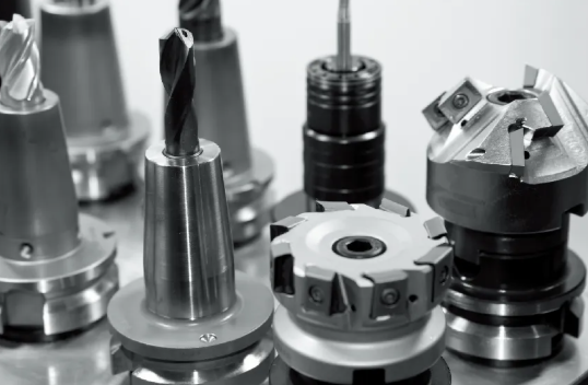
Think of machining processes as specialized tools in a manufacturing toolkit. You wouldn't use a hammer to drive screws, and you wouldn't use turning to create flat pockets. Each process excels at specific geometries while struggling with others. Let's break down the primary processes and what they do best.
Turning and Lathe Work: The Cylinder Specialists
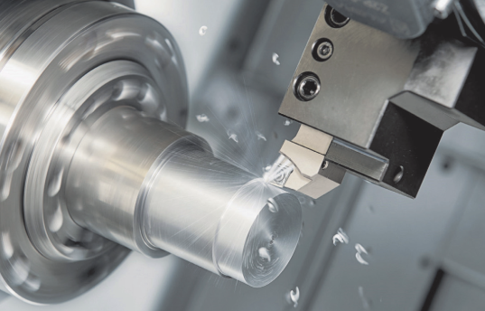
When your part revolves around a central axis, a lathe machine is your go-to solution. The workpiece spins while cutting tools remove material - perfect for shafts, bushings, pins, and any component with rotational symmetry.
What makes lathes particularly efficient? According to manufacturing comparisons, turning is generally faster than milling for cylindrical components and offers reduced operational costs for bulk production of symmetric parts. A skilled machinist can produce a precision shaft on a lathe in a fraction of the time required on a milling machine.
Modern CNC lathes can achieve tolerances of ±0.001" or better on diameters. They excel at producing:
- Shafts and spindles with multiple diameter steps
- Bushings and sleeves with precise inside and outside diameters
- Threaded components including screws, studs, and lead screws
- Tapered parts like collets and tool holders
Even a mini lathe can produce remarkably precise small components - hobbyists and prototype shops often rely on benchtop lathes for watch parts, model components, and small fixtures. The limitation? Lathes struggle with flat surfaces, pockets, and features that don't revolve around the part's axis.
Milling: Master of Complex Geometries
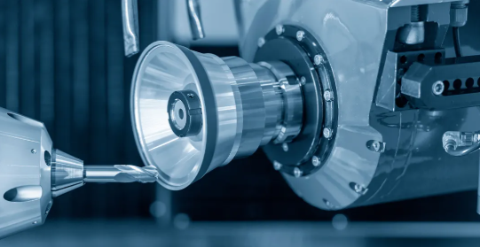
While lathes spin the workpiece, milling machines spin the cutting tool against a stationary (or moving) workpiece. This fundamental difference opens up entirely different geometric possibilities. A milling machine can create flat surfaces, pockets, slots, angles, and intricate 3D contours that would be impossible on a lathe.
Milling machines excel at:
- Flat surfaces and precision plates
- Pockets and cavities of various depths
- Complex 3D contours and sculptured surfaces
- Angular features and chamfers
- Hole patterns and mounting surfaces
The trade-off is efficiency. Manufacturing data confirms that milling takes longer than turning for round parts because it's fundamentally less suited to rotational geometry. If you're designing a cylindrical component and then adding milled flats, consider whether a different design could eliminate the milling operation entirely.
For smaller prototype work, a mini mill provides surprising capability in a compact footprint. These benchtop milling machines handle aluminum and brass easily, making them popular in educational settings and small machine shops where floor space is limited.
Drilling, Boring, and Reaming: The Hole-Making Hierarchy
Creating holes sounds simple, but precision hole-making involves three distinct operations, each with different capabilities:
- Drilling: Creates initial holes quickly and economically. Standard drilling produces holes with typical tolerances of ±0.003" to ±0.005" - acceptable for clearance holes but inadequate for precision fits.
- Boring: Enlarges and corrects drilled holes. Boring improves hole position accuracy and roundness, typically achieving tolerances of ±0.001" to ±0.002". It's essential when hole location matters as much as size.
- Reaming: The finishing operation that creates precise final dimensions with excellent surface finish. Reamers produce holes within ±0.0005" with surface finishes suitable for press fits and bearing installations.
These operations often work in sequence. A drilled hole provides rough stock removal, boring corrects position and roundness, and reaming delivers final size and finish. Skipping steps to save time often backfires - trying to ream an off-center drilled hole just produces an off-center reamed hole.
Grinding: When Standard Machining Isn't Precise Enough
Grinding occupies a special place in precision manufacturing. Using abrasive wheels rather than cutting edges, grinding achieves tolerances and surface finishes beyond what turning or milling can deliver economically.
Typical grinding capabilities include:
- Tolerances of ±0.0002" to ±0.0005" on diameters and surfaces
- Surface finishes of Ra 8-32 μin (0.2-0.8 μm)
- Processing of hardened materials that would destroy conventional cutting tools
Grinding becomes essential after heat treating, when parts have reached hardnesses that prevent conventional machining. A shaft heat-treated to 60 HRC cannot be turned economically - grinding is the only practical option for final sizing.
Understanding Machine Capabilities and Limitations
Every machining process operates within capability boundaries. Pushing beyond those boundaries is possible but expensive. Designing within them keeps costs manageable and lead times reasonable.
| Process | Typical Tolerance | Surface Finish (Ra) | Ideal Geometries | Relative Cost |
|---|---|---|---|---|
| Turning (Lathe) | ±0.001" to ±0.005" | 32-125 μin | Cylindrical parts, shafts, bushings | Low-Medium |
| Milling (3-axis) | ±0.002" to ±0.005" | 32-125 μin | Prismatic parts, pockets, flat surfaces | Medium |
| Milling (5-axis) | ±0.001" to ±0.003" | 16-63 μin | Complex contours, undercuts, compound angles | High |
| Drilling | ±0.003" to ±0.005" | 63-250 μin | Through holes, clearance holes | Low |
| Boring | ±0.001" to ±0.002" | 32-63 μin | Precision holes, corrected positions | Medium |
| Reaming | ±0.0005" to ±0.001" | 16-32 μin | Final-size precision holes | Medium |
| Grinding | ±0.0002" to ±0.0005" | 8-32 μin | Hardened surfaces, ultra-precision features | High |
Notice how tolerance capability correlates with cost. According to tolerance studies, moving from standard ±0.005" tolerances to precision ±0.001" tolerances can increase costs by 50-100%. Pushing to ultra-precision ±0.0005" territory may double or triple that again.
CNC Machining: Repeatability Meets Complexity
Computer Numerical Control (CNC) applies to turning, milling, and grinding - it's the automation layer that enables precision machinist parts production at scale. CNC doesn't change what processes can do geometrically; it changes how consistently and efficiently they do it.
CNC advantages include:
- Repeatability: The 100th part matches the first within measurable limits
- Complexity handling: Multi-axis machines access features from multiple angles in single setups
- Reduced human error: Programmed operations eliminate variations from operator fatigue or attention
- Documentation: Programs provide complete manufacturing records for traceability
5-axis CNC milling machines represent the pinnacle of geometric capability. According to process comparisons, 5-axis machines reduce setups, improve tool wear characteristics, and enable better surface finishes on contoured parts - but they require higher initial investment, complex programming, and skilled operators.
Designing for Manufacturing Economy
Understanding process capabilities directly impacts design decisions. Design for Manufacturing principles emphasize that design choices impact everything downstream - and once designs are finalized, engineers have much less flexibility to reduce costs.
Consider these process-aware design strategies:
- Match geometry to process: Cylindrical parts belong on lathes; prismatic parts belong on milling machines. Hybrid geometries requiring both processes cost more.
- Design for standard tooling: Inside corner radii should match available end mill sizes. A 0.375" radius pocket is economical; a 0.372" radius requires custom tooling.
- Minimize setups: Features accessible from one direction machine in one setup. Complex parts requiring multiple orientations multiply handling time and tolerance stack-up.
- Reserve precision for function: Apply tight tolerances only where functional requirements demand them. Commercial tolerances everywhere else keep costs manageable.
The most cost-effective part isn't the simplest design - it's the design that plays to available manufacturing capabilities rather than fighting against them.
With process selection understood, the next critical step is ensuring your machinist parts actually meet specifications once produced. Quality control and inspection methods verify that manufacturing intent becomes manufacturing reality.
Quality Control and Inspection Methods
Your machinist parts look great coming off the machine. But do they actually meet specifications? This question separates functional components from expensive paperweights. Quality control isn't an afterthought - it's the verification system that confirms manufacturing intent became manufacturing reality.
Here's a sobering truth: a part can appear perfect visually while being completely out of tolerance on critical dimensions. Without proper inspection protocols, you won't know until assembly fails or - worse - until a component fails in service. Let's explore the measurement tools and quality systems that prevent these costly surprises.
Inspection Tools and Techniques
Every tolerance specification on your drawing requires verification. The question is: which instrument provides the accuracy and resolution your measurement demands? Machinists measuring tools range from simple handheld devices to sophisticated computer-controlled systems, each suited to different precision levels and part geometries.
Handheld Measurement Tools
These workhorses handle the bulk of shop-floor dimensional verification:
- Calipers: Versatile instruments measuring outside dimensions, inside dimensions, depths, and steps. Digital calipers read to 0.0005" with typical accuracy of ±0.001" - suitable for commercial tolerance verification but insufficient for precision work.
- Micrometers: Higher precision than calipers, reading to 0.0001" with accuracy of ±0.0001" to ±0.0002". Different types handle outside diameters, inside bores, depths, and thread measurements. When tolerances tighten below ±0.001", micrometers become essential.
- Dial indicators: Measure displacement rather than absolute size - perfect for checking runout, flatness, and parallelism. A dial indicator mounted on a surface plate reveals flatness deviations invisible to direct measurement.
- Gauge blocks: Precision-ground metal blocks serving as dimensional standards. Wrung together in combinations, they create reference dimensions for calibrating other instruments and setting up comparative measurements.
For specialized verification, machinist measuring tools include thread gauges for confirming thread pitch and profile, pin gauges for go/no-go hole verification, and 123 blocks that provide precise reference surfaces for setup and inspection operations.
Coordinate Measuring Machines (CMM)
When part complexity exceeds what handheld tools can efficiently verify, CMM machines take over. These computer-controlled systems probe part surfaces in three-dimensional space, comparing measured coordinates against CAD geometry.
CMM capabilities include:
- Measuring complex 3D contours impossible to verify with traditional tools
- Automatic inspection routines that reduce operator influence on results
- Direct comparison to CAD models for GD&T verification
- Comprehensive reporting with statistical analysis
According to CNC machining quality guides, dimensional metrology with 3D scanning technology can provide highly accurate dimensional measurements and even create detailed 3D models for comparison to design specifications - critical for complex machinist parts requiring full geometric verification.
Beyond Dimensional Measurement
Complete quality verification extends beyond simple dimensions:
- Surface roughness testers: Measure Ra values to verify surface finish specifications
- Hardness testers: Confirm heat treatment results using Rockwell, Brinell, or Vickers methods
- Non-destructive testing (NDT): Ultrasonic, magnetic particle, and dye penetrant methods detect subsurface flaws without damaging parts
- Deburring tool inspection: Visual and tactile verification that deburring tools have properly removed machining burrs from edges and intersections
Even simple hand tools play quality roles. A pry tool might reveal loose fits during assembly verification, while deburring tools ensure edges meet smoothness requirements before parts ship.
Quality Assurance in Part Production
Individual measurements matter, but quality assurance encompasses the complete system ensuring every part meets specifications. This system includes defined inspection stages, documentation requirements, and statistical methods that catch problems before they multiply.
First-Article Inspection: Proving the Process
Before production runs, first-article inspection (FAI) verifies that your manufacturing process can consistently deliver conforming parts. According to industry standards, an FAI is a comprehensive review of the engineering documentation and the manufacturing process from raw materials through conversion, special processing, and functional testing.
A complete FAI package typically includes:
- Design records including drawings and bill of materials
- Raw material certifications with traceability (heat lot numbers, chemical composition)
- Ballooned drawings linking each dimension to its measured value
- Complete dimensional inspection report with actual measurements
- Measurement system traceability (gage IDs and calibration records)
- Special processing certifications (anodizing, plating, heat treating)
- Functional test results where applicable
For the buyer, an FAI confirms that design requirements have been understood and that the supplier's manufacturing process is capable of consistently delivering good parts. For the supplier, it's an opportunity to validate manufacturability and establish the production process before committing to volume.
Any significant change - design revision, manufacturing process change, new tooling, or facility move - typically triggers a new FAI to revalidate the process.
In-Process and Final Inspection Protocols
Quality checkpoints throughout manufacturing catch deviations before they propagate through subsequent operations:
- Incoming material inspection: Verify raw material certifications and spot-check dimensions before machining begins
- First-piece approval: Measure the first part from each setup before running the batch
- In-process checks: Periodic measurements during production runs to detect tool wear or thermal drift
- Post-operation inspection: Verify critical dimensions after each major machining operation
- Final inspection: Complete dimensional verification against drawing requirements before shipping
- Visual inspection: Check for surface defects, scratches, burrs, and cosmetic issues
Documentation and Traceability
Proper documentation transforms inspection data into actionable quality records. Essential documents include:
- Inspection reports: Recorded measurements for each verified dimension
- Certificates of Conformance (CoC): Formal declarations that parts meet specified requirements
- Material certifications: Mill test reports tracing material composition and properties
- Gage calibration records: Documentation that inspection instruments are accurate and traceable to national standards
The dimensional record must link each measurement to the gage used and its calibration status. This traceability ensures measurements are meaningful - a reading from an uncalibrated instrument has no quality value.
Statistical Process Control for Production Consistency
For production runs, individual part inspection isn't enough. Statistical Process Control (SPC) monitors the manufacturing process itself, identifying trends before they produce out-of-tolerance parts.
SPC techniques include:
- Control charts: Plot measured values over time to distinguish normal variation from assignable causes
- Process capability studies (Cpk): Quantify how well the process centers within tolerance limits
- Trend analysis: Detect gradual shifts indicating tool wear or environmental changes
- Sample inspection plans: Statistically valid sampling that balances inspection cost against risk
According to quality inspection methodologies, implementing SPC techniques helps monitor and control the manufacturing process in real-time, identifying and addressing issues as they arise rather than discovering problems after the entire batch is complete.
The power of SPC lies in prevention. Rather than sorting good parts from bad after production, SPC maintains process conditions that prevent bad parts from being made. For high-volume machinist parts production, this approach dramatically reduces scrap and rework costs while ensuring batch-to-batch consistency.
Quality isn't inspected into parts - it's built in through capable processes and verified through systematic measurement.
Understanding quality control helps you evaluate what to expect from manufacturing partners. But another fundamental decision awaits: should you buy standard catalog parts or invest in custom-machined components? The next section explores when each approach makes sense.
Standard Parts vs Custom Machined Components
You've explored materials, tolerances, processes, and quality control. Now comes a decision that can fundamentally reshape your project economics: should you source standard catalog parts or invest in custom-machined components? This isn't just a cost question - it's a strategic choice affecting lead times, design flexibility, and long-term operational success.
Here's the reality many engineers overlook: recent research suggests that 1 in 5 consumers are willing to pay a 20% premium for personalized goods or services. That willingness extends into industrial applications where fit, function, and performance justify the investment. But standard parts have their place too. Let's break down when each approach delivers the best value.
When to Buy Off-the-Shelf vs Custom
Imagine you need a simple spacer for a prototype assembly. You could spend $200 having one custom-machined with a two-week lead time. Or you could grab a standard part from a catalog for $3, delivered overnight. The choice seems obvious - until you realize the catalog spacer is 0.020" too short and made from the wrong material for your application.
This scenario plays out constantly in manufacturing. The "cheaper" standard part requires secondary modifications, adds assembly complexity, or compromises performance in ways that cost far more than the apparent savings.
Scenarios Favoring Standard Parts
Standard components make sense when your requirements align with what mass production already delivers:
- Common dimensions and materials: If your specification matches catalog offerings, you benefit from economies of scale without compromise
- Immediate availability requirements: When downtime costs exceed customization benefits, grabbing a standard part from stock wins
- Small quantities with commercial tolerances: One-off needs for non-critical applications rarely justify custom tooling and setup costs
- Proven track record matters: Standard parts have been used across many applications, providing reliability data that new custom designs lack
- Multi-source availability: Standardized components can be sourced from multiple vendors, reducing supply chain risk
Think of standard parts like off-the-rack clothing. If your measurements match standard sizes, you get quality garments at reasonable prices with immediate availability. The value proposition breaks down only when fit becomes critical.
Scenarios Requiring Custom Parts
Custom machining becomes essential when standard offerings can't meet your functional requirements:
- Unique dimensions or geometries: Non-standard sizes, unusual shapes, or integrated features that don't exist in catalogs
- Special material requirements: Custom machining allows you to select specific materials that might not be available in pre-made parts - critical for durability, weight, or compatibility requirements
- Tight tolerance requirements: When precision exceeds what standard manufacturing delivers, custom machining provides exact specifications
- Proprietary designs: Components central to your competitive advantage shouldn't come from catalogs your competitors also access
- Consolidated functionality: Combining multiple standard parts into one custom component often reduces assembly time, potential failure points, and total cost
One manufacturer discovered they were using three different standard parts for their product line because no single standard part met all requirements. A custom solution consolidated those three parts into one, improving product performance while reducing inventory complexity.
Evaluating Total Cost of Ownership
The purchase price tells only part of the story. What really matters is total cost of ownership - the complete expense of acquiring, using, and supporting a component throughout its lifecycle.
| Factor | Standard Parts | Custom Machined Parts |
|---|---|---|
| Lead Time | Immediate to days (from stock) | Days to weeks (manufacturing required) |
| Unit Cost (Small Qty) | Lower - benefits from mass production | Higher - setup costs spread over few parts |
| Unit Cost (High Volume) | May exceed custom due to middleman margins | Often competitive once tooling amortized |
| Minimum Quantities | Often single-piece available | Varies; some shops have minimums |
| Design Flexibility | Limited to catalog offerings | Complete freedom within manufacturing limits |
| Quality Consistency | Varies by supplier reputation | Controlled through direct specifications |
| Material Options | Limited to common grades | Any machinable material available |
| Product Lifecycle Control | Supplier determines obsolescence | You control availability as long as needed |
| Replacement Part Sales | May flow to component supplier | Remain with your organization |
Consider hidden costs that don't appear on purchase orders. Standard parts typically mean stock, which adds carrying costs - warehousing, climate control, insurance, and inventory management. These carrying costs can add 20-30% to the apparent base price before any markup.
Custom parts often provide lower total cost of ownership through reduced material costs, reduced engineering workarounds, future expandability, lower inventory requirements, and simplified supplier relationships. When you're maintaining a tap and die set or wrench set for field service, having parts designed for your specific application simplifies everything.
The Semi-Standard Solution
Here's an option many overlook: custom parts don't always have to be built from the ground up. It's often possible for suppliers to adapt standard solutions to meet your specific needs - creating "semi-standard" parts that combine catalog economics with custom fit.
Many custom-built parts incorporate standardized features - standard thread forms, common bore sizes, or industry-standard mounting patterns. A tap die set might create standard threads on otherwise custom components. Your tap and die kit handles threading operations whether the part started as catalog stock or custom bar. This hybrid approach often offers time and cost benefits worth exploring before committing to fully custom alternatives.
Decision Framework: Standard or Custom?
Use this framework to evaluate your specific situation:
- Start with function: What does this part actually need to do? If standard parts fulfill that function completely, stop there.
- Evaluate fit: Custom-made parts have an overall better quality fit - but only matters when fit is critical to performance.
- Consider volume: Setup costs for custom parts amortize over quantity. One piece costs much more per unit than one hundred pieces.
- Assess timeline: Can you wait for custom manufacturing, or does your schedule demand immediate availability?
- Calculate modifications: If standard parts require secondary machining, special fasteners, or assembly workarounds, add those costs to the comparison.
- Project forward: Will you need these parts again? Custom tooling pays dividends over repeat orders.
- Evaluate supply risk: Standard parts can be discontinued without notice. Custom specifications remain producible as long as you maintain the drawings.
- Consider competitive advantage: Does this component differentiate your product? Proprietary designs shouldn't come from public catalogs.
When you're reaching for wrenches or a wrench tool to assemble prototypes, notice which components require modification, shimming, or workarounds. Those pain points often indicate where custom parts would deliver better value than the standard components you're fighting with.
The cheapest part isn't always the least expensive solution. Total cost of ownership - including engineering time, assembly labor, and downstream consequences - determines true value.
Whether you choose standard or custom components, success ultimately depends on finding manufacturing partners who understand your requirements and deliver consistently. The final section explores how to identify and evaluate machine shops that become reliable extensions of your engineering team.
Finding Reliable Machining Partners for Your Parts
You've mastered material selection, tolerance specifications, and quality control requirements. Now comes the decision that determines whether all that knowledge translates into successful components: choosing the right manufacturing partner. Searching for a "machinist near me" might generate dozens of results, but not every shop can deliver the precision, consistency, and communication your project demands.
Think of it this way - your specifications are only as good as the shop executing them. A partner with robust quality systems and industry-specific experience becomes an extension of your engineering team. The wrong choice means missed deadlines, out-of-spec parts, and frustrating rework cycles that derail your project timeline.
Evaluating Machine Shop Capabilities
How do you distinguish capable manufacturers from shops that overpromise and underdeliver? According to quality evaluation frameworks, assessing a machine shop's capabilities requires looking beyond equipment lists to evaluate the entire quality system - from certifications and inspection technology to personnel training and supply chain management.
Certifications: Your First Quality Indicator
Certifications demonstrate commitment to standardized quality management systems. They're not just plaques on the wall - they represent documented procedures, traceability systems, and continuous improvement processes that have been independently verified.
- ISO 9001: The baseline quality management certification indicating structured processes and documentation - look for this as a minimum requirement
- IATF 16949: Essential for automotive suppliers, this certification adds automotive-specific requirements for defect prevention and variation reduction
- AS9100: Required for aerospace manufacturing, adding traceability and configuration management requirements critical for flight-critical components
Compliance with these standards indicates the shop has well-documented procedures and traceability systems. When you're sourcing precision tools near me or evaluating machinists tools for sale, the supplier's certification status tells you whether their quality claims have been independently verified.
Machine Shop Equipment and Technology
Capabilities start with equipment, but extend far beyond the machine list. When evaluating CNC machining suppliers, ask for specific capability details:
- Machine types and sizes - can they handle your part dimensions and geometries?
- Spindle speeds and power - critical for efficient machining of your chosen materials
- Multi-axis capabilities - 5-axis machines reduce setups and improve accuracy on complex parts
- Inspection equipment - CMMs, surface testers, and calibrated measuring instruments matched to your tolerance requirements
Modern cnc machinist tools and inspection technology ensure parts meet specifications consistently. Shops investing in advanced equipment demonstrate commitment to precision manufacturing rather than just getting by with outdated machinery.
Process Control and Documentation
Effective quality systems perform in-process inspections throughout the machining cycle rather than relying solely on final inspection. Key process control indicators include:
- First Article Inspection (FAI): Comprehensive verification that initial parts meet requirements before full production begins
- Statistical Process Control (SPC): Real-time monitoring that tracks production data to prevent deviations rather than just detecting them
- Material traceability: Complete documentation linking raw material certifications to finished parts through the entire manufacturing process
- Calibration programs: Regular verification that all measuring instruments maintain accuracy traceable to national standards
A shop that provides inspection reports, certificates of conformity, and SPC data demonstrates process maturity that translates into consistent part quality.
Building Successful Manufacturing Partnerships
Beyond technical capabilities, successful manufacturing relationships depend on communication, responsiveness, and industry understanding. The best machine shop equipment means nothing if the team operating it doesn't understand your application requirements.
Industry-Specific Experience Matters
Each industry has unique demands that generic machining experience doesn't address. Automotive applications require PPAP documentation and zero-defect expectations. Medical devices demand validated processes and biocompatible materials. Aerospace components need full traceability and often non-destructive testing.
A qualified supplier should not only have industry-specific experience but also provide the documentation and validation tailored to your sector. Ask potential partners about their experience with applications similar to yours - the learning curve for industry-specific requirements can significantly impact both quality and delivery.
Communication and Responsiveness
Transparency is a strong indicator of quality capability. Reliable machine shops provide:
- Clear communication channels for discussing tolerances, design adjustments, and potential manufacturing challenges
- Responsive quoting that addresses questions promptly rather than leaving you waiting
- Proactive notification when issues arise rather than surprises at delivery
- Corrective action documentation showing how problems are investigated and prevented from recurring
Pay attention to how potential partners communicate during the quoting process. Their responsiveness before you're a customer typically reflects how they'll perform after you've placed orders.
Scalability and Lead Time Capabilities
Whether you're launching a new product or responding to demand surges, your manufacturing partner should scale with your needs. Evaluate:
- Prototype-to-production capability - can they handle both one-off development parts and volume orders?
- Lead time flexibility - what's their standard turnaround, and can they expedite when necessary?
- Capacity headroom - are they running at maximum utilization, or do they have bandwidth for your projects?
The ability to pivot quickly often separates good vendors from great partners. For time-sensitive projects, ask about rush capabilities and what premium applies for accelerated delivery.
A Real-World Example: Automotive Precision Manufacturing
Consider what these evaluation criteria look like in practice. Shaoyi Metal Technology exemplifies how specialized capabilities serve demanding applications. Their IATF 16949 certification specifically addresses automotive industry requirements, while their Statistical Process Control practices ensure batch-to-batch consistency that automotive OEMs demand.
What sets specialized partners apart is application understanding. Shaoyi's capability for chassis assemblies and custom metal bushings demonstrates the range of machinist parts production that automotive applications require - from structural components bearing dynamic loads to precision bushings controlling motion and reducing friction. Their rapid lead times, sometimes as fast as one working day, address the prototype-to-production speed that automotive development cycles demand.
This type of specialized capability matters when your machinist tool requirements extend beyond generic manufacturing into industry-specific applications where experience directly impacts quality outcomes.
Key Takeaways for Selecting a Machining Partner
Finding the right manufacturing partner requires systematic evaluation rather than choosing based on price alone. Use this summary to guide your selection process:
- Verify certifications: ISO 9001 minimum, with industry-specific certifications (IATF 16949, AS9100) for specialized applications
- Assess equipment capabilities: Ensure their machine shop equipment matches your part geometries, materials, and tolerance requirements
- Evaluate quality systems: Look for documented processes including first-article inspection, SPC, and material traceability
- Check inspection technology: CMMs and calibrated instruments appropriate for your precision requirements
- Confirm industry experience: Prior work in your application area reduces learning curves and quality risks
- Test communication responsiveness: How they handle inquiries predicts how they'll handle your orders
- Understand scalability: Confirm they can support both current needs and future volume growth
- Request references: Proven track records in similar applications provide confidence beyond capability claims
- Evaluate total value: Factor in quality consistency, delivery reliability, and technical support alongside unit pricing
The right machining partner doesn't just make your parts - they contribute expertise that improves your designs, catches potential issues early, and delivers consistent quality that protects your reputation.
Throughout this guide, you've gained practical knowledge spanning materials, tolerances, processes, quality control, and supplier evaluation. These fundamentals apply whether you're engineering precision aerospace components, developing automotive systems, or building custom equipment for specialized applications. Armed with this understanding, you're prepared to specify machinist parts confidently, communicate effectively with manufacturing partners, and ensure your components perform exactly as designed.
Frequently Asked Questions About Machinist Parts
1. What parts do machinists make?
Machinists produce a wide range of custom components including shafts, bushings, spacers, brackets, fixtures, and jigs. These precision parts serve industries from aerospace to automotive, encompassing everything from simple steel bolts to complex titanium bone screws for medical implants. Hydraulic components, antilock brake parts, and automobile pistons are common examples. Specialized manufacturers like Shaoyi Metal Technology produce automotive-specific machinist parts including chassis assemblies and custom metal bushings with IATF 16949 certification.
2. What do machinists charge per hour?
CNC machine hourly rates vary significantly by equipment type and complexity. Mid-sized CNC lathes typically run $50-$110 per hour, while horizontal CNC mills range from $80-$150 per hour. Advanced 5-axis CNC machines command $120-$300+ per hour, and Swiss lathes fall between $100-$250 per hour. These rates reflect equipment costs, operator expertise, and tolerance requirements. Shops with certifications like IATF 16949 for automotive applications may charge premium rates reflecting their quality systems and specialized capabilities.
3. What are the 7 major parts of a CNC machine?
The seven key components of a CNC machine include: the Machine Control Unit (MCU) serving as the operational brain; input devices like computers or microcontrollers for program loading; the drive system controlling axis movement; the machine tool performing cutting operations; the feedback system ensuring positioning accuracy; the bed and table providing workpiece support; and the cooling system managing heat during machining. Understanding these components helps when specifying machinist parts, as machine capabilities directly affect achievable tolerances and surface finishes.
4. How do I choose the right material for custom machined parts?
Material selection depends on application requirements including load conditions, environmental exposure, temperature range, weight constraints, and tolerance needs. Aluminum 6061 offers excellent machinability and is cost-effective for prototypes. Steel grades provide superior strength for high-stress applications. Stainless steel 304 or 316 delivers corrosion resistance for marine or food-grade uses. Engineering plastics like Delrin offer chemical resistance and weight savings. Consider machinability ratings alongside performance requirements - harder materials take longer to machine and cost more to produce at tight tolerances.
5. What tolerances can CNC machining achieve?
Standard CNC machining efficiently achieves tolerances of ±0.005 inches (±0.13mm) without special procedures. Precision work reaches ±0.001 inches (±0.025mm) but requires specialized equipment and environmental controls, increasing costs by 50-100%. Ultra-precision tolerances of ±0.0001 inches demand grinding operations and temperature-controlled environments, multiplying costs by 10-24x. Match tolerance specifications to actual functional requirements - over-tolerancing non-critical dimensions unnecessarily inflates manufacturing costs without improving performance.