 Small batches, high standards. Our rapid prototyping service makes validation faster and easier —

CNC Prototyping Machine Decisions: From Material Choice To Final Part
What Makes CNC Prototyping Machines Essential for Product Development
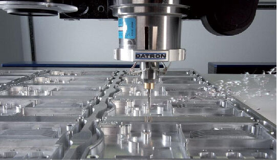
Ever wondered how engineers transform a digital design into a physical part you can actually hold and test? That's exactly where CNC prototyping machines come into play. These computer-controlled systems take your CAD (Computer-Aided Design) files and convert them into functional prototypes by precisely removing material from a solid block—whether that's aluminum, steel, or engineering plastics.
Think of it this way: you upload a 3D model, and the machine follows programmed toolpaths to carve out your exact design with tolerances as tight as thousandths of an inch. This subtractive manufacturing approach differs fundamentally from 3D printing, which builds parts layer by layer. Instead, a CNC prototyping machine starts with more material than you need and cuts away everything that isn't your part.
From Digital Design to Physical Reality
The beauty of CNC prototyping lies in its direct digital-to-physical workflow. Once your design file loads into the machine, cutting tools follow exact paths to shape the material according to precise specifications. This process enables rapid machining and quick iteration—when you spot a design flaw, you simply update the CAD model and run another prototype without waiting for new tooling or molds.
What separates prototype CNC operations from production machining? Three key factors: speed, flexibility, and iteration capability. While production runs prioritize volume and consistency across thousands of parts, CNC prototyping focuses on getting functional test pieces into engineers' hands as quickly as possible. Modern high-speed machines can turn a CAD file into a finished prototype in hours rather than days or weeks.
Why Subtractive Manufacturing Still Dominates Prototyping
Despite the buzz around 3D printing, CNC machining prototyping remains the gold standard for functional testing. Why? The answer comes down to material integrity and real-world performance.
CNC prototyping bridges the gap between concept and production-ready parts by creating prototypes from the exact same materials used in final manufacturing—giving engineers accurate insights into how components will actually perform under real-world conditions.
When you machine a CNC prototype from a solid block of aluminum or steel, the finished part maintains the full structural integrity of that material. There are no layer lines, no bonding points, no weak spots where delamination might occur. This matters tremendously when your prototype needs to withstand stress testing, thermal cycling, or actual field use.
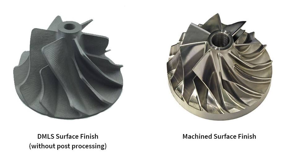
According to manufacturing experts, the primary drawback of additive prototyping is that resulting parts usually lack the structural integrity of solid materials. The points where layers join together simply can't match the strength of a machined part cut from a single piece of material.
A CNC prototyping machine also delivers superior surface finishes—from mirror-smooth to custom textures—without the stepped appearance common in 3D-printed parts. This flexibility proves essential when prototypes need to slide against other components, fit precisely into assemblies, or undergo market testing where appearance matters.
Types of CNC Prototyping Machines and Their Ideal Applications
Now that you understand why CNC prototyping remains essential, the next question becomes: which machine type fits your project? Not all proto machining equipment works the same way, and choosing the wrong configuration can mean wasted time, budget overruns, or compromised part quality. Let's break down each major machine category so you can match capabilities to your specific prototype requirements.
Understanding Axis Configurations for Your Project Needs
When engineers talk about CNC machines, they often reference "axes"—but what does that actually mean for your prototype? Simply put, each axis represents a direction the cutting tool or workpiece can move. More axes mean more flexibility in approaching complex geometries from different angles.
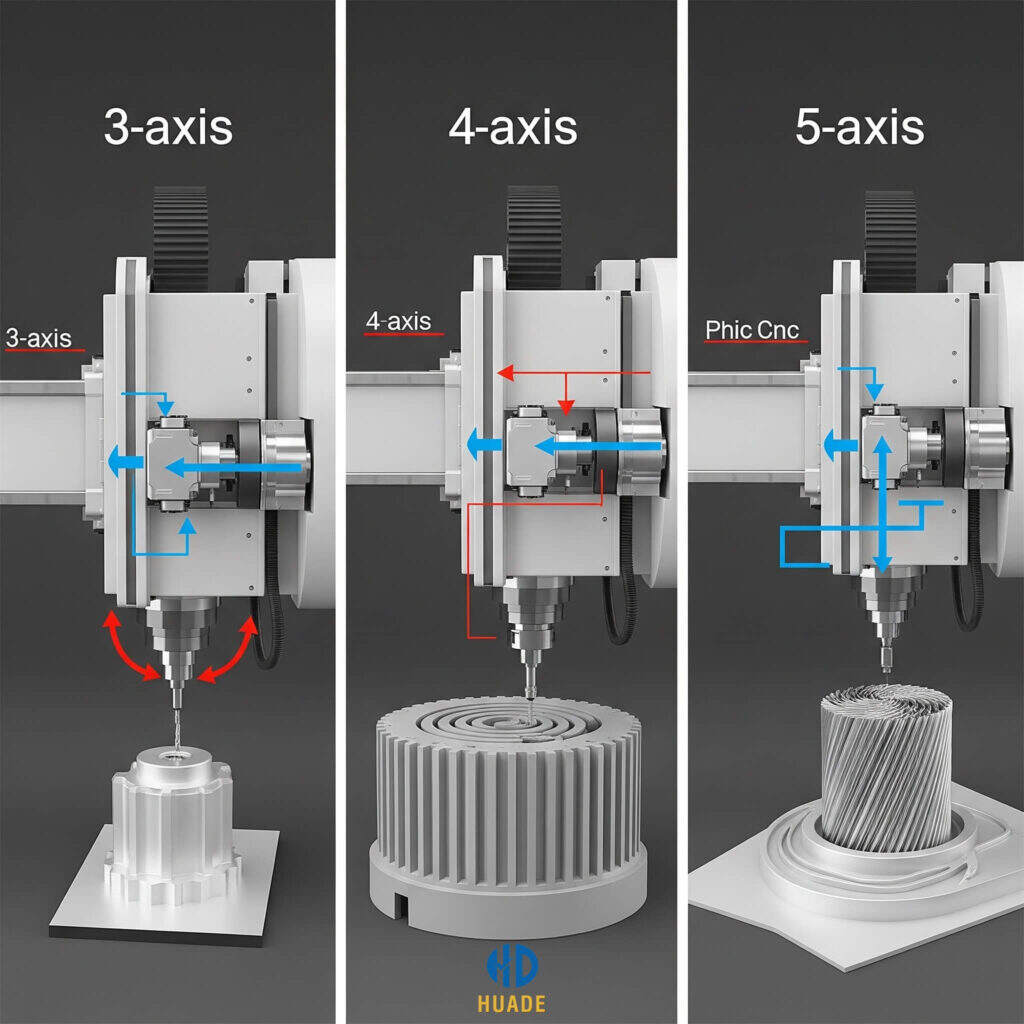
3-Axis CNC Mills represent the workhorses of proto machining. The cutting tool moves along three linear directions: X (left-right), Y (front-back), and Z (up-down). These machines excel at creating flat surfaces, pockets, slots, and straightforward geometric features. If your prototype has mostly planar surfaces with holes and basic contours, a 3-axis mill handles the job efficiently and cost-effectively.
However, 3-axis machines have a limitation you'll notice quickly. Since the tool can only approach from above, any feature on the sides or bottom of your part requires repositioning the workpiece—and each repositioning introduces potential alignment errors. For simpler CNC milling parts like brackets, enclosure panels, or mounting plates, this rarely causes issues.
4-Axis CNC Mills add a rotational axis (typically called the A-axis) that allows the workpiece to rotate during machining. This configuration shines when your prototype includes cylindrical features, helical cuts, or wrap-around details. Imagine machining a complex grip pattern around a cylindrical handle—a 4-axis setup completes this in one operation rather than multiple setups.
5 Axis CNC Machining Services take flexibility to another level entirely. By adding two rotational axes, the cutting tool can approach virtually any surface at optimal angles without repositioning. This capability proves indispensable for aerospace turbine blades, medical implants with organic contours, and automotive components with complex compound curves.
According to RapidDirect's machining guide, 5-axis machining reduces setups dramatically, improves surface finishes on contoured surfaces, and extends tool life by maintaining optimal cutting angles. The tradeoff? Higher machine costs, more complex programming, and the need for skilled CAM designers.
Matching Machine Capabilities to Prototype Complexity
Beyond milling configurations, two other machine types deserve consideration for your prototyping toolkit.
CNC Lathes operate fundamentally differently from mills. Instead of rotating the cutting tool, lathes spin the workpiece while a stationary tool removes material. This approach is ideal for producing CNC milling components that are cylindrical or have rotational symmetry—shafts, rods, bushings, and threaded fasteners.
Modern CNC lathes often incorporate live tooling capabilities, meaning rotating cutting tools can perform drilling and milling operations while the part remains mounted. As noted by Zintilon's machine comparison, this feature enables creating complex parts with both turned and milled features in a single setup, dramatically increasing efficiency for prototypes that combine cylindrical bodies with machined flats or cross-holes.
CNC Routers fill a different niche in proto machining. These machines typically feature larger work envelopes and excel at processing softer materials like wood, plastics, foam, and composites. If you're prototyping large panels, signage, architectural models, or composite components, routers offer speed advantages over mills—though with somewhat reduced precision on harder materials.
The key distinction? CNC mills use robust, rigid frames designed to absorb cutting forces when machining metals. CNC routers prioritize speed and work area size, making them less suitable when you need to produce a precision CNC machine part from aluminum or steel but perfect for large-format plastic or composite prototypes.
| Machine Type | Axis Configuration | Best Prototyping Applications | Complexity Level | Typical Work Envelope |
|---|---|---|---|---|
| 3-Axis CNC Mill | X, Y, Z linear | Flat surfaces, pockets, slots, brackets, enclosures | Basic to Moderate | 12" x 12" x 6" to 40" x 20" x 20" |
| 4-Axis CNC Mill | X, Y, Z + A rotation | Cylindrical features, helical cuts, wrap-around patterns | Moderate | Similar to 3-axis with rotary capacity |
| 5-Axis CNC Mill | X, Y, Z + A, B rotation | Aerospace turbines, medical implants, complex contours | High | Varies widely; often 20" x 20" x 15" |
| CNC Lathe | X, Z (+ C, Y with live tooling) | Shafts, rods, bushings, threaded parts, rotational symmetry | Basic to Moderate | Up to 24" diameter, 60" length typical |
| CNC Router | X, Y, Z (3 or 5-axis) | Large panels, signage, composites, wood, plastics, foam | Basic to Moderate | 48" x 96" to 60" x 120" common |
Choosing the right machine type ultimately comes down to matching your prototype's geometry and material requirements to the machine's strengths. A cylindrical component with precise threads? CNC milling turning on a lathe makes sense. Complex aerospace bracket with compound angles? 5-axis CNC machining services deliver what you need. Large composite panel with routed pockets? A CNC router handles it efficiently.
Understanding these distinctions helps you communicate effectively with machine shops and make informed decisions about whether to invest in specific equipment or outsource particular operations. But machine type is only half the equation—the materials you choose will equally influence your prototyping success.
Material Selection Guide for CNC Prototype Manufacturing
You've identified the right machine type for your project—but here's where many prototyping efforts stumble: material selection. Choosing the wrong material doesn't just affect machining efficiency; it can completely invalidate your prototype testing results. Why? Because the material you select directly determines mechanical strength, thermal behavior, chemical resistance, and ultimately whether your prototype accurately represents how the final production part will perform.
Think about it this way: if you're developing an automotive bracket that needs to withstand engine bay temperatures, prototyping in standard ABS plastic gives you misleading data. The part might look perfect, but it won't behave anything like the aluminum or steel component you'll eventually manufacture. Smart material selection ensures your machined metal parts or plastic prototypes deliver meaningful test results you can actually trust.
Metal Selection for Functional Prototype Testing
Metals remain the backbone of functional prototyping when structural integrity, heat resistance, or production-accurate testing matters. Each metal category offers distinct advantages depending on your application requirements.
Aluminum Alloys dominate proto machining for good reason. Milled aluminum offers an exceptional combination of light weight, corrosion resistance, and machinability that keeps costs manageable while delivering production-representative results. Aluminum 6061 is the workhorse alloy—easy to machine, readily available, and suitable for everything from aerospace structural components to automotive brackets. When you need higher strength, 7075 aluminum provides superior tensile properties, though it's slightly more challenging to cut.
According to Timay CNC's prototyping guide, aluminum's excellent machinability reduces production time and tool wear, making it ideal for rapid prototyping and cost-effective production. This translates directly to faster iteration cycles when you're refining designs.
Steel Variants become essential when your prototype must replicate the strength characteristics of production components. Mild steel offers affordability for structural testing, while stainless steel grades like 304 and 316 provide corrosion resistance for medical or marine applications. If wear resistance matters—think gears, shafts, or sliding surfaces—tool steels deliver the hardness your functional tests require.
Brass fills a specific niche in metal machining parts for prototypes. Its excellent machinability and natural corrosion resistance make it ideal for electrical connectors, decorative hardware, and plumbing fittings. The aesthetic appeal of polished brass also serves well when prototypes need to represent final product appearance for stakeholder presentations or market testing.
Titanium enters the conversation when you're prototyping for aerospace, medical implants, or high-performance applications where strength-to-weight ratio is critical. Yes, titanium is significantly harder to machine and more expensive than aluminum—but when your production part will be titanium, there's simply no substitute for testing with metal machined from the actual material.
Engineering Plastics That Simulate Production Materials
Not every prototype requires metal. Engineering plastics offer cost advantages, faster machining speeds, and material properties that often closely match injection-molded production parts. The key is selecting plastics that accurately simulate your final material's behavior.
ABS (Acrylonitrile Butadiene Styrene) represents one of the most popular choices for CNC plastic prototype work. ABS cnc machining delivers parts with high impact resistance, good stiffness, and excellent surface finish capability. It machines cleanly without melting or gumming, making it ideal for enclosures, housings, and consumer product prototypes. The limitation? ABS offers limited heat resistance and poor UV stability, so outdoor or high-temperature applications need different materials.
PEEK (Polyetheretherketone) occupies the high-performance end of the plastics spectrum. According to EcoRepRap's PEEK machining guide, this material operates at temperatures up to 250°C (482°F) while maintaining exceptional chemical resistance and mechanical strength. With tensile strength ranging from 90 to 120 MPa, PEEK approaches metal-like performance in a lightweight package. Aerospace, medical devices, and oil and gas industries rely on PEEK prototypes when parts must withstand demanding mechanical conditions.
The same source notes that PEEK's density of 1.3 to 1.4 g/cm³ makes it significantly lighter than metals—one reason it serves as a metal substitute in weight-critical applications. However, PEEK's complex production process means higher material costs, so reserve it for prototypes where its unique properties are genuinely necessary.
Delrin (Acetal/POM) excels for mechanical components like gears, bushings, and sliding parts. Its low friction coefficient, dimensional stability, and fatigue resistance make it ideal for prototypes that must demonstrate mechanical function rather than just fit and form.
Nylon offers excellent wear resistance and toughness for prototypes subjected to repeated stress or abrasion. It's commonly selected for functional testing of mechanical assemblies where durability matters.
Polycarbonate brings optical clarity and shatter resistance—perfect for prototypes where transparency is essential, such as safety shields, lenses, or display covers.
Specialty Materials for Demanding Applications
Some prototyping applications push beyond standard metals and plastics. Ceramic cnc machining, while challenging, enables prototypes for high-temperature environments like kiln components, aerospace thermal barriers, or specialized electrical insulators. Ceramics offer exceptional heat resistance and hardness but require diamond tooling and careful process control.
Composites including carbon fiber reinforced polymers deliver outstanding strength-to-weight ratios for aerospace and automotive structural prototypes—though machining these materials demands specialized dust extraction and tool selection to manage abrasive fiber content.
| Material Category | Specific Materials | Best Applications | Machining Considerations | Prototype Use Cases |
|---|---|---|---|---|
| Aluminum Alloys | 6061, 7075, 2024 | Aerospace structures, automotive brackets, enclosures | Excellent machinability; use sharp tools and proper coolant | Lightweight structural testing, thermal conductivity validation |
| Steel Variants | Mild steel, 304/316 stainless, tool steel | Structural components, medical devices, wear parts | Slower speeds than aluminum; requires rigid setups | Strength testing, corrosion resistance validation |
| Brass | C360 (free-machining), C260 | Electrical connectors, decorative hardware, fittings | Excellent machinability; produces quality surface finish | Electrical conductivity testing, aesthetic prototypes |
| Titanium | Grade 2, Grade 5 (Ti-6Al-4V) | Aerospace components, medical implants, marine parts | Low speeds, high coolant flow; generates significant heat | Biocompatibility testing, high-performance validation |
| Engineering Plastics | ABS, PEEK, Delrin, Nylon, Polycarbonate | Consumer products, mechanical components, housings | Higher speeds than metals; watch for heat buildup | Functional testing, injection molding simulation |
| Ceramics | Alumina, Zirconia, Silicon Carbide | High-temp insulators, wear components, electrical parts | Diamond tooling required; brittle material handling | Thermal barrier testing, electrical insulation validation |
Selecting the right material ultimately comes down to matching your prototype's test requirements to material properties. Will you be validating structural loads? Choose metals with appropriate strength characteristics. Testing fit and function for a consumer product? Engineering plastics often provide faster, more economical iterations. Evaluating high-temperature performance? PEEK or ceramics might be your only viable options.
But material selection is only part of the equation. Even the perfect material choice can result in failed prototypes if your design doesn't account for manufacturability constraints—which brings us to the critical design principles that separate successful CNC prototypes from expensive scrap.
Design for Manufacturability Principles in CNC Prototyping
You've selected the ideal machine type and material for your prototype—but here's where many projects hit unexpected roadblocks. A design that looks perfect in CAD can become a machining nightmare, driving up costs and extending lead times. Why? Because CNC machining prototype success depends heavily on understanding what's actually achievable when cutting tools meet material.
Design for machining isn't about limiting creativity. It's about designing smart so your prototypes come off the machine exactly as intended—without surprise setups, broken tools, or compromised features. Let's walk through the critical DFM principles that separate successful CNC milled parts from expensive learning experiences.
Tolerance Specifications That Ensure Prototype Success
Tolerances define how much dimensional variation is acceptable in your finished part. Here's the reality: tighter tolerances cost more—sometimes exponentially more. According to Hubs' CNC design guide, typical tolerances of ±0.1 mm work for most proto machining applications, while feasible tolerances can reach ±0.02 mm when necessary.
But here's what many engineers miss: the relationship between tolerance and cost isn't linear. Dropping from ±0.1 mm to ±0.05 mm might add 20% to machining time. Pushing to ±0.02 mm could double or triple costs because you're now dealing with machine accuracy limits, thermal expansion considerations, and potentially specialized inspection equipment.
For CNC machine design optimization, consider these tolerance guidelines:
- Standard features: Specify ±0.1 mm (±0.004") for non-critical dimensions—this is readily achievable on any quality CNC machine without special processes
- Functional interfaces: Use ±0.05 mm (±0.002") where parts must mate precisely or bearings require specific fits
- Critical features only: Reserve ±0.025 mm (±0.001") or tighter for genuinely critical dimensions—and expect to pay significantly more
- Same-setup features: When two features must maintain tight relative position, design them to be machined in a single setup to eliminate refixturing error
The key insight? Apply tight tolerances selectively. If every dimension on your drawing shows ±0.01 mm, you're signaling to the machine shop that either you don't understand manufacturing, or every feature genuinely requires precision grinding—and they'll quote accordingly.
Wall Thickness and Feature Depth Limitations
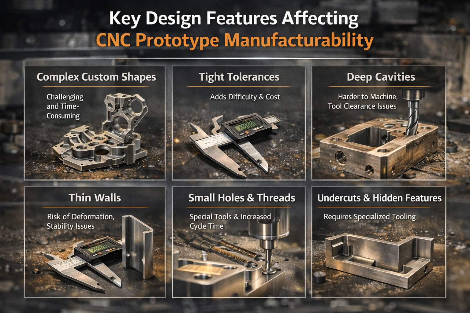
Thin walls vibrate during machining. Vibrating walls produce poor surface finish, inaccurate dimensions, and sometimes catastrophic failures. Different materials have different minimum wall thickness requirements:
- Metals (aluminum, steel, brass): Recommended minimum 0.8 mm; feasible down to 0.5 mm with careful machining strategies
- Engineering plastics: Recommended minimum 1.5 mm; feasible down to 1.0 mm—plastics are prone to deflection and heat-induced warping
- Unsupported thin features: Consider the ratio of wall height to thickness—tall thin walls act like tuning forks under cutting forces
Pocket and cavity depths present similar challenges. According to Five Flute's DFM guidelines, aim for pocket depths no greater than 6 times the tool diameter for standard operations. Depths up to 10 times tool diameter start becoming challenging regardless of available tooling.
Why does depth-to-width ratio matter so much? End mills have limited cutting length—typically 3 to 4 times their diameter. Deeper pockets require longer tools that deflect more, generate more vibration, and leave visible milling marks on sidewalls. Extended-reach endmills exist, but they machine slower and may still produce inconsistent surface quality.
Internal Corner Radii and Undercut Considerations
Here's a fundamental constraint that surprises many designers: CNC cutting tools are round. That means every internal corner on your part will have a radius—there's no way around it.
The recommended internal corner radius equals at least one-third of the cavity depth. If you're machining a 12 mm deep pocket, plan for corner radii of 4 mm or larger. This allows the machinist to use appropriately sized tools that won't chatter or break.
Practical guidelines for internal corners:
- Standard approach: Specify corner radii slightly larger than the tool radius to allow circular toolpath motion rather than sharp direction changes—this produces better surface finish
- Sharp corners needed? Consider adding T-bone or dogbone undercuts at corners instead of demanding impossibly small radii
- Floor radii: Use 0.5 mm, 1 mm, or specify "sharp" (meaning flat)—these match standard end mill geometries
Undercuts—features that can't be accessed directly from above—require special tooling. Standard T-slot and dovetail cutters handle common undercut geometries, but custom undercuts may require special tools or multiple setups. The rule of thumb: add clearance equal to at least four times the undercut depth between the machined wall and adjacent internal surfaces.
Hole and Thread Specifications
Holes seem simple, but their specifications significantly impact proto machining efficiency. For optimal results:
- Diameter: Use standard drill bit sizes whenever possible—metric or imperial standards are readily available and reduce cost
- Depth: Recommended maximum depth is 4 times the hole diameter; typical depth up to 10 times diameter; feasible to 40 times diameter with specialized deep-hole drilling
- Blind holes: Drill bits leave a 135-degree conical bottom—if you need a flat bottom, specify end mill machining (slower) or accept the cone
- Minimum practical diameter: 2.5 mm (0.1") for standard machining; smaller features require micro-machining expertise and specialty tooling
Thread specifications follow similar logic. According to Hubs' guidelines, threads down to M1 are feasible, but M6 or larger is recommended for reliable CNC threading. For smaller threads, taps work but carry breakage risk. Thread engagement beyond 3 times the nominal diameter provides no additional strength—the first few threads carry the load.
Avoiding Common Design Pitfalls in CNC Prototyping
Understanding how DFM principles differ between 3-axis and 5-axis machining helps you design parts that match available equipment—or justify the investment in more capable machines.
3-Axis Machining Design Rules:
- Align all features to one of six principal directions (top, bottom, four sides)
- Plan for multiple setups if features exist on different faces—each setup adds cost and potential alignment error
- Design features accessible from directly above; undercuts require special tooling
- Consider how the part will be held in a vise—flat, parallel surfaces simplify fixturing
5-Axis Machining Advantages:
- Complex contoured surfaces can be machined with consistent tool engagement, reducing milling marks
- Multiple faces machined in single setup—improved accuracy between features
- Undercuts and angled features accessible without special tooling
- Trade-off: higher machine costs and programming complexity
The parts of a CNC mill that matter most for DFM are the spindle (which determines maximum tool size and speed), the work envelope (which limits part dimensions), and the axis configuration (which determines accessible geometries). Understanding these constraints before finalizing your CAD model prevents costly redesigns.
Remember: the goal of DFM isn't to constrain creativity—it's to ensure your CNC machining prototype comes out right the first time. With these principles in hand, you're ready to understand the complete workflow that transforms your optimized design into a finished prototype.
The Complete CNC Prototyping Workflow from Design to Finished Part
You've designed your part with manufacturability in mind and selected the right material—but what actually happens between uploading your CAD file and holding a finished prototype? Surprisingly, most proto machining resources skip this critical workflow, jumping straight from "submit your file" to "receive your part." That leaves engineers guessing about the intermediate steps where problems often occur.
Understanding the complete workflow helps you prepare better files, communicate more effectively with machine shops, and troubleshoot issues when prototypes don't meet expectations. Let's walk through every stage from digital design to inspected, finished CNC machining parts.
-
Prepare and export your CAD file in a CNC-compatible format
Your CNC machine doesn't read native CAD files directly. You need to export your design in a format that preserves geometric accuracy for CAM software processing. According to JLCCNC's CAD preparation guide, the best formats for CNC machining include STEP (.stp, .step), IGES (.igs, .iges), and Parasolid (.x_t, .x_b). STEP files offer the most universal compatibility while preserving solid geometry data that CAM systems need for accurate toolpath generation.
Avoid mesh-based formats like STL or OBJ—they work for 3D printing but break smooth curves into triangular facets that produce inaccurate CNC milled surfaces. If you're working in software like Fusion 360, SolidWorks, or Inventor, the STEP export process takes just a few clicks. -
Import into CAM software and define machining setup
CAM (Computer-Aided Manufacturing) software translates your 3D model into the specific cutting instructions your machine needs. Popular CAM platforms include Fusion 360 CAM, Mastercam, SolidCAM, and HSMWorks. During import, you'll define the stock material dimensions—essentially telling the software how big the raw material block is before machining begins. -
Generate toolpaths for each machining operation
This step is where the magic happens. The CAM programmer selects cutting tools, defines cutting speeds and feeds, and creates the specific paths the cutter will follow. A typical CNC machining part might require multiple toolpaths: roughing passes to remove bulk material quickly, semi-finishing passes to approach final dimensions, and finishing passes that achieve your specified surface quality and tolerances. -
Run simulation and verify toolpaths
Before any metal gets cut, CAM software simulates the entire machining sequence. This virtual machining reveals potential collisions, gouges, or missed material before they become expensive mistakes on real parts. Sample machining simulations catch problems that would otherwise only appear when you're staring at a ruined prototype. -
Post-process to machine-specific G-code
Different CNC machines speak slightly different dialects of G-code. A post-processor translates the generic CAM toolpaths into the specific command syntax your particular machine controller understands—whether that's a Fanuc, Haas, Mazak, or other control system. The output is a text file containing every move, speed change, and tool change the machine will execute. -
Set up workholding and load material
Workholding—how you secure the raw material during cutting—directly affects accuracy and surface finish. Vises work well for rectangular blocks, while chucks hold cylindrical stock on lathes. Fixture plates with clamps handle irregular shapes. The key consideration: ensure the workholding doesn't interfere with any cutting paths and provides rigid support to prevent vibration. -
Execute machining operations in sequence
With G-code loaded and material secured, machining begins. Operations typically follow a logical sequence: face the top surface flat, rough out major features, drill holes, machine pockets, then execute finishing passes. Each tool change follows programmed instructions, with the machine automatically selecting the next cutter from its tool carousel. -
Perform post-machining operations
The part coming off the machine isn't quite finished. Deburring, surface finishing, and quality inspection transform a rough CNC milled workpiece into a completed prototype ready for testing.
CAD to CAM Translation for Optimal Toolpaths
The transition from CAD to CAM is where your design file becomes a manufacturing reality—and where many prototype projects encounter their first obstacles. Understanding this translation helps you prepare files that process smoothly.
When importing your CAD file, the CAM software analyzes the geometry to identify machinable features: pockets, holes, slots, contours, and surfaces. Modern CAM systems can automatically recognize many standard features and suggest appropriate toolpaths. However, complex geometries or unusual configurations may require manual programming intervention.
Toolpath selection involves balancing multiple factors:
- Roughing strategies: Adaptive clearing or high-efficiency milling removes material quickly while managing tool engagement and heat generation
- Tool selection: Larger tools remove material faster but can't access tight corners; smaller tools reach everywhere but cut slowly
- Stepover and stepdown: These parameters control how much the tool moves sideways and downward between passes—smaller values produce better surfaces but take longer
- Cutting speeds and feeds: Material-specific parameters that balance cutting efficiency against tool life and surface quality
According to machining preparation guidelines, your CAD file directly impacts toolpath quality. Clean geometry without duplicate surfaces, properly closed solids, and realistic feature sizes all contribute to smoother CAM processing and better finished parts.
Post-Machining Operations That Complete Your Prototype
Machining gets your part to near-final shape, but post-processing operations determine whether your prototype meets professional standards. These steps often receive less attention than they deserve—yet they directly affect both functionality and appearance.
Deburring and Edge Treatment
Cutting tools leave sharp edges and small burrs—thin ridges of material pushed aside during machining. According to Mekalite's post-processing guide, burrs can harm both safety and function of finished parts. Deburring methods range from manual hand tools for simple parts to mechanical tumbling for batch processing. The choice depends on part geometry, material, and required edge condition.
For precision prototypes, manual deburring with scrapers, files, or abrasive tools gives the operator control over exactly how much material is removed. Automated tumbling works well for less critical parts or larger quantities but may round edges more than desired.
Surface Finishing Options
The as-machined surface might be perfectly acceptable for functional testing—but many prototypes require additional finishing. Common options include:
- Bead blasting: Creates uniform matte texture that hides minor machining marks
- Polishing: Produces smooth, reflective surfaces—essential for sealing surfaces or aesthetic prototypes
- Anodizing (aluminum): Adds corrosion resistance and color while creating a hard surface layer
- Powder coating: Provides durable, decorative finish in virtually any color
- Passivation (stainless steel): Enhances corrosion resistance by removing free iron from the surface
Some applications require CNC grinding services to achieve surfaces smoother than standard milling can produce. Grinding removes material with abrasive wheels rather than cutting edges, achieving mirror-like finishes and extremely tight dimensional tolerances when necessary.
Quality Testing for CNC Machined Parts
Before your prototype leaves the shop, inspection verifies that critical dimensions meet specifications. Basic dimensional checks use calipers, micrometers, and gauge pins. More complex parts may require coordinate measuring machines (CMMs) that probe dozens of points and generate detailed inspection reports.
Quality testing for cnc machined parts typically covers:
- Critical dimensions specified on your drawing
- Hole diameters and positions
- Surface finish measurements (Ra values)
- Thread gauging for tapped holes
- Visual inspection for defects or cosmetic issues
The inspection process catches problems before prototypes reach your test bench—saving time and preventing invalid test results from dimensionally incorrect parts.
With your prototype now machined, finished, and inspected, you're holding a part ready for functional testing. But before you finalize your prototyping approach, it's worth understanding how CNC machining compares to alternative methods—and when each approach makes the most sense for your specific requirements.
CNC Prototyping Versus Alternative Manufacturing Methods
Now that you understand the complete workflow from CAD file to finished prototype, a critical question remains: is CNC machining actually the right choice for your project? Rapid cnc prototyping delivers exceptional results for many applications—but it's not always the optimal path. Depending on your quantity requirements, material needs, tolerance specifications, timeline, and budget, alternatives like 3D printing, injection molding, or even manual machining might serve you better.
The challenge? Most resources either champion one method while dismissing others or provide surface-level comparisons that don't help you make informed decisions. Let's build a practical framework you can apply to your specific prototyping requirements.
When CNC Beats 3D Printing for Prototypes
The CNC versus 3D printing debate often generates more heat than light. Both methods transform digital designs into physical parts—but they serve fundamentally different purposes.
According to Zintilon's prototyping comparison, the key difference lies in how each process builds a part. CNC uses a subtractive process, removing material from a solid block to form the shape, while 3D printing uses an additive approach, building parts layer by layer. This foundational difference influences everything from material options and part accuracy to cost and speed.
Choose CNC rapid prototyping when:
- Material properties matter: CNC machines work with aluminum, steel, titanium, brass, and engineering plastics—the actual materials you'll use in production. 3D printing materials, while improving, still can't match the mechanical properties of machined metals
- Structural integrity is critical: CNC prototypes are cut from solid material, maintaining full structural integrity. 3D-printed parts have layer bonds that create potential weak points, especially under stress or thermal cycling
- Surface finish requirements are demanding: CNC produces smooth surfaces requiring minimal post-processing. 3D-printed parts typically show visible layer lines unless extensively finished
- Tight tolerances are non-negotiable: CNC routinely achieves ±0.05 mm tolerances, with ±0.025 mm feasible for critical features. Most 3D printing processes struggle to match this precision
- Functional testing requires production-representative parts: When your prototype must behave exactly like the final product under real-world conditions, machining from the same material eliminates variables
Choose 3D printing when:
- Speed trumps everything: 3D printing can produce parts in hours rather than days. For early-stage concept validation where you need something physical immediately, additive wins
- Complex internal geometries are essential: Lattice structures, internal channels, and organic shapes that would require extensive multi-axis machining print easily
- Cost for single units matters most: According to the same source, for small quantities, 3D printing is typically cheaper because it doesn't require specialized tools, fixtures, or custom setups
- Iteration speed matters more than material accuracy: When you're exploring design directions rather than validating production intent, fast and cheap beats precise and expensive
Volume Thresholds That Determine Your Best Approach
Quantity requirements dramatically shift the economics of prototyping methods. What makes sense for five parts becomes impractical for fifty—and completely wrong for five hundred.
Rapid prototyping cnc machining hits a sweet spot between one-off production and volume manufacturing. According to manufacturing cost analysis, if you plan on producing five or more high-quality prototypes, CNC can be more cost-effective than 3D printing as the per-unit cost decreases with increased volume.
Injection Molding Comparison:
Injection molding enters the conversation when quantities climb higher. The challenge? Tooling costs create a significant upfront investment—typically thousands to tens of thousands of dollars for even simple molds. However, Protolabs notes that on-demand manufacturing options can bridge the gap, offering aluminum molds suitable for up to 10,000-plus parts at lower tooling costs than traditional steel molds.
The crossover point depends on part complexity, but generally:
- 1-10 parts: CNC machining rapid prototyping or 3D printing typically wins on total cost
- 10-100 parts: CNC often remains competitive, especially for metal parts or tight tolerances
- 100-1,000 parts: Soft tooling or rapid injection molding starts becoming cost-effective for simpler geometries
- 1,000+ parts: Production injection molding with proper tooling becomes the clear choice for plastic parts
Manual Machining Considerations:
Don't overlook skilled manual machinists for certain prototype scenarios. When you need a single complex part that requires judgment calls during fabrication—perhaps a repair prototype or a one-off fixture—an experienced machinist with conventional equipment sometimes delivers faster and cheaper than programming a CNC operation. The tradeoff is repeatability: manual machining can't duplicate parts with the consistency CNC provides.
| Method | Best Volume Range | Material Options | Typical Tolerances | Lead Time | Cost Considerations |
|---|---|---|---|---|---|
| CNC Machining | 1-500 parts | Metals (aluminum, steel, titanium, brass), engineering plastics, composites | ±0.05 mm standard; ±0.025 mm feasible | 1-5 days typical for prototypes | Higher per-part cost but no tooling; decreases with volume |
| 3D Printing (FDM/SLA/SLS) | 1-50 parts | Primarily plastics; limited metal options at high cost | ±0.1-0.3 mm typical | Hours to 1-2 days | Low per-part cost for simple geometries; scales linearly |
| Rapid Injection Molding | 50-10,000 parts | Thermoplastics (ABS, PP, PE, nylon, etc.) | ±0.05-0.1 mm | 1-3 weeks (includes tooling) | $1,500-$10,000 tooling; very low per-part cost |
| Production Injection Molding | 10,000+ parts | Full range of thermoplastics and some thermosets | ±0.05 mm or better | 4-12 weeks (steel tooling) | $10,000-$100,000+ tooling; lowest per-part cost at volume |
| Manual Machining | 1-5 parts | Same as CNC (metals, plastics) | ±0.1-0.25 mm typical | Hours to days depending on complexity | Lower setup cost; higher labor cost; limited repeatability |
Making Your Decision:
Your prototyping method selection ultimately comes down to prioritizing these five factors:
- Quantity: How many parts do you need now, and how many might you need later?
- Material requirements: Must the prototype use production-intent materials, or can you simulate with alternatives?
- Tolerance needs: Are tight tolerances essential for function, or is approximate geometry sufficient?
- Timeline: Is speed critical, or can you wait for higher-quality results?
- Budget: What's your total cost constraint, including potential rework from lower-quality methods?
As Protolabs' prototyping guide emphasizes, prototype models help design teams make more informed decisions by obtaining invaluable data from performance testing. The more accurately your prototyping method represents final production, the more reliable your test data becomes.
For many engineering teams, CNC machining rapid prototyping offers the best balance of material accuracy, dimensional precision, and reasonable cost—especially when prototypes must undergo functional testing or regulatory evaluation. But the right answer for your project depends on your specific requirements across all five decision factors.
With a clear understanding of when each method excels, you're better equipped to choose your prototyping approach. But one major decision remains: should you invest in in-house CNC capabilities, or partner with external prototyping services?
In-House CNC Machines Versus Outsourced Prototyping Services
You've determined that CNC machining is the right approach for your prototype—but now comes a decision that can significantly impact both your budget and development velocity: should you invest in your own equipment or partner with a cnc prototyping service? This isn't just a financial calculation. It's a strategic choice that affects how quickly you can iterate, how much control you maintain over proprietary designs, and whether your engineering team spends time machining parts or designing better products.
Surprisingly, most resources gloss over this decision or push you toward whatever the author happens to sell. Let's break down the real factors that should guide your choice.
Calculating True Cost of In-House CNC Prototyping
The appeal of owning your own CNC equipment seems obvious: no waiting for quotes, no shipping delays, complete control over your schedule. But the true cost extends far beyond the machine purchase price.
According to Fictiv's ROI analysis, when factoring in loaded labor rates, machine utilization, and maintenance, outsourcing to digital manufacturing networks often delivers higher ROI for teams producing fewer than 400-500 prototypes per year. That number surprises many engineering managers who assume in-house equipment pays for itself quickly.
Here's what drives that calculation: your fully loaded labor rate—salary plus benefits plus overhead—typically runs 1.9 to 2.3 times base salary. Every hour your mechanical engineer spends operating a machine or calibrating a printer is an hour not spent on design improvements. And machinist time, while less expensive, still adds significant cost per prototype.
When in-house CNC makes financial sense:
- High iteration frequency: If you're running multiple prototype cycles weekly, eliminating quote turnaround and shipping time compounds into major schedule advantages
- Proprietary design protection: Sensitive IP that you can't risk sharing with external vendors—even under NDA—may justify the investment
- Volume exceeds 400-500 prototypes annually: At this threshold, fixed equipment costs spread across enough parts to beat per-unit outsourcing pricing
- Long-term strategic capability: Building internal manufacturing expertise that supports future production or provides competitive advantage
- Simple, repetitive geometries: When your typical prototype doesn't require specialized capabilities, basic 3-axis equipment handles most needs
According to JLCCNC's analysis, purchasing a CNC machine means complete control of your production process and the ability to handle urgent orders on your schedule. However, the high initial investment and specialized knowledge required for operation and maintenance can add significantly to long-term operating costs.
When Outsourcing Delivers Better Value
For many engineering teams, prototype machining services offer advantages that outweigh ownership benefits. The math changes dramatically when you factor in variable demand, capital constraints, and access to specialized capabilities.
Outsourcing makes sense when:
- Demand fluctuates significantly: Some months you need twenty prototypes; other months you need two. Paying for idle machine capacity destroys ROI
- Capital preservation matters: Quality CNC equipment costs $50,000 to $500,000+. That capital might generate better returns invested in product development or market expansion
- Specialized capabilities are required: 5-axis machining, EDM, precision grinding, or exotic materials demand equipment investments that rarely make sense for occasional prototype needs
- Speed-to-first-part beats internal capacity: Many online cnc machining services deliver parts in 1-3 days—faster than you could set up an in-house job if your machine is already running other work
- Engineering time is your constraint: As Fictiv's analysis notes, every hour saved from the shop floor is an hour invested in innovation. If your engineers are designing while a prototype machine shop handles fabrication, you're likely moving faster overall
The flexibility advantage deserves emphasis. Choosing CNC machining services lets you adjust order quantity according to production needs without carrying equipment capacity you don't always use. When demand spikes, you scale up. When it drops, you're not paying for idle machines.
If you're searching for cnc milling services near me or exploring regional options like cnc prototype services georgia, you'll find the landscape has transformed. Digital manufacturing networks now provide instant quoting, DFM feedback, and quality guarantees that rival or exceed what most in-house operations achieve.
The Hybrid Approach: Best of Both Worlds
Here's what the smartest engineering teams have figured out: the choice isn't binary. A hybrid strategy combining basic in-house capabilities with outsourced specialized work often delivers optimal results.
Consider this hybrid model:
- In-house basic capability: A desktop or benchtop CNC mill handles quick iterations, simple geometries, and urgent same-day needs. Investment: $5,000-$30,000
- Outsourced precision work: Complex parts, tight tolerances, and specialized materials go to professional prototype machine shop partners with appropriate equipment
- Outsourced volume runs: When you need 20+ identical prototypes for testing distribution, external services scale more efficiently
This approach preserves capital while maintaining rapid iteration capability for early-stage development. Your engineers can run quick test parts internally, then send production-intent prototypes to shops with the precision equipment and quality systems those parts demand.
Fictiv's research supports this strategy, suggesting teams use in-house 3D printing for early concept validation, fit checks, or lightweight fixtures while outsourcing machining and precision parts to digital manufacturing networks for faster, repeatable, inspection-ready results.
The key insight? Match your sourcing decision to each prototype's requirements rather than forcing everything through a single channel. Quick-and-dirty concept models might run on a desktop machine in your lab. Functional prototypes heading to customer evaluation deserve the quality and documentation a professional cnc prototyping service provides.
With your sourcing strategy defined, the final consideration becomes matching your prototyping approach to your specific industry's requirements—because automotive, aerospace, and medical applications each bring unique constraints that influence every decision from material selection to quality documentation.
Industry-Specific CNC Prototyping Requirements and Applications
You've established your sourcing strategy and understand the fundamentals of proto machining—but here's where generic advice falls short. A prototype machining approach that works perfectly for consumer electronics might fail catastrophically in aerospace applications. Why? Because each industry brings specific certification requirements, material constraints, tolerance expectations, and documentation standards that fundamentally shape how prototypes must be produced and validated.
Understanding these industry-specific demands before you start prototyping prevents costly rework, rejected parts, and compliance headaches. Let's examine what prototype machining actually looks like across four demanding sectors.
Automotive Prototype Requirements That Ensure Production Viability
Automotive prototyping operates under intense pressure: components must perform reliably at temperature extremes, withstand vibration and impact, and ultimately translate seamlessly into mass production. Prototype machined parts that can't demonstrate production viability waste engineering time and delay vehicle programs.
Chassis and Structural Components:
Chassis assemblies demand cnc prototype machining with exceptional dimensional accuracy. Suspension mounting points, subframe brackets, and structural reinforcements typically require tolerances of ±0.05 mm or tighter to ensure proper assembly and load distribution. Material selection usually centers on high-strength aluminum alloys like 6061-T6 or 7075-T6 for weight savings, though steel variants remain essential for high-stress applications.
- Critical tolerances: Mounting hole positions within ±0.025 mm; flatness specifications of 0.05 mm per 100 mm for mating surfaces
- Material traceability: Documentation linking each prototype to specific material heat lots and certifications
- Surface treatments: Anodizing or e-coating prototypes to simulate production corrosion protection
- Testing compatibility: Designing prototypes to interface with production fixtures and test equipment
Powertrain Components:
Engine and transmission prototypes face thermal cycling, high loads, and tight packaging constraints. Metal cnc machining for powertrain applications often involves aluminum housings, steel shafts, and precision-machined bearing surfaces. Cnc aluminum prototype components for engine mounts and brackets must withstand sustained temperatures exceeding 150°C while maintaining dimensional stability.
- Thermal considerations: Material selection accounting for thermal expansion matching between mating components
- Surface finish requirements: Sealing surfaces often requiring Ra 0.8 μm or better to prevent fluid leakage
- Geometric tolerancing: True position callouts for bearing bores and shaft centerlines
Interior Elements:
Interior prototypes serve different purposes—often focused on fit, finish, and human factors validation rather than structural performance. Precision prototyping machining for interior components might involve softer materials like ABS or polycarbonate to simulate injection-molded production parts.
For automotive teams demanding the highest quality assurance, facilities with IATF 16949 certification provide documented quality management systems specifically designed for automotive supply chains. Shaoyi Metal Technology, for example, combines this automotive-specific certification with SPC-controlled processes to deliver high-tolerance chassis assemblies and precision components that meet OEM requirements from prototype through production.
Aerospace Applications: Certified Materials and Documentation
Aerospace prototype cnc machining operates in a different universe of regulatory scrutiny. Every material, process, and inspection must be documented, traceable, and often certified by approved sources. According to American Micro Industries, AS9100 certification extends ISO 9001 requirements with aerospace-specific controls, emphasizing risk management, configuration control, and product traceability.
- Material certifications: Aerospace prototypes typically require materials from approved suppliers with mill test reports documenting chemical composition and mechanical properties
- Process documentation: Every machining operation, heat treatment, and surface finish must follow documented procedures with recorded parameters
- First article inspection: Comprehensive dimensional reports comparing prototype features to drawing specifications
- NADCAP accreditation: Special processes like heat treating, chemical processing, and non-destructive testing often require NADCAP-accredited facilities
Common aerospace prototype materials include titanium alloys (Ti-6Al-4V) for structural components, aluminum 7075 for airframe parts, and specialized nickel superalloys for high-temperature applications. Each material brings specific machining challenges—titanium's low thermal conductivity and work hardening tendencies demand careful speed and feed selection.
As noted by 3ERP's certification guide, AS9100 emphasizes rigorous risk management, configuration control, and product traceability, ensuring that every component meets stringent aerospace industry standards. Prototypes intended for flight testing face even more demanding requirements, potentially including FAA conformity inspections.
Medical Device Prototyping Compliance Considerations
Medical device prototyping introduces biocompatibility requirements that don't exist in other industries. The materials contacting human tissue must be proven safe, and manufacturing processes must be validated to ensure consistent results. According to regulatory guidelines, ISO 13485 certification provides the quality management framework specific to medical device production.
- Biocompatible materials: Titanium (Grade 2 and Grade 5), surgical stainless steel (316L), PEEK, and medical-grade polymers dominate device prototyping
- Surface finish requirements: Implantable devices may require mirror polishes (Ra <0.1 μm) to minimize tissue irritation and bacterial adhesion
- Cleaning and passivation: Post-machining processes to remove contaminants and enhance corrosion resistance
- Documentation for regulatory submissions: Design history files linking prototypes to design inputs, verification testing, and material certificates
The FDA's 21 CFR Part 820 Quality System Regulation governs how medical device manufacturers must document design, manufacturing, and tracking processes. Even prototype iterations may need to follow these requirements if they're used in design verification testing that supports regulatory submissions.
Risk management takes center stage in medical prototyping. As industry experts note, ISO 13485 mandates a focus on customer satisfaction by ensuring products meet safety and performance criteria, with companies required to demonstrate the ability to identify and mitigate risks associated with medical device use.
Consumer Electronics Prototyping: Enclosures and Thermal Management
Consumer electronics prototyping prioritizes aesthetics, thermal performance, and manufacturability validation. Unlike aerospace or medical applications, regulatory requirements are less demanding—but market expectations for fit, finish, and functionality remain extremely high.
Enclosure Development:
According to Think Robotics' enclosure design guide, custom enclosures unlock significant advantages for production products, including size optimization, integrated mounting features, and brand differentiation. CNC machined prototypes validate these designs before committing to injection molding tooling.
- Material simulation: Machining ABS or polycarbonate prototypes that approximate injection-molded production parts
- Surface finish matching: Bead blasting, polishing, or texturing to simulate production cosmetics
- Tolerance validation: Confirming that PCB mounting features, button cutouts, and connector openings align properly
- Assembly sequence testing: Verifying that components install correctly and enclosure halves mate as designed
Thermal Management Components:
Heat sinks, thermal spreaders, and cooling system components often require cnc aluminum prototype iterations to validate thermal performance before production commitment. The same source notes that aluminum offers excellent thermal conductivity, EMI shielding, and premium appearance—making it ideal for both functional and aesthetic prototyping.
- Fin geometry optimization: Machining multiple heat sink variations to test thermal performance
- Interface flatness: Ensuring thermal contact surfaces meet specifications (often 0.05 mm or better)
- Integrated designs: Prototyping enclosures that double as heat sinks, validating both thermal and mechanical requirements simultaneously
Electronics prototyping timelines often compress dramatically as product launch dates approach. This makes rapid turnaround capability essential—prototype machine shops that can deliver parts in days rather than weeks provide significant competitive advantage during final development sprints.
Each industry's unique requirements shape every aspect of prototype cnc machining—from initial material selection through final inspection and documentation. Understanding these constraints before you begin prototyping ensures your parts meet not just dimensional specifications but also the regulatory, quality, and performance standards your application demands.
Making Smart CNC Prototyping Decisions for Your Project
You've now explored the complete landscape of proto machining—from machine types and materials to DFM principles and industry-specific requirements. But here's the reality: all that knowledge only creates value when you apply it to actual decisions. Whether you're launching your first prototype project or refining an established development workflow, the difference between success and frustration comes down to making informed choices at each stage.
Let's synthesize everything into actionable frameworks you can apply immediately—regardless of where you stand in your prototyping cnc journey.
Your CNC Prototyping Decision Framework
Every successful prototype project requires clear thinking across five interconnected decision areas. Getting any one wrong can undermine an otherwise solid approach. Here's how to work through each systematically:
1. Machine Selection Alignment
Match your part's geometric complexity to appropriate equipment. Simple brackets and housings? 3-axis milling handles them efficiently. Cylindrical components with cross-features? Consider 4-axis or CNC turning with live tooling. Complex contoured surfaces requiring access from multiple angles? 5-axis becomes necessary despite higher costs. Don't pay for capability you don't need—but don't force inappropriate equipment to handle geometries beyond their efficient range.
2. Material-to-Application Matching
Your prototype's material should represent production intent whenever possible. Testing an aluminum bracket machined from 6061-T6 gives you accurate data about how the production part will perform. Testing that same bracket in ABS plastic tells you almost nothing useful about structural behavior. Reserve material substitutions for early-stage concept validation where speed matters more than accuracy.
3. DFM Integration from Day One
Design for manufacturability isn't a final checkpoint—it's a design philosophy. Build internal corner radii, appropriate wall thicknesses, and realistic tolerances into your CAD model from the start. Retrofitting DFM principles into a mature design creates unnecessary revision cycles and delays. The engineers who prototype fastest are those who design with machining constraints already internalized.
4. Sourcing Strategy That Matches Volume and Complexity
Low iteration frequency with varied complexity? Outsource to flexible prototype machining services. High iteration frequency with simple geometries? Consider in-house capability. Complex specialized requirements beyond your equipment? Partner with shops offering advanced capabilities. The hybrid approach—basic in-house capability supplemented by external specialists—often delivers optimal results.
5. Industry Compliance Awareness
Understand your industry's documentation and certification requirements before machining starts. Automotive OEMs expect PPAP documentation. Aerospace applications demand material traceability and first article inspection. Medical devices require biocompatibility verification. Building these requirements into your prototyping workflow from the beginning prevents costly rework when compliance questions arise later.
The most successful CNC prototyping programs treat each prototype as a learning opportunity that advances both the product design and the team's manufacturing knowledge—not just a part to check off a development milestone.
For Beginners Starting Their First Prototype Project:
- Start with a simpler geometry to learn the workflow before tackling your most complex design
- Choose a forgiving material like aluminum 6061—it machines easily and tolerates minor programming errors
- Specify standard tolerances (±0.1 mm) unless specific features genuinely require tighter control
- Partner with an experienced cnc prototyping service for your first few projects—their DFM feedback teaches you what works and what causes problems
- Document what you learn from each iteration to build institutional knowledge
For Experienced Engineers Optimizing Workflow:
- Analyze your last ten prototype projects—where did delays occur, and what design changes were most common?
- Build DFM checklists specific to your typical part geometries and materials
- Establish relationships with multiple suppliers offering different capabilities and lead times
- Consider rapid cnc machine investments for high-frequency iteration needs where turnaround time directly impacts development velocity
- Implement design reviews that specifically address manufacturability before releasing to fabrication
Scaling from Prototype to Production Successfully
The transition from cnc prototypes to production manufacturing represents one of the most critical—and frequently botched—phases of product development. According to UPTIVE's prototype-to-production guide, this phase helps catch design, manufacturing, or quality issues, validate manufacturing processes, identify bottlenecks, and assess suppliers and partners in terms of quality, responsiveness, and lead times.
What separates smooth transitions from painful ones? Several key factors:
Design Stability Before Scaling:
Rushing to production tooling while design changes continue wastes money and time. As industry experts note, prototype with CNC to validate design, then transition to production methods when the design is frozen. Each revision to a production mold costs thousands of dollars and weeks of delay. CNC machined prototypes cost a fraction of that to modify—use that flexibility to finalize your design before committing to volume production processes.
Process Validation Through Low-Volume Runs:
According to Star Rapid's manufacturing guide, since CNC machined parts are high fidelity, there is little difference between a prototype and a production part. This makes CNC ideal for low-volume production runs that validate manufacturing processes before full-scale commitment. Running 50-100 parts through your intended production workflow reveals issues that single prototypes miss.
Supplier Capability Assessment:
Your prototype supplier may or may not be your production partner. Evaluate potential production sources based on:
- Quality certifications appropriate to your industry (IATF 16949, AS9100, ISO 13485)
- Demonstrated capacity to scale from rapid prototype machining to volume production
- Lead time reliability and communication responsiveness
- Statistical process control capabilities ensuring consistency across production runs
Documentation That Transfers:
Production requires more than just a CAD file. Build comprehensive technical data packages including:
- Complete engineering drawings with GD&T specifications
- Material specifications with approved alternatives
- Surface finish and coating requirements
- Inspection criteria and sampling plans
- Lessons learned from prototype iterations
The organizations that accelerate most effectively from cnc machined prototypes to full production share a common characteristic: they partner with manufacturing capabilities that span the entire journey. Working with a single supplier from first prototype through volume production eliminates handoff delays, preserves institutional knowledge, and ensures consistency.
For automotive applications in particular, partnering with capable manufacturing partners accelerates this prototype-to-production journey significantly. Shaoyi Metal Technology exemplifies this approach—their ability to scale seamlessly from rapid prototyping to mass production, with lead times as fast as one working day, makes them ideal for automotive supply chain acceleration where development timelines compress constantly.
Whether you're machining your first prototype or your thousandth, the principles remain consistent: match your approach to your requirements, design with manufacturing in mind, and build relationships with capable partners who can grow with your needs. The machined prototypes you produce today become the foundation for the production parts your customers will rely on tomorrow.
Frequently Asked Questions About Proto Machining
1. What is CNC machining and how does it work for prototyping?
CNC machining is a subtractive manufacturing process where computer-controlled cutting tools remove material from a solid block to create precise parts. For prototyping, this means uploading a CAD design file, which gets translated into toolpaths that guide the machine to carve out your exact design with tolerances as tight as ±0.025 mm. Unlike 3D printing, CNC prototypes maintain full material structural integrity because they're cut from solid blocks of aluminum, steel, or engineering plastics—giving you production-representative parts ideal for functional testing.
2. What materials can be used in CNC prototype machining?
CNC prototyping works with a wide range of materials including metals like aluminum alloys (6061, 7075), stainless steel, brass, and titanium for structural testing. Engineering plastics such as ABS, PEEK, Delrin, nylon, and polycarbonate simulate injection-molded production parts. Specialty materials including ceramics and carbon fiber composites are also machinable for high-temperature or lightweight applications. Material selection should match your prototype's testing requirements—structural load validation needs metals, while fit and function testing often works well with plastics.
3. How do I choose between CNC machining and 3D printing for prototypes?
Choose CNC machining when material properties, structural integrity, tight tolerances (±0.05 mm or better), and surface finish are critical—especially for functional testing with production-intent materials. 3D printing works better for early concept validation, complex internal geometries, and situations where speed matters more than material accuracy. For quantities above five high-quality prototypes, CNC often becomes more cost-effective. IATF 16949-certified facilities like Shaoyi Metal Technology provide CNC prototyping with quality assurance for demanding automotive applications.
4. What tolerances can CNC machining achieve for prototype parts?
Standard CNC machining achieves tolerances of ±0.1 mm for typical features, while functional interfaces requiring precise fits can reach ±0.05 mm. Critical features can be machined to ±0.025 mm, though costs increase significantly at this precision level. The key is applying tight tolerances selectively—only specify precision tolerances where function genuinely requires them. Features machined in a single setup maintain better relative positioning than those requiring refixturing between operations.
5. Should I invest in in-house CNC equipment or outsource prototyping?
The decision depends on your prototype volume and iteration frequency. In-house equipment makes financial sense when you produce over 400-500 prototypes annually, require protection for proprietary designs, or need immediate turnaround for frequent iterations. Outsourcing delivers better value when demand fluctuates, specialized capabilities are needed, or capital preservation matters. Many teams use a hybrid approach—basic in-house capability for quick iterations combined with professional CNC prototyping services for precision work and volume runs.