 Small batches, high standards. Our rapid prototyping service makes validation faster and easier —

Machining Of Parts Exposed: Cost Drivers & Selection Secrets Revealed
What Machining Really Means in Modern Manufacturing
Ever wondered what is machining and why it remains the backbone of precision manufacturing? At its core, the machining definition is straightforward: it's any process where a cutting tool removes material from a workpiece to create a desired shape. Think of it like sculpting, but instead of clay, you're working with metals, plastics, and composites using precision-controlled equipment.
Machining is a subtractive manufacturing process in which cutting tools systematically remove material from raw stock to produce components with precise dimensions, tight tolerances, and smooth surface finishes.
The machining meaning extends beyond simple cutting. It encompasses a family of operations including turning, milling, drilling, and grinding, each using specialized tools to achieve specific geometries. When you define machining in practical terms, you're describing the controlled interaction between a harder cutting edge and softer work material, where relative motion between tool and workpiece produces the final shape.
The Subtractive Manufacturing Principle
Subtractive manufacturing stands in direct contrast to additive processes like 3D printing. While additive methods build objects layer by layer, machine work operates on the opposite principle. You start with more material than you need and strategically remove everything that isn't part of the final design.
According to Dassault Systèmes, subtractive manufacturing delivers smoother surface finishes and tighter dimensional tolerances compared to additive alternatives. This precision advantage explains why machining is a preferred choice for functional components requiring exact specifications.
The key differences include:
- Material approach: Subtractive starts with solid stock; additive builds from nothing
- Surface quality: Machined surfaces achieve superior smoothness
- Tolerance capability: Tighter dimensional control through material removal
- Material options: Broader range of metals and engineering plastics
From Raw Stock to Finished Component
The transformation journey in machine working follows a logical progression. An unfinished workpiece, whether a metal bar, block, or casting, enters the process with excess material. Through carefully controlled cutting operations, that raw stock becomes a finished product matching engineering specifications.
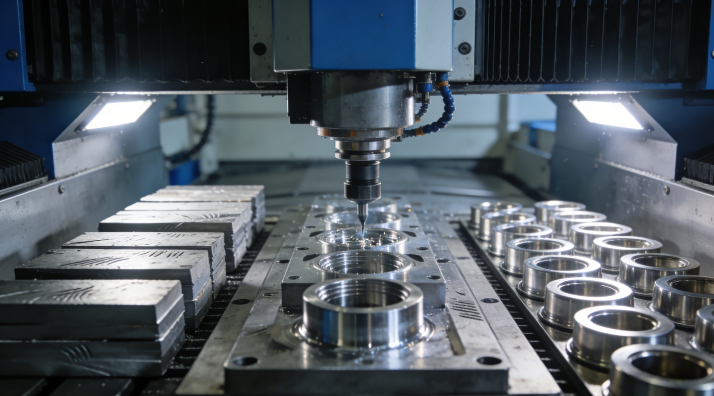
Imagine a solid aluminum cylinder destined to become a precision shaft. A lathe rotates this workpiece while cutting tools progressively remove material, creating the exact diameter, surface finish, and features required. The process demands attention to three critical parameters: cutting speed, feed rate, and depth of cut. These cutting conditions determine everything from material removal rate to final surface quality.
What makes this transformation remarkable is the precision achievable. Modern machining of parts routinely holds tolerances measured in thousandths of an inch, ensuring components fit together perfectly in assemblies ranging from automotive engines to medical devices.
Core Machining Processes and When to Use Each
Now that you understand what machining means, the next logical question is: which machining operations should you use for your specific project? The answer depends entirely on your part's geometry, material, and precision requirements. Let's break down the primary machining types so you can make informed decisions.
CNC Milling and Its Multi-Axis Capabilities
Picture a rotating cutting tool approaching a stationary workpiece from multiple angles. That's milling machining in action. Unlike turning, where the workpiece spins, milling keeps the material fixed while the tool to cut metal moves along programmed paths. This fundamental difference unlocks incredible geometric flexibility.
What makes precision cnc milling particularly powerful? Multi-axis capabilities. While basic 3-axis mills move along X, Y, and Z coordinates, advanced 4-axis and 5-axis machines add rotational movements. This means your cutting metal machine can approach the workpiece from virtually any angle, creating undercuts, compound curves, and intricate features that would otherwise require multiple setups.
Consider these common milling applications:
- Complex enclosures: Pockets, slots, and detailed surface profiles
- Custom gears: Precise tooth geometry and spacing
- Aerospace components: Lightweight structural parts with irregular contours
- Prototypes: Rapid iteration of consumer product designs
According to Komacut, CNC milling excels when handling materials that are challenging to turn, such as hardened steels and exotic alloys. The rotating cutter distributes heat more effectively than stationary turning tools, reducing thermal damage to difficult materials.
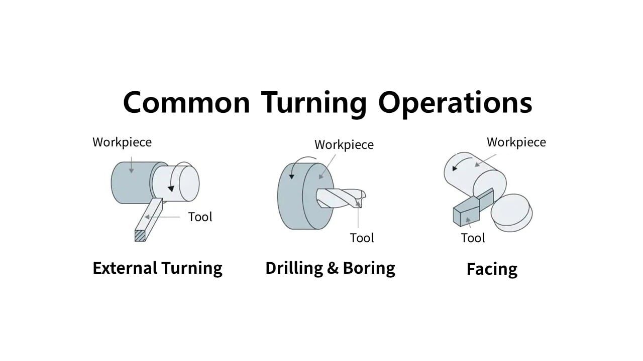
Turning Operations for Cylindrical Precision
When your part features cylindrical or symmetrical geometry, turning becomes the go-to process. Here, the workpiece rotates while a stationary cutting tool shapes it along the axis. Think shafts, bushings, rings, and flanges—any component with rotational symmetry.
The efficiency advantage is substantial. Because the workpiece continuously rotates past the cutting edge, material removal happens rapidly and consistently. For high-volume production of cylindrical parts, turning operations typically outperform milling in both speed and cost-effectiveness.
However, turning has inherent limitations. The stationary tool can only shape the rotating workpiece along its axis, making complex geometries difficult or impossible to achieve. If your design includes features that break rotational symmetry, you'll likely need milling operations or a combination approach.
Modern mill-turn centers address this limitation by integrating both capabilities into a single setup. These multitasking machines coordinate rotating tools with workpiece rotation, enabling comprehensive part manufacturing without multiple machine transfers.
Specialized Processes Including Drilling, Grinding, and EDM
Beyond milling and turning, several specialized machining operations handle specific tasks that primary processes cannot efficiently accomplish.
Drilling creates cylindrical holes using rotating drill bits. While seemingly simple, precision drilling demands careful attention to depth control, concentricity, and surface finish inside the hole. Sawing machining handles stock separation and rough cutting, typically as a preparatory step before primary operations.
Grinding achieves surface finishes and tolerances beyond what cutting tools can deliver. Using abrasive wheels, grinding removes minute amounts of material to create mirror-like surfaces and dimensional accuracy measured in microns. It's essential for hardened components where conventional cutting would damage tools.
Electrical Discharge Machining (EDM) represents a fundamentally different approach. Instead of mechanical cutting, EDM uses electrical sparks to erode material. This makes it ideal for extremely hard materials and intricate internal features that no conventional tool to cut metal can reach.
Understanding these shaping manufacturing processes helps you recognize when specialized operations add value to your project. The table below summarizes key distinctions:
| Process Type | Best Applications | Achievable Tolerances | Material Suitability |
|---|---|---|---|
| CNC Milling | Complex geometries, irregular contours, pockets, slots | ±0.001" to ±0.005" (±0.025 to ±0.127 mm) | Aluminum, steel, titanium, plastics, composites |
| CNC Turning | Cylindrical parts, shafts, bushings, flanges, rings | ±0.001" to ±0.005" (±0.025 to ±0.127 mm) | Most metals and plastics with rotational symmetry |
| Drilling | Hole creation, tapping, reaming | ±0.002" to ±0.008" (±0.05 to ±0.203 mm) | All machinable materials |
| Grinding | Fine surface finish, hardened materials, tight tolerances | ±0.0001" to ±0.001" (±0.0025 to ±0.025 mm) | Hardened steels, ceramics, carbides |
| EDM | Complex internal features, hardened materials, delicate parts | ±0.0002" to ±0.002" (±0.005 to ±0.05 mm) | Any electrically conductive material |
Choosing the right machining operations often involves combining multiple processes. A part might start on a lathe for cylindrical features, move to a mill for additional geometry, and finish with grinding for critical surfaces. Understanding how these processes complement each other positions you to optimize both quality and cost in your machining of parts projects.
Material Selection Strategies for Machined Components
Sounds complex? Choosing the right material for your machined metal parts can feel overwhelming when you consider the dozens of options available. Yet this decision fundamentally shapes everything from cutting parameters to final part performance. The material you select determines tool wear rates, achievable surface finishes, and ultimately, project costs. Let's break down the key categories so you can match materials to your specific application requirements.
Metals and Alloys for Structural Applications
When strength, durability, and thermal resistance matter, metals remain the go-to choice for metal machining projects. Each metal family brings distinct advantages and machining characteristics that influence your process planning.
- Aluminum alloys: Lightweight with excellent machinability ratings often exceeding 200%. Ideal for aerospace, automotive, and consumer electronics where weight reduction matters.
- Carbon and alloy steels: Offer superior strength and wear resistance. Machinability varies widely from 40% for bearing steels to 170% for free-cutting grades like 12L14.
- Stainless steels: Provide corrosion resistance but present machining challenges. Common grades like 316 rate around 36% machinability, while 303 exceeds 60%.
- Titanium alloys: Exceptional strength-to-weight ratio with Ti-6Al-4V rating only 20% machinability. Reserved for aerospace and medical applications where performance justifies cost.
- Brass and copper alloys: Outstanding machinability (often 300%+) with natural corrosion resistance. Perfect for electrical components, fittings, and decorative hardware.
How does steel machining differ from aluminum in practice? The contrast is dramatic. Aluminum's softness allows cutting speeds three to four times faster than steel, with significantly reduced tool wear. According to The Machining Doctor, machinability ratings directly correlate with cutting speeds—a material rating 200% can typically be cut at double the speed of the 100% reference steel.
Steel machining demands more robust tooling, slower feeds, and careful attention to heat management. The payoff comes in mechanical properties: steel components handle higher loads, resist wear better, and maintain dimensional stability under thermal stress. For precision machined metal parts requiring both strength and tight tolerances, steel often delivers the best value despite higher machining costs.
Engineering Plastics and Composite Materials
Not every application requires metal. Engineering plastics and composites offer compelling advantages for specific use cases, particularly where weight reduction, chemical resistance, or electrical insulation matters.
CNC machining metal alternatives include:
- Acetal (Delrin): Excellent dimensional stability and low friction. Ideal for gears, bearings, and precision mechanical components.
- PEEK: High-performance thermoplastic with outstanding chemical resistance and temperature tolerance up to 250°C. Common in medical and aerospace applications.
- Nylon: Good balance of strength, flexibility, and cost-effectiveness. Used extensively for bushings and wear components.
- PTFE (Teflon): Lowest friction coefficient of any solid material. Essential for seals, gaskets, and non-stick surfaces.
- Carbon fiber composites: Exceptional stiffness-to-weight ratio. Requires specialized tooling due to abrasive fiber content.
Composites represent the frontier of material innovation in machining metalworking shops that have expanded their capabilities. As noted by Machining Concepts, these advanced materials harness the best attributes of their components, resulting in engineered solutions that are both robust and surprisingly lightweight. However, they demand specialized cutting strategies—standard metal tools wear rapidly against abrasive fibers, and dust management becomes a safety concern.
Material Properties That Impact Machinability
Why do some materials cut like butter while others destroy tools within minutes? The answer lies in fundamental material properties that every machinist must understand.
Hardness creates a paradox in metal milling operations. Very hard materials cause rapid tool wear, but excessively soft materials behave "gummy," sticking to cutting edges and producing poor surface finishes. According to machinability research, intermediate hardness yields optimal results. This explains why annealed materials often machine better than their hardened counterparts.
Thermal conductivity determines how quickly heat dissipates from the cutting zone. Aluminum's high conductivity carries heat away efficiently, protecting both tool and workpiece. Titanium's poor thermal conductivity concentrates heat at the cutting edge, demanding reduced speeds and aggressive coolant application.
Chip formation characteristics directly impact surface finish and tool life. Ideal materials produce short, curly chips that clear easily from the cutting zone. Long, stringy chips wrap around tools, mar finished surfaces, and create safety hazards. Free-machining steels contain additives like lead or sulfur specifically to improve chip breakability.
When selecting materials for metal machined parts, consider these interconnected factors:
- Carbon content in steel: 0.3-0.5% provides optimal machinability. Lower creates gummy behavior; higher increases strength but reduces machinability.
- Alloying elements: Chromium, molybdenum, and nickel improve mechanical properties but typically decrease machinability.
- Heat treatment state: Annealed materials generally machine easier than hardened versions of the same alloy.
- Grain structure: Small, uniform grains cut cleaner than large, disordered structures.
Connecting material choice to end-use requirements completes the selection process. A medical implant demands biocompatible titanium despite machining challenges. An automotive bracket might use aluminum for weight savings or steel for cost efficiency. Consumer electronics housings often specify aluminum for its combination of machinability, appearance, and electromagnetic shielding.
Understanding these material dynamics positions you to have productive conversations with your machining partner. Rather than simply specifying "aluminum" or "steel," you can discuss specific alloys and tempers that balance performance requirements with manufacturing efficiency—the foundation for cost-effective precision machined metal parts.
Understanding Tolerances and Precision Standards
You've selected your material. You've identified the right machining process. Now comes a question that directly impacts both quality and cost: how tight do your tolerances really need to be? Understanding what is precision machining versus standard machining helps you avoid two costly mistakes—over-specifying tolerances that inflate costs unnecessarily, or under-specifying tolerances that compromise part function.
Here's the reality: the relationship between tolerance and manufacturing cost isn't linear—it's exponential. According to Modus Advanced, moving from rough machining tolerances to precision tolerances increases costs by approximately 4x, while ultra-precision tolerances can cost 24 times more than standard machining. Understanding where your precision machined part truly needs tight control versus where standard tolerances suffice transforms your approach to cost-effective manufacturing.
Standard vs Precision Tolerance Ranges
What tolerances can you realistically expect from different machining processes? Standard CNC machining tolerances of ±0.25 mm (±0.010") represent the baseline capability for most precision manufacturing operations. This tolerance level accommodates normal variations in machine tool accuracy, thermal effects, tool wear, and setup repeatability while maintaining economical production rates.
For applications requiring greater accuracy, precision machining techniques achieve significantly tighter results:
- Standard tolerances: ±0.13 mm (±0.005") for general-purpose components where fit isn't critical
- Precision tolerances: ±0.025 mm (±0.001") for assemblies requiring reliable interfacing
- High precision machining: ±0.0125 mm (±0.0005") for aerospace and medical applications
- Ultra-precision: ±0.005 mm (±0.0002") for specialized instruments and implants
According to HLH Rapid, only about 1% of parts require tolerances in the ±0.0002" to ±0.0005" range. Often, it's just certain features that genuinely need ±0.001" or tighter—not the entire component. This insight reveals a common optimization opportunity: apply tight tolerances selectively to critical features while allowing non-critical dimensions to remain at standard tolerances.
| Process | Standard Tolerance | Precision Tolerance | Relative Cost Impact |
|---|---|---|---|
| CNC Milling | ±0.13 mm (±0.005") | ±0.025 mm (±0.001") | 50-100% increase |
| CNC Turning | ±0.13 mm (±0.005") | ±0.025 mm (±0.001") | 50-100% increase |
| Grinding | ±0.025 mm (±0.001") | ±0.005 mm (±0.0002") | 100-200% increase |
| EDM | ±0.05 mm (±0.002") | ±0.013 mm (±0.0005") | 75-150% increase |
| Temperature-Controlled Machining | ±0.125 mm (±0.005") | ±0.05 mm (±0.002") | 25-50% increase |
Material properties also influence achievable tolerances. Aluminum alloys offer excellent machinability and relatively low thermal expansion, making them suitable for precision milling parts. Steel provides dimensional stability but requires attention to heat treatment effects. Titanium presents machining challenges that may limit practical tolerance achievement without specialized techniques.
Industry Standards and Certification Requirements
How do manufacturers communicate tolerance requirements consistently across global supply chains? International standards provide the framework. ISO 2768 establishes general tolerances for linear and angular dimensions, eliminating the need to specify tolerances for every single feature on a drawing.
The ISO 2768 standard divides tolerances into four classes:
- Fine (f): For precision machined components requiring close dimensional control
- Medium (m): The default for most CNC machined parts—typically around ±0.13 mm (±0.005")
- Coarse (c): For less critical applications where fit tolerance is generous
- Very coarse (v): For rough machining or non-functional dimensions
Beyond dimensional standards, quality management certifications ensure consistent manufacturing practices. ISO 9001:2015 certification demonstrates that a manufacturer maintains documented quality systems, process controls, and continuous improvement programs. For precision machined components destined for critical applications, this certification provides assurance that tolerance specifications will be met consistently across production runs.
Industry-specific certifications add additional requirements. AS9100 covers aerospace quality management, while IATF 16949 addresses automotive supply chain demands. These certifications require statistical process control, traceability documentation, and enhanced inspection protocols that support high-precision machining solutions.
The Cost-Tolerance Relationship
Why does high precision machining command premium pricing? The answer involves cascading requirements that affect every aspect of production.
Temperature variations represent one of the most significant factors. Machine tool structures expand and contract with temperature changes, affecting spindle position and part dimensions. Standard tolerance specifications accommodate typical shop temperature variations of ±3°C. Achieving precision tolerances often requires dedicated climate-controlled areas maintaining ±0.5°C—a substantial infrastructure investment.
Tool wear progression creates gradual dimensional changes during production runs. Standard tolerances accommodate normal tool wear while enabling economical tool life utilization. Tighter tolerances demand more frequent tool changes, increasing both tooling costs and machine downtime.
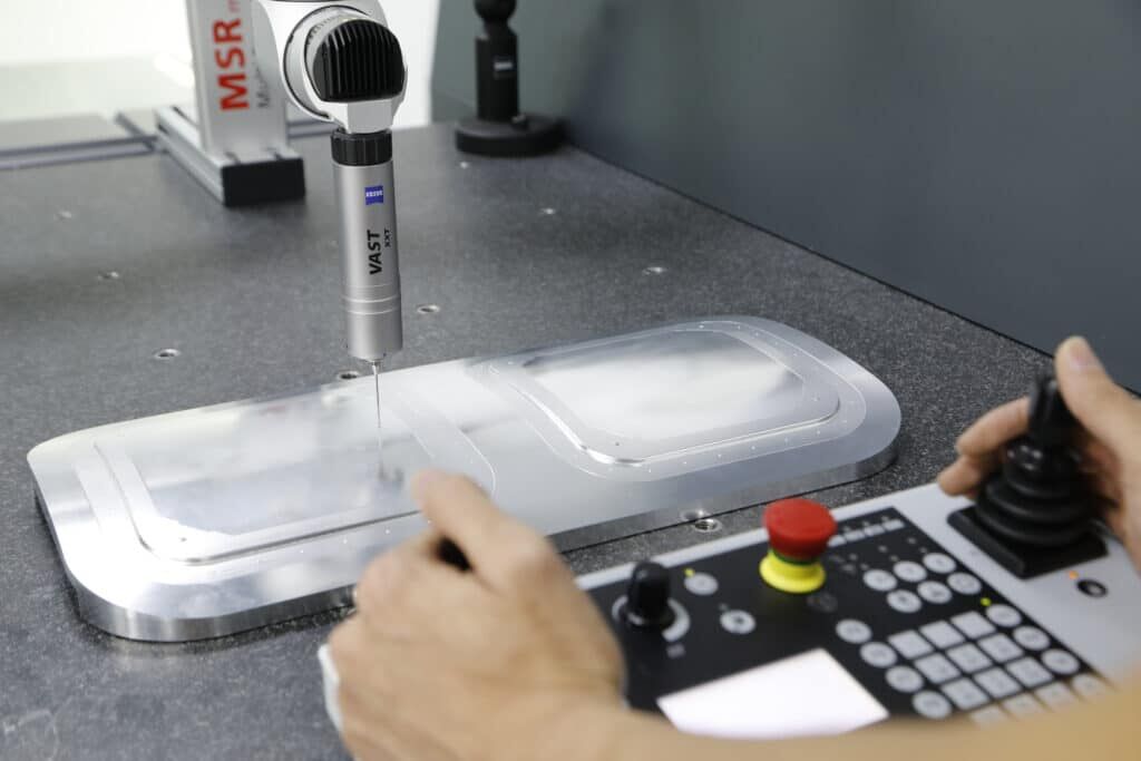
Inspection requirements escalate dramatically with tighter specifications. A precision machined part may require coordinate measuring machine (CMM) verification rather than simple go/no-go gauging. Complex geometric measurements take significantly longer than dimensional checks, and these differences compound across production quantities.
Consider these cost drivers that accumulate with tighter tolerances:
- Machine time: Slower cutting speeds and lighter cuts to maintain accuracy
- Setup time: More careful alignment and verification procedures
- Tooling: Premium cutting tools with tighter manufacturing tolerances
- Environment: Temperature and vibration control requirements
- Inspection: Comprehensive measurement protocols and documentation
- Scrap risk: Higher rejection rates when pushing process limits
When is high precision machining genuinely necessary? Critical applications include bearing surfaces where fit determines performance, sealing interfaces requiring specific compression, assembly interfaces with minimal clearance, and safety-critical components where dimensional variation affects function. For these applications, the precision premium delivers measurable value.
Conversely, specifying ±0.001" on a clearance hole that functions perfectly at ±0.010" wastes money without improving your product. Smart tolerance allocation—tight control where function demands it, standard tolerances elsewhere—optimizes both quality and cost in your machining of parts projects.
Design Guidelines That Reduce Cost and Improve Quality
You've selected the perfect material and specified appropriate tolerances. Now comes the design phase—where decisions made in CAD directly translate into dollars on your quote. Here's the reality many engineers discover too late: a seemingly minor design choice, like specifying an unnecessarily tight internal corner, can transform a straightforward machining operation into a complex, time-intensive process that doubles your lead time.
Design for manufacturability (DFM) principles bridge the gap between engineering intent and production reality. According to Modus Advanced, effective DFM implementation can reduce manufacturing costs by 15-40% and cut lead times by 25-60% compared to non-optimized designs. Let's explore the specific guidelines that deliver these savings.
Wall Thickness and Feature Accessibility Rules
Imagine your work piece spinning in a lathe or clamped on a mill table. Now picture the cutting tool approaching each feature. Can it physically reach every surface without collision? Will thin sections vibrate or deflect under cutting forces? These questions define the accessibility constraints that shape practical design.
Wall thickness directly impacts machining stability. During cutting, the tool exerts forces against the material. Thin walls lack the rigidity to resist these forces, leading to vibration, deflection, and dimensional inaccuracy. The thinner the wall, the slower the machining speed required to maintain quality—and slower speeds mean higher costs.
Follow these minimum wall thickness guidelines:
- Metals: 0.8 mm (0.03") minimum; 1.5 mm (0.06") recommended for stability
- Plastics: 1.5 mm (0.06") minimum due to lower rigidity
- Width-to-height ratio: Maintain 3:1 for unsupported walls to prevent deflection
- Deep pockets: Wall thickness should increase proportionally with depth
Tool reach considerations add another dimension. Standard end mills have length-to-diameter ratios of 3:1 to 4:1. Beyond these limits, tools become susceptible to deflection and breakage. A 10 mm diameter tool can reliably cut 30-40 mm deep; requesting 60 mm depth requires specialized long-reach tooling with corresponding cost and lead time implications.
Avoiding Common Design Pitfalls
Certain design features consistently drive up costs without adding functional value. Recognizing these pitfalls before finalizing your design prevents expensive revisions and production delays.
Sharp internal corners represent the most common—and costly—mistake. End mills are cylindrical, making true 90-degree internal corners physically impossible to machine. The tool leaves a radius equal to its own radius. Specifying sharp corners forces manufacturers to use progressively smaller tools, dramatically increasing cycle time.
According to Geomiq, adding an internal radius 30% larger than the cutting tool's radius mitigates tool wear and increases cutting speed. For example, if your cutting tool is 10 mm, design internal edges with a 13 mm radius. This simple adjustment can reduce programming time by 50-100%.
Deep pockets create multiple challenges for machining components. Chip evacuation becomes difficult, tools deflect under extended reach, and surface finish quality degrades. Standard practice limits cavity depth to 3-4 times the tool diameter. Depths exceeding 6 times the diameter require specialized tooling and significantly slower feed rates.
Knife edges—where two surfaces meet at acute angles—create fragile features prone to damage during machining and handling. Add small outside fillets of 0.13-0.38 mm (0.005-0.015") to eliminate knife edges and improve part durability.
Design for Manufacturability Principles
Beyond avoiding individual pitfalls, systematic DFM thinking transforms how you approach basic machining design decisions. Every feature should earn its complexity by serving a functional purpose.
The 40% material removal threshold provides a useful economic guideline. When your design requires removing more than 40% of the starting stock material, you're likely paying substantial costs for chips going into the scrap bin rather than functional geometry. Beyond this threshold, consider whether alternative starting shapes (castings, extrusions, forgings) or additive manufacturing might prove more economical.
This rule applies most strongly when:
- Raw material costs are high (titanium, copper alloys, specialty steels)
- Part geometry features large internal cavities or extensive pocket milling
- Production volumes justify tooling investments for alternative processes
- Lead time pressures don't favor near-net-shape starting materials
Follow this sequential approach to optimize your designs for machine parts manufacturing:
- Question every geometric feature: Does this curve, fillet, or complex surface serve a functional purpose, or is it purely aesthetic?
- Standardize hole sizes: Use common drill diameters (3 mm, 6 mm, 8 mm, 10 mm) and standard thread sizes (M6, M8, M10) to minimize tool changes.
- Maximize internal radii: Specify the largest radius your design can accommodate—larger tools cut faster and deflect less.
- Align features with machine axes: Parts machinable on 3-axis equipment cost 50-80% less than those requiring 5-axis positioning.
- Consolidate setups: Design features accessible from minimal orientations to reduce fixturing complexity.
- Specify realistic surface finishes: Standard machined finish (3.2 μm Ra) suffices for most applications; mirror finishes add 25-100% to machining time.
These machining concepts connect directly to your bottom line. According to manufacturing cost research from HMaking, replacing sharp corners with larger radii, standardizing hole sizes, and avoiding unnecessary surface curvature can reduce machining time by 15-50%, especially on complex housings, brackets, or structural components.
The most cost-effective approach to machining for manufacturing involves early collaboration with your machining partner. Share your design intent during development, not just completed drawings. Experienced manufacturers can identify optimization opportunities—where a slight radius increase or tolerance relaxation saves significant production time—while your design remains flexible enough to accommodate changes efficiently.
Machining Compared to Alternative Manufacturing Methods
You've optimized your design for manufacturability. But here's a question that could save—or cost—you thousands: is machining even the right process for your project? The answer isn't always obvious, and choosing incorrectly can mean overpaying for low-volume runs or missing cost-saving opportunities at scale.
Understanding when machining manufacturing makes sense versus when alternatives deliver better value transforms how you approach part manufacturing decisions. Each process excels within specific volume ranges, complexity requirements, and timeline constraints. Let's break down the quantitative comparisons that guide smart manufacturing choices.
Machining vs Injection Molding Decision Criteria
Picture two scenarios: you need 50 custom housings for a pilot program, or you need 50,000 identical housings for mass distribution. The manufacturing approach differs dramatically between these situations—and the economics explain why.
Injection molding delivers unmatched efficiency for high-volume production machining, but it carries a significant barrier to entry: tooling investment. Custom molds typically cost between $3,000 for simple geometries to over $100,000 for complex multi-cavity tools. According to Trustbridge, this upfront investment means injection molding only becomes economical when production volumes justify spreading tooling costs across thousands of parts.
The break-even calculation works like this:
- Machining: No tooling investment, but higher per-part costs ($20-200+ depending on complexity)
- Injection molding: $5,000-50,000+ tooling investment, but per-part costs drop to $0.50-5.00 at volume
- Break-even point: Typically 5,000-10,000 units, varying with part complexity and material
Beyond volume considerations, material requirements influence this decision significantly. Machine manufacturing handles metals, engineering plastics, and composites with equal capability. Injection molding works exclusively with thermoplastics and some thermosetting materials—eliminating it entirely when your application demands aluminum, steel, or titanium components.
Timeline pressures also favor machining for initial production. While injection mold fabrication requires weeks to months, CNC machining delivers functional parts within days. Many successful product launches use machined parts for initial market testing before investing in injection molding tooling once demand is validated.
When 3D Printing Complements or Replaces Machining
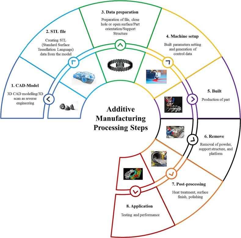
The rise of additive manufacturing has complicated the machine production decision tree—but not in the way many assume. Rather than competing directly, 3D printing and machining often serve complementary roles in the concept-to-production journey.
For prototyping and design validation, 3D printing offers compelling advantages. You can move from CAD file to physical part in hours rather than days, enabling rapid iteration during development. According to industry data from Trustbridge, leveraging 3D printing in the prototyping phase can reduce product development lead times by up to 75% compared to traditional methods.
However, 3D printing carries limitations that machining overcomes:
- Material properties: 3D printed parts exhibit anisotropic behavior—strength varies depending on print orientation. Machined parts from solid stock maintain consistent, isotropic mechanical properties.
- Surface finish: Layer lines inherent to additive processes require post-processing for smooth surfaces. Machining delivers superior finishes directly from the machine.
- Tolerances: Industrial CNC equipment achieves ±0.025 mm accuracy; most 3D printers operate at ±0.1 mm or looser.
- Material options: Machining works with virtually any metal, plastic, or composite. 3D printing material libraries remain more limited, particularly for metals.
The prototype-to-production transition often follows a predictable pattern. Teams use 3D printing for early concept models (1-5 units), transition to machining for functional prototypes and pilot runs (10-500 units), then evaluate injection molding or continued machining based on volume projections.
Small component manufacturing presents an interesting exception. Micro manufacturing applications involving intricate geometries impossible to machine—internal channels, lattice structures, organic shapes—may favor additive processes even at higher volumes. The geometric freedom of 3D printing creates parts that no cutting tool can reach.
Casting and Forging Alternatives
When volumes climb into thousands or millions of units, casting and forging enter the conversation as potential alternatives to pure machining approaches. These processes create near-net-shape parts that may require only minimal finishing machining.
Casting involves pouring molten metal into molds, offering several advantages for high-volume scenarios:
- Complex internal geometries achievable in a single operation
- Minimal material waste compared to machining from solid stock
- Scalability to millions of parts with consistent properties
- Broad material compatibility including aluminum, iron, steel, and bronze alloys
According to Wevolver, the main drawback of casting is the lead time for tooling, which can take several weeks. Sand casting offers lower tooling costs but rougher surfaces; die casting delivers excellent detail but requires substantial mold investments.
Forging applies force to shape metal while maintaining grain structure integrity. This process creates the strongest possible metal components—essential for critical applications like engine components, gears, and aerospace structures. However, forging costs run very high due to specialized machinery, skilled labor, and custom die requirements.
Many production programs combine processes strategically. A forging or casting creates the near-net-shape blank, then machining adds precision features, tight-tolerance surfaces, and fine details. This hybrid approach captures the efficiency of bulk forming while achieving the accuracy of subtractive manufacturing.
| Method | Ideal Volume Range | Typical Lead Time | Material Options | Best Applications |
|---|---|---|---|---|
| CNC Machining | 1 - 5,000 units | 1-15 days | All metals, plastics, composites | Prototypes, custom parts, precision components |
| 3D Printing | 1 - 20 units | 1-5 days | Limited metals, various polymers | Rapid prototyping, complex geometries, concept models |
| Injection Molding | 5,000+ units | 4-12 weeks (tooling) | Thermoplastics, some thermosets | High-volume plastic parts, consumer products |
| Die Casting | 10,000+ units | 8-16 weeks (tooling) | Aluminum, zinc, magnesium alloys | Complex metal housings, automotive components |
| Sand Casting | 100 - 10,000 units | 2-6 weeks | Iron, steel, bronze, aluminum | Large parts, complex internals, lower-volume metal |
| Forging | 1,000+ units | 6-12 weeks (tooling) | Steel, aluminum, titanium | High-strength structural components, load-bearing parts |
The decision framework crystallizes when you consider four interconnected factors:
- Quantity: Low volumes (under 500) almost always favor machining economics. High volumes (over 5,000) warrant tooling investments in molding or casting.
- Complexity: Intricate internal features may require casting or additive. External precision features favor machining.
- Material requirements: Metal parts with specific alloy requirements often eliminate injection molding. Strength-critical applications may demand forging.
- Timeline: Urgent needs favor machining's quick turnaround. Longer development cycles allow time for tooling investments that pay off at scale.
From concept to finished part, these decisions interconnect in a logical progression. Early development uses rapid prototyping for design validation. Pilot production leverages machining's flexibility without tooling commitments. Full-scale manufacturing evaluates all options based on validated volumes and specifications. Understanding this complete journey positions you to make manufacturing decisions that optimize cost, quality, and timing throughout your product lifecycle.
Industry-Specific Applications and Requirements
Here's something many engineers overlook: the same aluminum bracket machined to identical specifications can either pass or fail depending entirely on which industry it serves. Why? Because industrial machining requirements extend far beyond dimensional accuracy. Each sector layers additional demands—material traceability, process certifications, documentation protocols—that fundamentally shape how precision machining companies approach production.
Understanding these industry-specific requirements before you start your project prevents costly surprises. A part designed for automotive production faces different scrutiny than one destined for a medical device, even when tolerances appear similar on paper. Let's examine how aerospace, medical, and automotive sectors each bring unique demands to the machining of parts.
Aerospace and Defense Component Requirements
When a component's failure could bring down an aircraft, the stakes demand manufacturing standards beyond anything in typical industrial settings. Aerospace cnc machinist work operates under the most stringent quality requirements in manufacturing—and for good reason. Every feature, every dimension, every surface finish carries potential safety implications.
According to CNC Machines, the AS9100 certification forms the foundation for aerospace quality management. Building on ISO 9001, it adds aerospace-specific requirements for traceability and risk management that major OEMs require from their supply chain. Without AS9100, precision machining companies simply cannot access tier-one aerospace contracts.
Key certifications for aerospace machining include:
- AS9100: Core aerospace quality system covering documentation, traceability, and risk management
- ITAR Compliance: Required for defense-related components, regulating access to sensitive data and export controls
- NADCAP: Specialized accreditation for processes like heat treating, non-destructive testing, and surface treatments
- Customer-specific approvals: Programs like Boeing's D1-4426 for direct OEM relationships
Material requirements in aerospace applications push boundaries. Titanium alloys, Inconel, and other exotic superalloys demand specialized tooling, conservative cutting parameters, and extensive process validation. High precision machining services handling these materials must demonstrate not just capability, but documented repeatability across production runs.
Traceability requirements add another dimension. Every precision cnc part destined for flight must carry complete material certifications, processing records, and inspection documentation traceable to specific raw material lots. This paper trail enables root-cause analysis if components ever show field issues—critical for maintaining safety across thousands of aircraft.
Medical Device Manufacturing Standards
Imagine a component that will be implanted inside a human body for decades. The manufacturing standards for such parts extend into territories where typical industrial machining never ventures—biocompatibility, sterility, and patient-specific traceability become paramount concerns.
According to Process Sensing, organizations designing or producing medical devices should follow ISO 13485 standards, which align with FDA 21 CFR Part 820 requirements. This framework ensures quality management systems specifically address the unique risks associated with medical applications.
Medical micro machining presents unique challenges beyond standard precision work:
- Biocompatibility validation: Materials must demonstrate compatibility with human tissue through standardized testing protocols
- Surface finish criticality: Implant surfaces require specific roughness ranges to promote bone integration or prevent bacterial adhesion
- Cleaning validation: Manufacturing residues, cutting fluids, and contaminants must be completely removed before sterilization
- Lot traceability: Each component must be traceable to specific raw materials, processing dates, and inspection records
Environmental controls during medical device manufacturing often exceed aerospace requirements. Contact lens manufacturing, for example, requires monitoring temperature, humidity, oxygen levels, and differential pressure throughout production areas. Incorrect control of these parameters can affect final products, potentially creating patient risks including infections, allergies, or physical damage.
The documentation burden for precision cnc parts in medical applications reflects the regulatory reality. Every process parameter, inspection result, and deviation must be recorded and retained for the product's entire lifecycle—often decades for implantable devices. This traceability enables regulators to investigate issues and manufacturers to implement targeted corrections when problems emerge.
Automotive Production Demands
While aerospace focuses on individual part perfection and medical emphasizes patient safety, automotive manufacturing balances a different equation: high-volume precision with supply chain reliability. When you're producing thousands of components daily, consistency becomes the paramount concern.
IATF 16949 certification represents the automotive industry's quality standard, building on ISO 9001 with sector-specific requirements for production processes, supplier management, and continuous improvement. According to Advisera, this standard requires organizations to determine appropriate use of statistical tools—and Statistical Process Control (SPC) is the usual choice.
How does SPC ensure consistency? Rather than inspecting every part after production, control charts monitor the manufacturing process in real-time. Operators detect trends and changes before they lead to defective products or scrap. This shift from detection to prevention dramatically improves both quality and efficiency across high-volume production runs.
Automotive certification requirements include:
- IATF 16949: Automotive quality management system covering product development, production, and service
- PPAP (Production Part Approval Process): Formal documentation proving manufacturing capability before production release
- Statistical Process Control: Ongoing monitoring using control charts to maintain process stability
- Customer-specific requirements: Additional standards from OEMs like Ford, GM, or Toyota
Supply chain demands in automotive create unique pressures. Just-in-time manufacturing means suppliers must deliver precision cnc machining parts exactly when needed—not early, not late. Inventory buffers that worked in other industries become liabilities in automotive supply chains optimized for lean operations.
For manufacturers navigating these demands, certified partners make the difference between meeting production schedules and costly line stoppages. Shaoyi Metal Technology addresses these automotive supply chain needs with precision CNC machining services designed to scale seamlessly from rapid prototyping to mass production. Their IATF 16949-certified facility employs strict SPC protocols to deliver high-tolerance chassis assemblies and custom metal bushings with lead times as fast as one working day—the kind of responsiveness automotive production schedules demand.
The volume economics also differ substantially. While aerospace might order dozens of a specific precision cnc part annually, automotive programs consume thousands weekly. This volume intensity rewards process optimization, tooling investments, and the kind of production machining infrastructure that maintains quality across extended runs.
Understanding these industry-specific requirements transforms how you approach supplier selection. A machined parts manufacturer excelling in medical device work may lack automotive certifications—and vice versa. The next section explores how to evaluate potential partners against your specific industry requirements.
How to Evaluate and Select a Machining Partner
You've identified your industry requirements and understand what precision your project demands. Now comes a decision that will determine whether your machining of parts project succeeds or becomes a costly headache: choosing the right manufacturing partner. Here's what most procurement guides won't tell you—a certificate on the wall proves eligibility, not execution. The real question is whether that machined parts manufacturer actually uses their quality systems daily.
According to Zenithin Manufacturing, the renowned quality pioneer W. Edwards Deming advised ending the practice of awarding business based on price tag alone. Instead, minimize total cost—because a cheap part from a supplier who delivers late or goes out of business mid-production becomes the most expensive part you'll ever buy.
Quality Certifications That Matter
What certifications should you actually verify? The answer depends entirely on your application. A machined part destined for a consumer product faces different scrutiny than one entering an aerospace assembly or medical device.
- ISO 9001: The foundation for any serious machining parts manufacturers. Confirms documented quality management systems, process controls, and continuous improvement programs. Consider this your baseline requirement.
- AS9100: Essential for aerospace applications. Adds traceability, risk management, and configuration control requirements beyond ISO 9001.
- IATF 16949: Required for automotive supply chains. Emphasizes statistical process control, PPAP documentation, and supply chain management.
- ISO 13485: Mandatory for medical device manufacturing. Addresses biocompatibility, sterility, and patient-safety traceability.
- NADCAP: Specialized accreditation for aerospace processes including heat treating, welding, and non-destructive testing.
But here's the critical insight from industry auditors: a certificate only proves they have a system—your evaluation needs to prove they actually use it. According to TeleTec, reviewing internal audit reports from operations to management warrants that all levels of quality are met. Ask to see documentation trails for recent production batches. The speed and completeness of their response reveals how deeply embedded their quality culture really is.
Evaluating Technical Capabilities and Equipment
Tooling and equipment define what a machine shop can actually produce—and their limits. But counting machines isn't enough. As industry experts note, with the rise of reshoring, many new shops have brand-new equipment but lack the deep process knowledge and engineering talent to run it effectively.
Ask these revealing questions when evaluating cnc machining components capabilities:
- What equipment and software does the shop use, and when was it last updated?
- Can their engineering team demonstrate the CAM strategy for a complex part?
- What inspection equipment validates dimensional accuracy? (CMMs, optical comparators, surface finish testers)
- How do they handle prototype machined parts versus production volumes?
- What's their process for new part introduction (NPI)?
According to TeleTec's criteria, a quality precision machining manufacturer continuously looks for ways to improve and maintain their tooling while upgrading to more advanced technology. Every new generation of CNC equipment typically delivers greater precision, programmability, and speed than the generation before.
For machined components requiring tight tolerances, verify their inspection capabilities match your requirements. A shop quoting ±0.001" tolerances without appropriate measurement equipment cannot reliably deliver those specifications—regardless of their machine capabilities.
Communication and Project Management Factors
Technical capability means nothing if your supplier disappears when problems arise. The human element—responsiveness, transparency, and problem-solving ability—often determines project success more than equipment specifications.
Watch for this red flag during evaluations: the salesperson answers every technical question while engineering and quality managers remain silent. According to audit experts, you need to assess the capabilities of the people you'll actually work with. Ask engineers directly about their approach to challenging features. Their comfort level reveals organizational depth.
Evaluate these communication factors:
- Response time: How quickly do they acknowledge inquiries and provide quotes?
- Transparency: Will they discuss failure rates and improvement objectives openly?
- Design support: Do they offer DFM feedback during quoting, or just prices?
- Problem escalation: Who handles issues when they arise, and how quickly?
- Proactive communication: Do they notify you of potential delays before deadlines pass?
According to UPTIVE Advanced Manufacturing, the right partner should offer additional support for prototyping, DFM, and design consultations—making the design process smoother and long-term production more cost-effective. This collaborative approach transforms the traditional customer-supplier dynamic into a genuine partnership.
For scaling from prototype machined parts to production volumes, verify their capacity planning approach. A shop that excels at quick-turn prototypes may lack the infrastructure for sustained production runs. Conversely, high-volume production specialists may not prioritize small-batch flexibility. Match their strengths to your actual needs across the project lifecycle.
The proof is in the execution, not the certification. Ask to see complete documentation trails for random production batches—the smoothness and speed of their response tells you everything about how deeply embedded their quality system really is.
With your machining partner evaluation complete, the final piece of the puzzle involves understanding what drives the costs you'll see on quotes—and how your decisions influence final pricing.
Understanding What Drives Machining Costs
You've evaluated potential partners and understand quality requirements. Now comes the question on everyone's mind: why does this machined part cost what it does? Unlike off-the-shelf components with transparent pricing, custom machining of parts involves interconnected cost factors that aren't immediately obvious—and understanding them gives you real leverage to optimize your spending.
According to RapidDirect, the total cost formula breaks down simply: Total Cost = Material Cost + (Machining Time × Machine Rate) + Setup Cost + Finishing Cost. But within each element lies complexity that separates informed buyers from those facing sticker shock. Let's decode what actually drives your quotes.
Material Costs and Waste Considerations
The raw stock you specify directly impacts your bottom line—but not just through material prices. Modern machining technology removes material to create your part, meaning you're paying for chips that end up in the recycling bin.
Material cost factors include:
- Base material pricing: Steel and aluminum remain the most economical options due to abundance. Titanium and specialty alloys command significant premiums due to refinement complexity.
- Stock sizing: Parts fitting standard bar or plate dimensions cost less than those requiring oversized billets. According to Protolabs, designing around common stock sizes avoids unnecessary scrap.
- Material waste ratio: When your design removes 60% of the starting stock, you're paying material costs for geometry that never becomes part of your product.
- Machinability impact: Difficult materials require slower cutting speeds and cause faster tool wear—both adding hidden costs beyond raw material prices.
Consider machining metal parts from aluminum versus titanium. Aluminum's low cost per kilogram combines with excellent machinability, enabling fast cutting speeds and extended tool life. Titanium costs more per kilogram and demands dramatically slower feeds, specialized tooling, and aggressive coolant strategies. The machined part price reflects both factors compounded.
Machine Time and Complexity Factors
Here's where design decisions translate directly into dollars. Every feature on your part requires tool movements, and those movements consume machine time at rates ranging from modest for basic 3-axis mills to premium for 5-axis equipment.
According to HPPI, the more complex a part is, the higher the manufacturing cost. Complex parts often need advanced machinery, more machining time, multiple setups, additional resources, and thorough inspections—all of which increase costs.
Features that increase cycle time include:
- Deep pockets: Require multiple passes and slower feeds to manage chip evacuation
- Thin walls: Demand reduced cutting forces, extending machining duration
- Tight internal radii: Force progressively smaller tools running at slower speeds
- Tight tolerances: Require lighter finishing passes and potentially secondary operations
- Complex contours: Increase toolpath length and may require 5-axis positioning
Small parts machining presents an interesting paradox. While material costs drop with size, handling complexity and precision requirements can actually increase per-part machining time. Micro-features demand specialized tooling and careful process control that offset any material savings.
Remember the design guidelines from earlier? They connect directly here. Replacing sharp internal corners with generous radii lets machinists use larger, faster-cutting tools. Relaxing tolerances where function allows eliminates slow finishing passes. Every DFM improvement translates into reduced machine time—and lower quotes.
Setup, Tooling, and Volume Economics
Fixed costs represent the foundational expenses incurred regardless of how many parts you order. According to HPPI, as the number of machined parts increases, the fixed cost per unit decreases, offering greater cost efficiency for larger orders.
Fixed cost elements include:
- CAM programming: Creating toolpaths and machining strategies for your specific geometry
- Fixture preparation: Designing and building workholding to secure your part during cutting
- Machine setup: Loading tools, establishing coordinates, and running first-article verification
- First-article inspection: Comprehensive measurement before production release
The math reveals why prototypes carry premium per-part pricing. According to RapidDirect, a $300 setup fee adds $300 to a single-piece order but only $3 per part in a 100-piece batch. This fixed-cost dilution explains the dramatic price breaks as quantities increase.
| Cost Factor | Impact Level | Optimization Strategy |
|---|---|---|
| Raw Material | Medium to High | Select machinable alloys; design around standard stock sizes |
| Machine Time | High | Simplify geometry; increase radii; relax non-critical tolerances |
| Setup & Programming | High (low volume) / Low (high volume) | Consolidate setups; increase order quantities |
| Tooling Wear | Medium | Choose materials with better machinability; avoid abrasive composites |
| Post-Processing | Variable | Specify only necessary finishes; limit tight-tolerance features |
| Inspection | Low to Medium | Use general tolerances where possible; minimize CMM requirements |
When does production machining become more economical? The inflection point varies by part complexity, but precision parts machining typically shows significant per-unit cost reductions between 50-500 pieces. Beyond this range, tooling amortization, optimized fixturing, and process refinement compound to deliver increasingly favorable economics.
According to industry research, increasing production from one to five units can halve the unit price. Ordering in very large quantities—over 1,000 parts—can reduce the unit price by five to ten times compared to single-piece pricing.
The takeaway? Up to 80% of manufacturing cost is locked in during design, according to RapidDirect's analysis. Simplifying geometry and avoiding difficult-to-machine features during development offers the fastest path to reducing CNC pricing. Smart design choices made early compound into substantial savings across every production run.
Putting Machining Knowledge Into Practice
You've journeyed through the complete landscape of machining—from foundational definitions to cost optimization strategies. Now comes the critical question: how do you transform this knowledge into successful machined products? Whether you're launching your first project or refining an established program, the principles remain consistent. Success in general machining comes from applying the right process, material, and partner to your specific requirements.
Up to 80% of manufacturing cost is locked in during design. The decisions you make before cutting begins—material selection, tolerance specification, feature geometry—determine whether your project delivers value or drains budget.
Key Takeaways for Successful Machined Parts
Throughout this guide, several principles emerged as critical success factors for mechanical machining projects. These aren't theoretical concepts—they're practical guidelines that separate smooth-running programs from costly headaches.
- Match process to geometry: Turning excels for cylindrical parts; milling handles complex contours. Choosing correctly from the start prevents expensive workarounds.
- Specify tolerances strategically: Apply tight tolerances only where function demands. Each precision level beyond standard adds exponential cost without proportional benefit.
- Design for manufacturability: Generous internal radii, standard hole sizes, and accessible features reduce cycle time and improve quality simultaneously.
- Select materials thoughtfully: Balance mechanical requirements against machinability. The cheapest raw material often isn't the most economical finished part.
- Verify certifications for your industry: ISO 9001 provides baseline assurance; AS9100, IATF 16949, or ISO 13485 address sector-specific requirements that generic shops cannot meet.
- Consider volume economics: Setup costs amortize across quantities. What seems expensive at prototype volumes often becomes highly competitive at production scale.
The machining world continues evolving. According to industry analysis, manufacturers integrating AI-driven maintenance, lean methodologies, and real-time analytics are achieving shorter lead times and more consistent production cycles. Staying informed about these developments positions you to leverage advancing capabilities in your projects.
Moving Forward with Your Machining Project
Where you stand in your project journey determines your next steps. Here's a practical roadmap based on your current situation:
- Concept stage: Focus on DFM principles during initial design. Engage potential manufacturing partners early—their input prevents costly redesigns later.
- Prototype phase: Validate form, fit, and function before committing to production tooling. Use machining's flexibility to iterate quickly without mold investments.
- Production planning: Evaluate volume projections honestly. Determine whether machining remains optimal or whether casting, molding, or hybrid approaches deliver better economics at scale.
- Supplier selection: Audit capabilities against your specific requirements. Certifications matter, but documented execution matters more.
- Ongoing production: Monitor quality trends through SPC data. Build relationships that enable continuous improvement rather than transactional exchanges.
For readers tackling automotive or precision machining projects, the path forward benefits from working with partners who understand sector-specific demands. Shaoyi Metal Technology exemplifies this approach—their IATF 16949-certified facility employs strict Statistical Process Control to deliver high-tolerance components with lead times as fast as one working day. This combination of certification, capability, and responsiveness enables seamless scaling from rapid prototyping through mass production.
Micro machining applications and specialized world machining requirements demand similar attention to partner capabilities. The principles remain consistent: verify that technical equipment, quality systems, and communication practices align with your project's complexity and industry requirements.
The knowledge you've gained positions you to approach machining projects with confidence. You understand the processes, recognize cost drivers, and know what questions to ask potential partners. That foundation—built on education rather than sales pressure—serves you whether you're ordering ten prototype parts or planning ten thousand production units. The machining of parts succeeds when informed decisions guide every step from design through delivery.
Frequently Asked Questions About Machining of Parts
1. How much does it cost to have parts machined?
CNC machining costs typically range from $50 to $150 per hour depending on equipment complexity and precision requirements. Total part cost combines material expenses, machine time, setup fees, and finishing operations. For prototypes, setup costs significantly impact per-unit pricing, but these fixed costs amortize across larger orders—increasing from one to five units can halve the unit price, while orders over 1,000 parts may reduce costs by five to ten times compared to single-piece pricing.
2. What does machining parts mean?
Machining parts refers to the subtractive manufacturing process where cutting tools systematically remove material from raw stock to create components with precise dimensions and smooth surface finishes. Unlike additive manufacturing that builds layer by layer, machining starts with more material than needed and removes everything that isn't part of the final design. This process includes operations like CNC milling, turning, drilling, and grinding to achieve tight tolerances.
3. What is the difference between CNC milling and turning?
CNC milling uses a rotating cutting tool that moves along programmed paths while the workpiece remains stationary, making it ideal for complex geometries, pockets, and irregular contours. CNC turning rotates the workpiece while a stationary tool shapes it along the axis, excelling at cylindrical parts like shafts and bushings. Milling offers greater geometric flexibility with multi-axis capabilities, while turning provides faster material removal for rotationally symmetric components.
4. How do I choose the right material for machined components?
Material selection balances mechanical requirements, machinability, and cost. Aluminum offers excellent machinability with cutting speeds three to four times faster than steel, ideal for weight-sensitive applications. Steel provides superior strength and wear resistance but requires slower feeds. Consider hardness, thermal conductivity, and chip formation characteristics—materials with intermediate hardness and good thermal conductivity typically machine more efficiently and cost-effectively.
5. What certifications should a machining partner have?
Essential certifications depend on your industry. ISO 9001 serves as the baseline quality management standard for all serious manufacturers. Aerospace applications require AS9100 certification for traceability and risk management. Automotive supply chains demand IATF 16949 with Statistical Process Control protocols. Medical device manufacturing needs ISO 13485 for biocompatibility and patient-safety traceability. Verify that partners actively use their quality systems rather than just displaying certificates.