 Small batches, high standards. Our rapid prototyping service makes validation faster and easier —

CNC Mechanical Systems Decoded: From G-Code To Precision Motion
What CNC Mechanical Systems Really Mean for Modern Manufacturing
When you hear the term "CNC," you might immediately think of computers and code. But here's the reality: the computer is only half the story. So what is CNC from a mechanical engineering perspective? CNC stands for "computer numerical control," yet the true magic happens when those digital commands transform into precise physical movements through carefully engineered mechanical systems.
Think of it this way. The computer acts as the brain, processing G-code instructions and calculating exact coordinates. However, it's the mechanical components—spindles, ball screws, linear guides, and servo motors—that actually touch the material and shape it into finished parts. Understanding c.n.c meaning from this dual perspective separates skilled practitioners from casual operators.
The Mechanical Heart of Automated Manufacturing
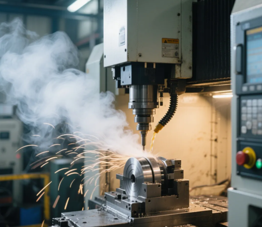
A CNC mechanical system is essentially a precisely orchestrated assembly of motion-control components working in concert. Unlike manual machining, where an operator's hands guide the cutting tool, a CNC system relies on mechanical components to execute movements with micron-level accuracy. These systems must translate electrical signals from the controller into smooth, controlled physical motion—all while withstanding significant cutting forces and thermal variations.
What does this mean practically? Every time a CNC mill cuts aluminum or a CNC lathe turns steel, the mechanical system handles forces that would challenge even experienced machinists. The spindle must maintain consistent speed under varying loads. Ball screws must convert rotary motor movement into linear travel without introducing errors. Linear guides must support the cutting head while allowing frictionless motion across the work envelope.
Beyond the Computer: Where Digital Commands Meet Physical Precision
So cnc what does it mean when we talk about bridging digital and physical worlds? Consider a simple operation: the controller sends a command to move the X-axis 10 millimeters at 500 millimeters per minute. That single instruction triggers a cascade of mechanical events. The servo motor receives an electrical pulse, its rotor spins a calculated number of revolutions, the ball screw converts that rotation into linear displacement, and the linear guide ensures the movement stays perfectly straight.
Operators who understand only the programming side often struggle to diagnose why their parts don't meet specifications. Those who grasp the mechanical fundamentals can identify whether the problem lies in backlash, thermal expansion, or bearing wear—and fix it before scrapping expensive material.
This is precisely what separates a CNC system from simple automation. The mechanical precision built into every component determines whether your finished parts hold tight tolerances or fall outside specification. According to industry standards, CNC machines typically achieve tolerances of approximately ±0.005 inches (0.127 mm)—roughly twice the width of a human hair—but achieving this requires mechanical components working in perfect harmony.
Understanding what is cnc system architecture from this mechanical perspective gives you a diagnostic advantage. When surface finish deteriorates, you'll know to check spindle bearings. When dimensions drift over a production run, you'll investigate thermal compensation. When parts show chatter marks, you'll examine rigidity throughout the mechanical chain.
Throughout this article, you'll discover exactly how each mechanical component contributes to machining precision—and how mastering these fundamentals will elevate your capabilities as a CNC practitioner.
Essential Mechanical Components Inside Every CNC Machine
Now that you understand how digital commands translate into physical motion, let's examine the mechanical components that make this translation possible. Whether you're operating a cnc mill, cnc lathe, or multi-axis machining center, the same fundamental components work together to achieve precision. Understanding these elements helps you optimize performance, troubleshoot issues, and appreciate why some cnc machines outperform others.
Every cnc machine relies on five core mechanical systems: spindles, ball screws, linear guides, servo motors, and bearings. Each plays a distinct role, and weaknesses in any component limit overall machine capability. Think of these as the essential organs of your machine—each must function properly for the whole system to thrive.
Spindles and Ball Screws: The Precision Duo
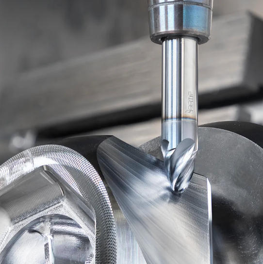
The spindle is arguably the most critical component in milling machines and metal lathes. It holds and rotates the cutting tool (in mills) or the workpiece (in lathes), directly influencing surface finish, material removal rates, and achievable tolerances.
Spindles come in several configurations:
- Belt-driven spindles: Common in entry-level machines, offering 2,000–8,000 RPM with moderate torque. Cost-effective but introduce slight vibration through belt transmission.
- Direct-drive spindles: Motor connects directly to the spindle shaft, eliminating belt-related vibration. Typical speeds range from 6,000–15,000 RPM with excellent torque characteristics.
- Integral motor spindles: The motor rotor is built into the spindle shaft itself. These achieve 20,000–60,000+ RPM, ideal for high-speed machining parts in aluminum and composites.
Torque matters as much as speed. A spindle rated at 40,000 RPM won't help if it lacks torque for heavy cuts in steel. High-end machines balance both—delivering sufficient torque at lower speeds for roughing while maintaining high speeds for finishing operations.
Ball screws convert the rotary motion from servo motors into the linear motion that moves your cutting tool or workpiece. Unlike traditional lead screws that rely on sliding contact, ball screws use recirculating ball bearings to roll along helical grooves. According to Anaheim Automation's technical documentation, this design achieves efficiency ratings exceeding 90%, compared to roughly 40% for sliding contact screws.
Why does this matter for machining parts? Higher efficiency means less heat generation, reduced wear, and more precise positioning. The balls eliminate backlash—that frustrating lost motion when reversing direction—which directly impacts dimensional accuracy. Premium ball screws achieve lead accuracy grades from C0 to C10, with C0 representing the highest precision suitable for demanding CNC applications.
Linear Motion Systems That Define Accuracy
While ball screws handle the driving force, linear guides ensure that motion stays perfectly straight. These guides support the moving components of your cnc machine—the spindle head, worktable, or carriage—while allowing smooth, friction-free travel.
Two primary types dominate modern CNC equipment:
- Linear ball guides (recirculating): Ball bearings roll between the rail and carriage, providing low friction and high load capacity. They're the standard choice for most cnc mills and machining centers.
- Roller guides: Use cylindrical rollers instead of balls, offering higher rigidity and load capacity. Preferred for heavy-duty metal lathes and large gantry machines where cutting forces are substantial.
The rigidity of your linear guide system directly impacts chatter resistance. Stiffer guides allow more aggressive cutting parameters without vibration-induced surface defects. As noted in Protolabs' analysis, the machine bed and frame work together with linear guides to absorb vibrations, ensuring dimensional accuracy in finished parts.
Servo motors provide the precisely controlled rotational force that drives ball screws and other motion components. Unlike standard motors, servo motors incorporate feedback systems—typically encoders or resolvers—that constantly report position to the cnc controller. This closed-loop system enables positioning accuracy measured in microns.
Modern servo motors achieve positioning accuracy of 2–5 micrometers when paired with quality ball screws, according to comparative analysis from Leapion. Their responsiveness—how quickly they accelerate, decelerate, and change direction—affects both cycle time and surface finish quality during complex contouring operations.
Finally, bearings support rotating and moving components throughout the machine. Spindle bearings handle the extreme demands of high-speed rotation under cutting loads, while support bearings maintain ball screw alignment and reduce friction. Quality angular contact bearings in spindles can operate at speeds exceeding 20,000 RPM while maintaining the rigidity needed for precision machining.
| Component | Function | Entry-Level Specs | Mid-Range Specs | High-End Specs |
|---|---|---|---|---|
| Spindle | Rotates cutting tool or workpiece | Belt-driven, 2,000–8,000 RPM, 3–5 HP | Direct-drive, 8,000–15,000 RPM, 10–15 HP | Integral motor, 20,000–40,000+ RPM, 15–30 HP |
| Ball Screw | Converts rotary to linear motion | Rolled, C7–C10 accuracy, 90% efficiency | Ground, C5–C7 accuracy, 92% efficiency | Precision ground, C0–C3 accuracy, 95%+ efficiency |
| Linear Guides | Supports and guides linear motion | Ball guides, standard preload | Ball guides, medium preload, higher rigidity | Roller guides, high preload, maximum rigidity |
| Servo Motors | Provides controlled rotational force | 1,000–2,000 pulse encoder, 1–2 kW | 4,000–8,000 pulse encoder, 2–5 kW | 17-bit+ absolute encoder, 5–15 kW |
| Bearings (Spindle) | Supports high-speed rotation | Standard precision, ABEC-5 | High precision, ABEC-7 | Ultra-precision, ABEC-9, ceramic hybrid |
Notice how each component class scales together. A high-speed integral spindle paired with entry-level ball screws creates a bottleneck—the cnc tools can spin fast, but positioning won't match that capability. This is why understanding component interaction matters when evaluating cnc machine quality or planning upgrades.
The cnc controller orchestrates all these components, reading G-code and sending precisely timed signals to each servo motor. However, even the most sophisticated controller cannot compensate for worn bearings, contaminated linear guides, or degraded ball screw accuracy. Mechanical excellence remains the foundation of precision machining.
With these core components understood, you're ready to explore how different axis configurations multiply mechanical complexity—and why adding axes isn't always the answer to machining challenges.
Comparing 3-Axis to 5-Axis Machine Configurations
You've seen how spindles, ball screws, and linear guides form the mechanical foundation of CNC systems. But here's a question worth considering: what happens when you add rotary axes to that foundation? The answer involves more than expanded capability—it fundamentally changes the mechanical dynamics of the entire machine.
Understanding these differences matters because choosing between axis configurations isn't simply about what shapes you can cut. It's about mechanical trade-offs that affect rigidity, accuracy, maintenance burden, and ultimately, your finished part quality.
How Additional Axes Change Machine Mechanics
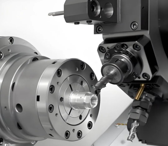
A 3-axis CNC machine operates along three linear directions: X, Y, and Z. These cnc milling machines move the cutting tool (or workpiece) horizontally, vertically, and in depth. The mechanical structure remains relatively straightforward—three sets of linear guides, three ball screws, and three servo motors working along perpendicular paths.
When you step up to 4-axis machines, you add rotational movement—typically the A-axis rotating around the X-axis. This requires integrating a rotary table or indexer into the mechanical system. Suddenly, your machine must handle both linear and rotational forces simultaneously, and the workpiece position changes relative to the spindle centerline during rotation.
Five-axis machines take this further by adding a second rotational axis, commonly the B-axis (rotating around Y) or C-axis (rotating around Z). According to AMFG's comprehensive guide, this configuration enables the cutting tool to approach the workpiece from virtually any angle—dramatically expanding geometric possibilities but multiplying mechanical complexity.
Consider what this means structurally. Each additional axis introduces:
- Additional bearings and rotary drives that must maintain precision under cutting loads
- Extended kinematic chains where small errors in one component accumulate through subsequent axes
- More potential deflection points as the workpiece sits further from the machine's rigid base
- Complex force vectors that change continuously during simultaneous multi-axis motion
The mechanical configurations for 5-axis machines vary significantly. Trunnion-style machines mount the workpiece on a tilting, rotating table. Head-tilting designs keep the workpiece stationary while the spindle head moves. Hybrid configurations combine both approaches. Each design offers different trade-offs between work envelope, accessibility, and mechanical rigidity.
Rigidity vs. Flexibility: The Multi-Axis Trade-off
Here's something experienced machinists understand intuitively: adding axes often means sacrificing rigidity. Why? Because rotary mechanisms introduce mechanical elements between the cutting tool and the machine's foundation—elements that can flex, vibrate, or deflect under load.
On a 3-axis cnc mill machine, the spindle connects to the machine column through linear guides with minimal compliance. Cutting forces transfer directly into the machine base. On a 5-axis machine with a trunnion table, those same forces must travel through rotary bearings, the trunnion structure, and then into the base. Each junction represents a potential point of deflection.
This doesn't mean 5-axis machines lack precision—far from it. As noted by BobCAD-CAM's technical analysis, industries like aerospace, medical, and mold making rely on 5-axis machining precisely because it delivers the required precision for complex surfaces. However, achieving that precision requires heavier, more rigid construction—which partly explains why capable 5-axis machines cost significantly more than their 3-axis counterparts.
The distinction between 3+2 machining (positional 5-axis) and full simultaneous 5-axis further illustrates this trade-off. In 3+2 machining, the rotary axes position the workpiece at a fixed angle, then the machine cuts using 3-axis movements. The rotary axes lock during cutting, maximizing rigidity. Full simultaneous 5-axis keeps all axes moving during cutting—enabling smoother surface finishes on contoured parts but demanding more from the mechanical system's ability to maintain accuracy during complex, coordinated motion.
| Configuration | Mechanical Complexity | Typical Applications | Accuracy Considerations | Maintenance Requirements |
|---|---|---|---|---|
| 3-Axis | Lowest—three linear motion systems only | Flat surfaces, 2.5D features, prismatic parts, prototyping | Highest inherent rigidity; accuracy limited by linear component quality | Simplest—fewer components to inspect, lubricate, and calibrate |
| 4-Axis | Moderate—adds rotary table or indexer | Parts requiring machining on multiple sides, cylindrical features, cnc turning applications | Rotary axis adds error source; indexing accuracy critical | Rotary bearings require periodic inspection; backlash checks needed |
| 5-Axis (3+2) | High—two rotary axes with positional locking | Complex parts machined at fixed angles, multi-sided features, angled holes | Rotary positioning accuracy matters; cutting occurs with axes locked for rigidity | Two rotary systems to maintain; simpler than full 5-axis operation |
| 5-Axis (Simultaneous) | Highest—continuous coordinated motion across all axes | Sculptured surfaces, aerospace components, medical implants, turbine blades | Requires RTCP/TCPC compensation; thermal stability critical; cumulative errors magnified | Most demanding—all components must maintain calibration; probing systems essential |
When do simpler configurations outperform complex ones? More often than you might expect. For prismatic parts with features on one or two faces, a rigid 3-axis machine often delivers better accuracy than a 5-axis machine attempting the same work. The additional mechanical elements in multi-axis cnc mills simply aren't needed—and their presence can actually degrade performance through added compliance and potential error sources.
Types of cnc machine configurations should match your actual production requirements. A shop producing thousands of flat aluminum plates doesn't benefit from 5-axis capability—but a manufacturer producing cnc milling components with compound curves and undercuts absolutely does. The key is matching mechanical capability to geometric complexity, not assuming more axes automatically means better results.
Understanding these mechanical realities helps you make informed decisions about equipment investments and recognize when a job truly requires multi-axis capability versus when simpler approaches deliver superior results. With axis configurations clarified, let's examine how the materials you cut interact with these mechanical systems—and why material selection directly influences machine performance.
How Materials Affect CNC Mechanical Performance
You've selected the right axis configuration for your project. Your spindle, ball screws, and linear guides are calibrated and ready. But here's a factor that changes everything: the material sitting on your worktable. Whether you're running cnc metal operations on titanium or operating a wood cnc machine for furniture components, material properties directly dictate how hard your mechanical systems must work—and how long they'll last.
Material selection isn't just a design decision. It's a mechanical decision that influences spindle load, feed rates, tool wear, and ultimately, the longevity of every moving component in your CNC system.
Material Properties That Challenge Machine Mechanics
Every material presents a unique combination of challenges for CNC mechanical systems. Hardness determines how much force your spindle must generate. Thermal conductivity affects where cutting heat accumulates. Work hardening tendencies can transform an easy cut into a battle against progressively tougher material.
Consider what happens during cnc cutting operations. The cutting tool engages the workpiece, generating friction and deformation. Some of that energy removes material as chips. The rest becomes heat—and where that heat goes depends entirely on material properties.
Aluminum, with its excellent thermal conductivity, dissipates heat efficiently into the workpiece and chips. Your spindle bearings and ball screws stay relatively cool. Titanium? According to Frigate's research on high-temperature machining, titanium and superalloys trap heat at the tool-workpiece interface because of poor thermal conductivity. That concentrated heat stresses your mechanical components, accelerates tool wear by 50-60%, and can cause thermal expansion that throws off dimensional accuracy.
Here's a breakdown of common material categories and their specific mechanical considerations:
- Aluminum alloys: Excellent machinability with high thermal conductivity. Challenges include chip welding and built-up edge on cutting tools. Allows aggressive feed rates and high spindle speeds, reducing cycle times while placing moderate loads on mechanical systems. Ideal for cnc machine metal operations requiring fast material removal.
- Carbon and alloy steels: Good machinability in most grades. Higher cutting forces than aluminum require increased spindle torque and more rigid setups. Some grades work harden during machining, progressively increasing cutting forces if parameters aren't optimized.
- Stainless steels: Austenitic grades (304, 316) work harden aggressively. Cutting forces can spike unexpectedly, stressing servo motors and ball screws. Requires rigid setups and consistent cutting engagement to prevent interrupted cuts that accelerate work hardening.
- Titanium alloys: Poor thermal conductivity concentrates heat at the cutting zone. According to Modus Advanced's material selection guide, titanium rates as "poor" for machinability, causing high tool wear and significant heat generation. Demands reduced speeds, specialized cooling, and expects 25-50% longer cycle times compared to steel.
- Engineering plastics: Variable machinability depending on composition. Elastic behavior can cause material to deflect rather than cut cleanly, affecting dimensional accuracy. Melting rather than cutting becomes a risk at excessive speeds. Lower cutting forces mean reduced mechanical stress but surface finish challenges.
- Composites (carbon fiber, fiberglass): Highly abrasive to cutting tools due to reinforcing fibers. Delamination risk requires specific cutting strategies and sharp tooling. Dust and fiber particles can contaminate linear guides and ball screws if not properly managed.
- Wood and wood products: Used extensively in wood cnc applications for furniture, cabinetry, and artistic work. Lower cutting forces than metals but generates fine dust requiring effective extraction. Moisture content affects dimensional stability during and after machining.
Matching Machine Capability to Material Demands
Understanding material properties helps you match your CNC mechanical systems to the demands you'll place on them. A machine optimized for high-speed aluminum metal cutting may struggle with the torque requirements of titanium. Conversely, a heavy-duty machine built for steel wastes capability on softer materials.
Spindle load varies dramatically based on material. Cutting aluminum at high speeds and feeds generates moderate torque but high RPM requirements—favoring integral motor spindles. Steel and titanium demand lower speeds but substantially higher torque, making direct-drive spindles with robust bearing systems essential. According to Tooling U-SME's analysis, materials exceeding 35 HRC hardness significantly increase tool wear and require specialized approaches.
Feed rates connect directly to mechanical wear. Aggressive feeds in hard materials generate cutting forces that stress ball screws, linear guides, and servo motors. Over time, these forces contribute to backlash development, bearing wear, and accuracy degradation. Shops running demanding materials continuously should expect shorter intervals between mechanical calibration and component replacement.
Heat generation affects more than just the cut. When machining titanium or superalloys, thermal expansion in the machine itself becomes a factor. As Frigate's research notes, structural rigidity in spindles, tool holders, and fixtures is directly affected by temperature fluctuations—leading to positioning variations during extended cutting operations. Advanced machines incorporate thermal compensation algorithms, but mechanical components still experience stress from these temperature cycles.
Material hardness also dictates cutting tool requirements, which indirectly affects mechanical systems. Harder materials require more rigid tool holding and workholding setups. Any compliance in the mechanical chain—loose linear guide preload, worn ball screw nuts, or marginal spindle bearings—manifests as chatter, poor surface finish, or dimensional drift when cutting challenging materials.
Matching material to machine isn't about limitations—it's about optimization. Understanding how your specific materials interact with CNC mechanical systems helps you set appropriate parameters, plan realistic maintenance intervals, and achieve consistent quality. With material considerations clarified, the next step connects these mechanical realities to the programming commands that drive them—revealing how your G-code choices directly impact machine health and performance.
Understanding How G-Code Commands Drive Mechanical Motion
You've explored the mechanical components that make CNC systems work and how different materials challenge those systems. But here's the critical connection many operators miss: every line of G-code you write directly commands those mechanical components. When you program CNC operations, you're not just telling the machine where to go—you're dictating exactly how servo motors accelerate, how ball screws translate rotation into travel, and how much stress your mechanical systems endure.
Understanding what is cnc programming from a mechanical perspective transforms you from someone who writes code to someone who orchestrates machine behavior. Let's break down how common G-code commands translate into physical motion and why certain programming decisions protect—or punish—your mechanical systems.
From Code to Motion: The Mechanical Translation
Every G-code command triggers a specific mechanical response. The CNC controller reads the instruction, calculates the required servo motor movements, and sends precisely timed electrical signals. Those signals drive the motors, which rotate ball screws, which move linear guides, which position your cutting tool. This chain happens thousands of times per second during complex operations.
Here's how the most common commands translate into mechanical action:
- G00 (Rapid Positioning): This command moves all axes simultaneously at maximum travel speed to reach specified coordinates. Your servo motors accelerate to their highest programmed velocity, and all three (or more) axes coordinate to complete the move at the same instant. According to How To Mechatronics' G-code reference, G00 is a non-cutting movement designed purely for repositioning. Mechanically, this means maximum acceleration stress on servo motors and ball screws, but no cutting load on the spindle.
- G01 (Linear Interpolation): Unlike rapid moves, G01 moves the tool in a straight line at a controlled feed rate you specify with the F parameter. The controller calculates intermediate points between start and end positions, sending thousands of micro-commands per second to maintain a perfectly straight path. Your ball screws must deliver smooth, consistent linear motion while the spindle handles cutting forces. This is where most actual machining happens.
- G02/G03 (Circular Interpolation): These commands create clockwise (G02) and counterclockwise (G03) arcs. The controller must coordinate two axes simultaneously, constantly calculating tangent points along the arc. Your servo motors receive continuously varying speed commands—one axis accelerates while the other decelerates to maintain the circular path. This places unique demands on positioning accuracy as both axes work in concert.
- G28 (Return to Home): This command sends the machine to its reference position, typically for tool changes or program completion. The mechanical system moves through any intermediate points you specify before reaching home. This prevents collisions while returning and gives linear guides and ball screws a known starting reference.
- M03/M04 (Spindle On): These M-codes activate spindle rotation clockwise or counterclockwise at the speed specified by the S parameter. Your spindle bearings begin handling rotational loads, and the motor draws power proportional to the programmed RPM. Starting the spindle before engaging the cut prevents shock loading on mechanical components.
Notice how each command places different demands on mechanical systems. Rapid moves stress acceleration capability. Linear cutting moves test ball screw accuracy under load. Circular interpolation challenges servo coordination. Understanding these distinctions helps you program with mechanical longevity in mind.
Programming Decisions That Impact Machine Health
The way you program CNC operations directly affects mechanical wear, accuracy over time, and maintenance intervals. Feed rates deserve particular attention because they determine how hard your mechanical systems work during every cutting operation.
When you specify F400 (400 millimeters per minute) versus F200, you're not just cutting faster—you're doubling the forces your ball screws must transmit, your linear guides must resist, and your servo motors must overcome. According to Elephant CNC's troubleshooting guide, improper feed rates rank among the most common causes of tool breakage and machine stalling, directly stressing mechanical components beyond their optimal operating range.
Consider these programming practices and their mechanical implications:
- Aggressive acceleration settings: Rapid direction changes create shock loads on ball screw nuts and linear guide carriages. Programming smooth transitions with appropriate acceleration limits reduces wear on these precision components.
- Excessive feed rates for material: Pushing feed rates beyond what the material allows generates cutting forces that deflect the mechanical system. Even if the cut completes, cumulative deflection stresses bearings, introduces backlash over time, and degrades positioning accuracy.
- Inconsistent depth of cut: Varying engagement creates fluctuating loads that fatigue mechanical components faster than steady-state cutting. Programming consistent chip loads helps mechanical systems operate in their designed range.
- Improper spindle speed for tool diameter: Running small tools at insufficient speed increases cutting forces, while overspeeding large tools wastes energy and accelerates spindle bearing wear. Matching speed to tool geometry optimizes mechanical loading.
Improper CNC programming causes mechanical issues that compound over time. A numerical control machine running poorly optimized code may function initially but develops accuracy problems, unusual vibrations, or premature component failure. Operators who understand how their code translates to mechanical action can prevent these issues before they manifest.
When programming CNC, remember that modal commands like feed rate (F) remain active until changed. A single aggressive feed rate early in your program continues stressing mechanical systems until you specify a different value. This is why experienced programmers structure their code with mechanical implications in mind—adjusting parameters as operations change rather than relying on global values that may be inappropriate for specific features.
The relationship between G-code and mechanical systems works both ways. When you encounter positioning errors, unexpected vibration, or inconsistent surface finish, reviewing your program through a mechanical lens often reveals the cause. That aggressive rapid move might be slamming servo motors at direction reversals. Those circular arcs might be exceeding your axes' ability to coordinate smoothly at the programmed feed rate.
Mastering this connection between programming CNC operations and mechanical reality separates proficient operators from exceptional ones. With this foundation, you're equipped to recognize when mechanical issues stem from programming choices—and when your troubleshooting needs to focus on the physical components themselves.
Maintaining and Troubleshooting CNC Mechanical Systems
You now understand how G-code commands drive mechanical motion and how programming decisions impact machine health. But here's the reality every cnc machinist faces: even perfectly programmed operations won't deliver precision results if mechanical systems aren't properly maintained. The spindles, ball screws, linear guides, and servo motors you've learned about require consistent attention to perform at their best.
Sounds complex? It doesn't have to be. By understanding the cnc machinist definition of preventive maintenance—systematic inspection and servicing before problems occur—you can extend machine life, maintain accuracy, and avoid costly unplanned downtime. According to Stecker Machine's maintenance analysis, an unplanned CNC machine breakdown typically costs about five times more than creating and following an annual preventive maintenance plan.
Diagnosing Spindle and Axis Problems
When your cnc precision machining starts producing inconsistent results, the mechanical system is telling you something. Learning to interpret these signals separates experienced technicians from those who simply react to failures.
Spindle problems often announce themselves through temperature, vibration, or sound. A healthy spindle feels warm during operation—but not hot. According to Yangsen's troubleshooting guide, a temperature rise exceeding 30°F above room temperature signals trouble. Common causes include insufficient cooling flow, excessive belt tension, or bearing wear. If your spindle nose becomes too hot to touch comfortably, stop machining and investigate immediately.
Vibration reveals mechanical issues before they become catastrophic. Mount a vibration meter on your spindle housing and compare readings against manufacturer specifications. High vibration typically traces to:
- Tool holder imbalance: Holders not balanced for high-speed operation create oscillations that stress bearings
- Loose or worn belts: Slack belts slap against pulleys, introducing rhythmic vibration into the spindle system
- Bearing degradation: Pitted balls or damaged races produce a distinctive growl that worsens under load
Axis problems manifest differently. When a cnc machining center experiences positioning drift—parts growing progressively out of tolerance throughout a production run—ball screw temperature rise is often the culprit. As the screw heats during operation, thermal expansion changes the effective lead, causing dimensional creep. According to troubleshooting experts, cleaning lubrication lines and flushing with fresh oil typically resolves this issue.
Backlash—that frustrating lost motion when axes reverse direction—develops gradually as ball screw nuts and linear guide carriages wear. To diagnose backlash, move an axis by command while watching a dial indicator at the table. If motion starts late or stops early compared to the commanded position, compensation adjustments or mechanical service are needed.
A systematic diagnostic approach beats guesswork every time. The "5 Whys" method works exceptionally well for machining problems:
- Why did the axis stop? Because a servo drive alarm tripped.
- Why did the alarm trip? Because current spiked unexpectedly.
- Why did current spike? Because the slide jammed during travel.
- Why did it jam? Chips packed under the way covers.
- Why did chips accumulate? Covers were torn and never replaced.
This approach reveals root causes rather than just symptoms, preventing the same failure from recurring.
Preventive Maintenance That Extends Machine Life
The best troubleshooting is the kind you never have to do. Preventive maintenance keeps your machine working reliably by addressing wear and contamination before they cause failures. Think of it as investing small amounts of time regularly to avoid massive disruptions later.
According to Zapium's maintenance checklist research, structured maintenance schedules deliver consistent benefits: preserved machining precision through spindle alignment checks, maintained dimensional accuracy through backlash monitoring, smooth tool changes through ATC mechanism inspections, and prevented heat-related failures through proper lubrication.
Here's what your maintenance schedule should include:
Daily Maintenance Tasks:
- Wipe down all visible surfaces, windows, and control panels with lint-free cloths
- Check coolant levels and concentration—low levels or weak mixture ruins tooling and workpieces
- Verify lubrication system indicators show proper oil flow to guides and ball screws
- Drain water from compressed air lines to prevent moisture damage to pneumatic components
- Clear chips from work area, way covers, and chip conveyors
- Listen for unusual sounds during warm-up—seasoned technicians know what healthy machines sound like
Weekly Maintenance Tasks:
- Clean coolant tank filters to maintain proper flow and prevent blockages
- Inspect way wipers for tears or damage that allow chip infiltration
- Test spindle fan operation to ensure adequate cooling airflow
- Check hydraulic fluid levels if your machine uses hydraulic workholding or pallet changers
- Verify air pressure meets specifications—typically 85-90 PSI for tool release mechanisms
- Inspect tool holders for wear, contamination, or damage that affects runout
Monthly Maintenance Tasks:
- Pull vibration data from monitoring points and compare against baseline readings
- Back up all programs, parameters, and macro variables to external storage
- Verify axis squareness using a precision granite square
- Run backlash compensation programs and update settings if needed
- Use dial indicators or laser alignment tools to check axis alignment against factory specifications
- Inspect electrical cabinets for loose connections, burnt marks, or excessive dust accumulation
- Apply grease to linear guides and ball screws at manufacturer-recommended intervals
Machining technology has advanced to include sophisticated automated monitoring, but hands-on inspection remains essential. According to industry experience, a seasoned maintenance professional knows these machines inside and out—they recognize subtle changes in sound, feel, or behavior that sensors might miss.
| Symptom | Likely Mechanical Cause | Recommended Action |
|---|---|---|
| Spindle runs hot to the touch | Insufficient cooling flow, excessive bearing preload, or bearing wear | Check coolant circulation, clean filters, verify belt tension; schedule bearing inspection if symptoms persist |
| Dimensional drift during production run | Ball screw thermal expansion or lubrication breakdown | Flush lubrication lines with fresh oil, verify lube pump operation, consider thermal compensation calibration |
| Visible chatter marks on finished surfaces | Spindle imbalance, loose tool holder, worn linear guide preload | Balance tool holders, check runout with indicator, verify guide preload settings |
| Axis hesitates or jerks during movement | Chip contamination under way covers, dry linear guides, servo tuning degradation | Clear debris from way covers, apply proper lubrication, run auto-tune routine if available |
| Tool won't release from spindle | Low air pressure, contaminated drawbar mechanism, worn pull stud | Verify air pressure at regulator (85-90 PSI typical), clean taper and drawbar, replace worn components |
| Positioning errors after direction change | Ball screw backlash, worn ball nut, loose coupling | Measure backlash with dial indicator, adjust compensation in controller, plan ball screw service if excessive |
| Unusual grinding or growling from spindle | Bearing degradation, contaminated lubricant, thermal damage | Stop operation immediately, schedule spindle removal and bearing replacement |
| Random control reboots during cutting | Unstable power supply, loose electrical connections, overheating electronics | Measure line voltage stability, tighten electrical connections, verify cabinet cooling |
Knowing when to call for professional service is equally important. Some repairs—ball screw replacement, spindle rebuilds, servo drive calibration—require specialized equipment and expertise. If your troubleshooting points to worn bearings, damaged ball screws, or servo motor issues beyond basic tuning, engaging qualified technicians prevents further damage and ensures proper restoration.
Document everything. A simple log recording date, symptom, root cause, parts used, and time spent helps the next technician solve similar faults faster. Over time, these records reveal patterns that might signal design flaws, training needs, or upcoming component replacement cycles.
With proper maintenance protocols established, you're equipped to keep your CNC mechanical systems performing at their best. But how do these systems compare to alternative manufacturing methods? Understanding where CNC mechanical precision truly excels helps you make informed decisions about which processes best suit your production needs.
CNC Machining Versus Alternative Manufacturing Methods
You've learned how to maintain and troubleshoot CNC mechanical systems for optimal performance. But here's a question worth considering: is CNC machining always the right choice? Understanding where cnc fabrication excels compared to alternatives helps you select the most effective process for each project—saving time, money, and frustration.
The manufacturing landscape offers several paths to finished parts. Each method brings distinct mechanical characteristics that determine where it performs best. Let's compare CNC machining with 3D printing, manual machining, and electrical discharge machining (EDM) through a mechanical lens.
When CNC Mechanical Precision Outperforms Alternatives
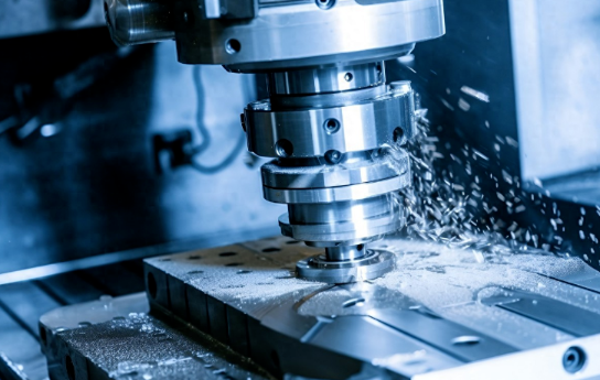
CNC machining operates as a subtractive process—a cutting machine removes material from solid blocks to create finished shapes. This fundamental approach delivers mechanical advantages that alternatives struggle to match in specific scenarios.
Consider precision first. According to comparative analysis from manufacturing experts, CNC machining typically achieves tolerances of ±0.01mm or better, making it well-suited for functional parts demanding high dimensional accuracy. Compare this to 3D printing technologies: FDM offers approximately ±0.2mm accuracy, while even higher-end SLA and MJF processes deliver ±0.05mm to ±0.1mm. When your machined components require tight-fitting assemblies, CNC mechanical systems provide the precision you need.
Material compatibility represents another CNC strength. Production machining handles virtually any material—metals, plastics, composites, even wood. EDM limits you to electrically conductive materials only. 3D printing continues expanding its material options, but printed material properties often differ from traditionally manufactured counterparts. When your application demands specific mechanical properties from proven materials, CNC delivers.
Surface finish directly from the machine favors CNC and EDM over additive methods. A properly machined surface often requires minimal post-processing, while 3D-printed parts typically show layer lines requiring sanding, polishing, or chemical smoothing. EDM produces excellent finishes on conductive materials—often requiring no additional finishing.
Choosing the Right Manufacturing Method
The best manufacturing method depends on your specific requirements. Here's how the alternatives compare mechanically:
3D Printing (Additive Manufacturing) builds parts layer by layer from digital models. It excels at complex internal geometries, lattice structures, and organic shapes that would be impossible or uneconomical with subtractive methods. According to Replique's production analysis, additive manufacturing typically offers lower total cost for 1–100 units due to minimal setup and tooling requirements. However, dimensional accuracy and mechanical properties generally fall short of CNC-machined equivalents.
Manual Machining relies on skilled operators controlling mills and lathes by hand. While it offers flexibility for one-off parts and repairs, repeatability suffers compared to computer-controlled alternatives. Human operators cannot match the positioning accuracy and consistency of servo-driven CNC mechanical systems. Manual methods make sense for simple repairs, low-volume custom work, or situations where CNC equipment isn't available.
Electrical Discharge Machining (EDM) erodes conductive materials using controlled electrical discharges. Wire EDM achieves tolerances as tight as ±0.005mm—surpassing even precision CNC work for intricate profiles. According to detailed comparisons, EDM handles extremely hard materials and produces burr-free, high-quality finishes. The trade-offs? Slower material removal rates, higher operational costs, and restriction to conductive materials only.
| Factor | CNC Machining | 3D Printing | Manual Machining | EDM |
|---|---|---|---|---|
| Mechanical Precision | ±0.01mm typical; excellent repeatability | ±0.05mm to ±0.2mm depending on technology | Operator-dependent; lower repeatability | ±0.005mm achievable; highest precision |
| Material Options | Broadest range: metals, plastics, composites, wood | Growing selection; properties may differ from bulk materials | Same as CNC but limited by operator skill | Conductive materials only (metals, some ceramics) |
| Production Speed | Days to weeks depending on complexity | Hours to days; fastest for initial prototypes | Highly variable; operator-paced | Days to weeks; slower material removal |
| Cost Efficiency | Best at 100–300+ parts; setup costs amortized | Most economical for 1–100 units | Lowest equipment cost; high labor cost | Higher operational costs; justified for unique capabilities |
| Surface Finish | Good to excellent; post-processing available | Layer lines visible; typically requires finishing | Depends on operator skill | Excellent; often needs no post-processing |
| Design Complexity | External features excel; internal features challenging | Handles internal channels, lattices, organic shapes | Limited by tool access and operator capability | Intricate 2D profiles and complex cavities |
Machine fabrication through CNC becomes increasingly cost-effective as volumes rise. According to production economics research, CNC machining manufacturing typically becomes more economical than additive methods once you reach 100–300 parts, depending on geometry and finishing requirements. Setup costs that seem high for single prototypes distribute across larger runs, dramatically reducing per-part expense.
When does each method make sense? Choose 3D printing for rapid concept validation, complex internal structures, or highly customized low-volume production. Select EDM when working with hardened materials requiring intricate details or when tolerances exceed CNC capabilities. Reserve manual machining for repairs, modifications, or situations where CNC access is impractical.
But for functional prototypes requiring material fidelity, production parts demanding consistent quality, or any application where mechanical properties must match final-use conditions—machining manufacturing through CNC mechanical systems remains the benchmark. The combination of precision, material versatility, and production scalability explains why CNC continues dominating industries from aerospace to medical devices.
Understanding these trade-offs positions you to make informed decisions about which process best serves each project's requirements. With manufacturing method selection clarified, the next consideration becomes equally practical: how do you evaluate and select quality CNC machining services when your projects require external capabilities?
Selecting Quality CNC Mechanical Services and Equipment
You've compared CNC machining against alternatives and understand where mechanical precision truly matters. But here's the practical challenge: when your projects require external manufacturing capabilities, how do you identify providers whose cnc equipment actually delivers the precision you need? Selecting quality CNC services involves more than comparing price quotes—it requires evaluating mechanical capabilities, tolerance standards, and quality systems that directly impact your finished cnc parts.
Whether you're sourcing cnc machined parts for prototypes or production runs, the evaluation criteria remain consistent. Let's examine what separates capable providers from those who merely claim precision.
Tolerance Standards That Define Quality
Tolerance capability serves as the most direct indicator of cnc machining equipment quality. According to Modus Advanced's precision manufacturing analysis, standard CNC machining typically achieves tolerances of ±0.127mm (±0.005"), while tight-tolerance services reach ±0.0254mm (±0.001") or better. For the most demanding applications, industry leaders deliver tolerances as tight as ±0.0025mm (±0.0001")—requiring specialized equipment, environmental controls, and comprehensive quality systems.
Understanding tolerance classifications helps you specify requirements appropriately without over-engineering:
- Standard tolerances (±0.005" to ±0.010"): Suitable for general manufacturing, non-critical dimensions, and applications where fit requirements are generous
- Precision tolerances (±0.001" to ±0.002"): Required for functional assemblies, moving components, and applications where dimensional relationships affect performance
- Tight tolerances (±0.0001" to ±0.0005"): Reserved for critical applications in medical devices, aerospace systems, and precision instruments where dimensional accuracy impacts safety or function
Each tolerance level demands corresponding equipment investment. Achieving tight tolerances requires thermal compensation systems maintaining temperatures within ±1°C, high-resolution encoders monitoring position to sub-micron accuracy, and spindle runout specifications below 0.0013mm. When evaluating what is cnc equipment capability at a potential supplier, ask about these specifications—they reveal whether the mechanical systems can actually deliver claimed precision.
Tighter tolerances increase manufacturing costs significantly. According to LS Manufacturing's procurement guide, professional CNC machining quotes may be 10-20% higher initially, but through quality stability, delivery guarantees, and value-added technical services, they can reduce total costs by more than 30%. Specifying tolerances tighter than your application actually requires wastes resources without improving function.
Certifications That Ensure Mechanical Excellence
Quality certifications provide documented evidence that a provider's cnc machining tools and processes meet established standards. According to Modo Rapid's certification analysis, certifications act as a safety net, confirming that supplier processes are audited and reliable. But which certifications matter for mechanical precision?
ISO 9001 establishes the baseline. This certification verifies the supplier maintains documented quality control processes, continuous improvement practices, and systematic approaches to meeting customer requirements. Think of it as a driver's license for manufacturing—necessary but not sufficient for demanding applications.
IATF 16949 layers automotive-specific requirements onto ISO 9001. This certification requires defect prevention systems, statistical process control, and lean production practices. For automotive cnc machined parts, this certification is non-negotiable. Providers like Shaoyi Metal Technology demonstrate their commitment to automotive quality standards through IATF 16949 certification, combining it with Statistical Process Control (SPC) to ensure high-tolerance components meet stringent requirements consistently.
AS9100 addresses aerospace and defense requirements, adding safety protocols, risk management, and traceability beyond standard quality systems. If your parts fly, this certification matters.
ISO 13485 applies specifically to medical device manufacturing, ensuring compliance with biocompatibility requirements and production environmental controls essential for patient safety.
Beyond certifications, evaluate these practical capability indicators:
- Measurement systems: Coordinate measuring machines (CMMs) with measurement uncertainties of ±0.0005mm or better indicate serious precision capability
- Statistical Process Control: Active SPC programs demonstrate ongoing monitoring rather than just final inspection—catching drift before it produces non-conforming parts
- Material traceability: Complete documentation from raw material certification through finished part inspection protects against material substitution and supports failure analysis if needed
- Environmental controls: Temperature-controlled machining environments (typically 20°C ±1°C) indicate attention to thermal stability that affects dimensional accuracy
- Equipment calibration programs: Regular calibration schedules for both production equipment and measurement instruments ensure accuracy doesn't degrade undetected
Production volume capability deserves attention during evaluation. Some providers excel at prototyping but struggle with production quantities. Others require minimum orders that exceed your needs. The ideal partner scales seamlessly from rapid prototyping to mass production—handling single-piece validation runs with the same quality systems applied to thousand-piece orders. Shaoyi Metal Technology exemplifies this flexibility, delivering high-tolerance components with lead times as fast as one working day while supporting complex chassis assemblies at production volumes.
Consider communication and project management capabilities alongside technical factors. According to procurement experts, effective project management and transparent communication prove crucial for on-time, on-budget delivery. Digital platforms enabling real-time progress tracking, engineering change management systems, and dedicated project managers indicate organizational maturity that reduces supply chain risk.
Design for manufacturability (DFM) analysis reveals whether a provider approaches your project as a partner or merely a vendor. Suppliers who analyze your designs and suggest optimizations—reducing part count, recommending economical alternative materials, or identifying tolerance zones that can be relaxed without affecting function—deliver value beyond basic machining. This engineering collaboration often reduces total costs by 30% or more while improving part quality.
With these evaluation criteria in mind, you're equipped to select cnc machining equipment providers whose mechanical capabilities match your actual requirements. The final step connects all these mechanical fundamentals into practical expertise you can apply immediately—transforming knowledge into manufacturing success.
Mastering CNC Mechanical Fundamentals for Manufacturing Success
You've journeyed through the complete mechanical landscape of CNC systems—from spindles and ball screws to G-code translation, material interactions, and quality certification standards. But here's what truly matters: how do you apply this knowledge in practice? Whether you're answering what does cnc stand for to a new colleague or diagnosing why parts drift out of tolerance during a production run, mechanical understanding transforms you from someone who operates machines into someone who masters them.
Understanding what does cnc mean goes far beyond memorizing that it stands for "computer numerical control." It means recognizing that every programmed movement depends on mechanical components working in precise harmony. It means knowing why thermal expansion affects ball screw accuracy. It means diagnosing chatter before it ruins expensive workpieces. This depth of knowledge separates exceptional practitioners from those who simply follow procedures.
Applying Mechanical Knowledge in Practice
Think about what is a cnc operator who truly excels at their craft. They don't just load programs and press cycle start. They listen for changes in spindle sound that signal bearing wear. They check coolant concentration because they understand how heat affects dimensional stability. They adjust feed rates based on material response, not just programmed values. This mechanical awareness translates directly into better parts, longer machine life, and fewer production disruptions.
The meaning of cnc machinist extends beyond machine operation into diagnostic capability. When surface finish degrades, a mechanically-informed technician considers spindle runout, tool holder balance, and linear guide preload—not just cutting parameters. When positioning errors appear, they investigate backlash, thermal compensation settings, and servo tuning. This systematic approach, rooted in mechanical understanding, solves problems faster and prevents recurrence.
According to industry analysis, skilled technicians play a pivotal role in CNC maintenance success—their expertise in identifying, diagnosing, and addressing issues is instrumental in maintaining optimal performance. Technology evolves continuously, making ongoing learning essential for keeping pace with machining advancements. What is a cnc machinist in today's manufacturing environment? Someone who combines hands-on mechanical skills with continuous technical education.
The operators who understand mechanical fundamentals consistently outperform those who treat CNC machines as black boxes. They catch problems earlier, optimize processes more effectively, and deliver higher quality parts—because they understand not just what the machine does, but how and why it does it.
Building Your CNC Mechanical Expertise
Developing mechanical mastery requires deliberate practice across several areas. Start by connecting every programming decision to its mechanical consequence. When you specify a feed rate, visualize the forces transmitted through ball screws and linear guides. When you program rapid moves, consider the acceleration stress on servo motors. This mental model transforms abstract code into physical understanding.
Machining for manufacturing success demands attention to the entire mechanical system. Build habits around preventive maintenance—the daily wiping, weekly filter checks, and monthly alignment verification that keep mechanical components performing optimally. As maintenance experts emphasize, viewing regular maintenance as a long-term investment rather than an expense enhances machine lifespan and ensures reliable operation for years.
Document your observations and lessons learned. Note which materials challenge your specific machine's mechanical systems. Record the symptoms that preceded component failures. Track how parameter changes affect part quality. Over time, this personal knowledge base becomes invaluable for troubleshooting and process optimization.
Seek out opportunities to observe maintenance procedures firsthand. Watch spindle rebuilds, ball screw replacements, and alignment calibrations when technicians perform them. Understanding how components are serviced deepens your appreciation for keeping them healthy through proper operation and maintenance.
Certified manufacturers demonstrate how mechanical expertise translates into real-world performance. Shaoyi Metal Technology exemplifies this connection—their IATF 16949 certification and Statistical Process Control systems reflect deep mechanical understanding applied systematically. Delivering high-tolerance components with lead times as fast as one working day while handling complex chassis assemblies requires mechanical systems maintained to exacting standards. Their capability to scale from rapid prototyping to mass production demonstrates how mechanical excellence supports manufacturing flexibility.
Whether you're an operator developing diagnostic skills, a maintenance technician expanding troubleshooting capability, or an engineer specifying equipment for new production lines, mechanical fundamentals provide the foundation for informed decisions. The principles covered throughout this article—component functions, axis configurations, material interactions, programming implications, maintenance protocols, and quality standards—form a comprehensive framework for CNC mechanical mastery.
Apply this knowledge incrementally. Start with the mechanical systems most relevant to your current work. Build understanding through observation, practice, and continuous learning. The path from CNC user to CNC expert runs directly through mechanical comprehension—and that journey begins with every part you make, every problem you solve, and every system you maintain.
Frequently Asked Questions About CNC Mechanical Systems
1. What is CNC in mechanical engineering?
CNC stands for Computer Numerical Control, referring to computerized operation of machining tools. In mechanical engineering, CNC systems combine digital control with precision mechanical components—spindles, ball screws, linear guides, and servo motors—to execute programmed movements with micron-level accuracy. These mechanical systems translate electrical signals into controlled physical motion while withstanding significant cutting forces and thermal variations during manufacturing operations.
2. What is a mechanical technician CNC?
A CNC mechanical technician is a skilled professional who operates, programs, and maintains computer numerically controlled machines. Beyond basic operation, they diagnose mechanical issues like spindle problems, axis alignment, and backlash. They understand how components interact, perform preventive maintenance on ball screws and linear guides, and troubleshoot servo motor issues. Certified providers like Shaoyi Metal Technology employ technicians with expertise in IATF 16949 quality standards and Statistical Process Control.
3. Do CNC machinists make a lot of money?
CNC machinists earn competitive wages, with average salaries around $27.43 per hour in the United States. Earnings vary based on experience, certifications, and specialization. Machinists who understand mechanical fundamentals—diagnosing bearing wear, optimizing feed rates, and performing preventive maintenance—command higher wages. Those certified in precision machining or working with high-tolerance components in aerospace or automotive sectors typically earn above-average compensation.
4. What are the essential mechanical components in a CNC machine?
Every CNC machine relies on five core mechanical systems: spindles (rotating the cutting tool or workpiece), ball screws (converting rotary motion to linear travel with over 90% efficiency), linear guides (ensuring straight, friction-free motion), servo motors (providing precisely controlled rotational force with positioning accuracy of 2-5 micrometers), and bearings (supporting high-speed rotation and load capacity). These components work together to achieve tolerances of approximately ±0.005 inches.
5. How do I choose between 3-axis and 5-axis CNC machines?
Choose based on part geometry, not capability assumptions. 3-axis machines offer highest inherent rigidity for flat surfaces and prismatic parts. 5-axis machines enable complex sculptured surfaces but introduce additional mechanical complexity and potential deflection points. For parts requiring machining at fixed angles, 3+2 positioning offers a middle ground—rotary axes lock during cutting for maximum rigidity. Match mechanical capability to geometric requirements rather than assuming more axes means better results.