 Small batches, high standards. Our rapid prototyping service makes validation faster and easier —

Machined Parts Decoded: From Material Choice To Final Inspection
What Are Machined Parts and Why They Matter
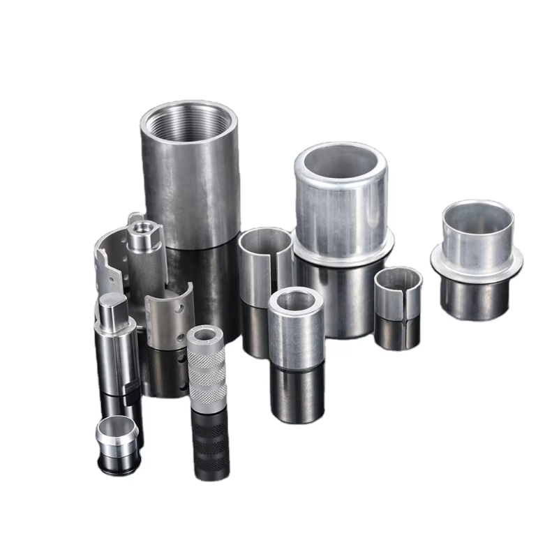
Ever wondered how the precision components inside your car engine or aircraft turbine are created? The answer lies in one of manufacturing's most fundamental processes. Machined parts are components produced by systematically removing material from a solid workpiece using cutting tools—a technique that has shaped modern industry for over a century.
Machined parts are precision components manufactured through subtractive processes, where cutting tools remove material from solid metal or plastic workpieces to achieve exact specifications, tight tolerances, and complex geometries.
Unlike 3D printing that builds objects layer by layer, or casting that pours molten material into molds, machining works in reverse. You start with more material than you need, then carefully cut away everything that isn't your final part. This subtractive approach delivers unmatched dimensional accuracy and surface quality that other methods struggle to replicate.
Subtractive Manufacturing Explained
So, what's machining in practical terms? Picture a sculptor chipping away at a marble block to reveal a statue hidden inside. Subtractive manufacturing follows the same principle—except the "sculptor" is a computer-controlled cutting tool, and the "marble" might be aluminum, steel, titanium, or engineering plastic.
The process typically begins with a solid block, bar, or sheet of raw material called a workpiece. Precision cutting tools then remove material through various operations—milling, turning, drilling, or grinding—until the final geometry emerges. Each pass of the tool brings the workpiece closer to its intended shape, with tolerances often measured in thousandths of an inch.
This stands in stark contrast to additive manufacturing (3D printing), which builds parts by depositing material layer upon layer. While additive processes excel at creating complex internal structures with minimal waste, they often require post-process machining to achieve the dimensional accuracy and surface finish that machined components deliver straight off the machine.
Why Machining Remains Industry Standard
With all the buzz around 3D printing and advanced manufacturing technologies, you might wonder why traditional machining still dominates. The answer comes down to three critical factors:
- Unrivaled precision: CNC machining achieves tolerances as tight as ±0.001mm—significantly better than casting or 3D printing can deliver without secondary operations.
- Material versatility: Virtually any metal, alloy, or engineering plastic can be machined, from soft aluminum to hardened tool steel, titanium, and high-performance polymers like PEEK.
- Scalability: The same equipment that produces a single prototype can manufacture thousands of production parts with identical specifications.
The numbers tell the story of just how essential machined components remain. According to Cognitive Market Research, the global machining market reached USD 355.8 billion in 2024 and is projected to grow at a 5.2% CAGR through 2031. North America alone accounts for over 40% of this market, driven by automotive, aerospace, and defense sectors that demand precision-engineered machine components.
The machining industry continues to evolve, but its core value proposition remains unchanged. When your application requires tight tolerances, superior surface finishes, and proven mechanical properties, machined parts deliver results that alternative manufacturing methods simply cannot match. Whether you're prototyping a single concept or scaling to production volumes, understanding how these components are created forms the foundation for successful project outcomes.
Core Machining Processes and When to Use Each
Choosing the right machining process can feel overwhelming when you're staring at a CAD model and wondering how to bring it to life. Should you mill it? Turn it? Maybe both? The truth is, each cnc machining parts process excels in specific scenarios—and understanding these distinctions can save you significant time and money while delivering superior results.
Let's break down the major machining processes and clarify exactly when each one shines.
CNC Milling vs Turning Operations
Here's the fundamental distinction that drives most process decisions: in CNC turning, your workpiece rotates while the cutting tool stays stationary. In CNC milling, the opposite occurs—the workpiece remains fixed while a rotating cutter moves across multiple axes to remove material.
Think of CNC turning like a potter's wheel. The raw material (typically a round bar) spins at high speed while a cutting tool shapes it. This makes turning the go-to choice for cylindrical parts—shafts, pins, bushings, and any component with rotational symmetry. The continuous chip flow produces exceptionally smooth surface finishes on round diameters.
CNC milling, on the other hand, resembles sculpting with a rotating cutting tool. The workpiece stays put while the spindle moves along the X, Y, and Z axes to carve away material. This process dominates when you need flat surfaces, pockets, slots, or complex 3D contours. Milled parts range from simple brackets to intricate aerospace housings with compound curves.
Here's how axis configurations affect your cnc milled parts capabilities:
- 3-axis milling: Linear movement along X, Y, and Z axes. Ideal for flat parts, simple pockets, and basic drilling operations. Most cost-effective for straightforward geometries.
- 4-axis milling: Adds rotary movement (A-axis) around the X-axis. Enables machining multiple faces without repositioning, perfect for parts requiring features on different sides.
- 5-axis milling: Simultaneous movement along three linear and two rotary axes. Essential for complex sculptured surfaces, undercuts, and parts requiring tool access from virtually any angle.
The most intricate cnc machine part often requires both processes working together. Modern mill-turn centers combine turning and milling capabilities in a single setup—what manufacturers call "one and done" machining. This eliminates repositioning errors and dramatically reduces lead times for complex cnc mechanical parts.
Specialized Processes for Complex Geometries
Beyond standard milling and turning, several specialized processes address specific manufacturing challenges:
Swiss-type machining represents the pinnacle of precision for small, intricate components. These specialized lathes include a guide bushing that supports the workpiece extremely close to the cutting zone, minimizing deflection and enabling remarkably tight tolerances on long, slender parts. Medical device manufacturers rely on Swiss machining for surgical instruments and implantable components where micron-level accuracy is non-negotiable.
Grinding steps in when surface finish requirements exceed what conventional cutting can achieve. Using abrasive wheels rather than cutting edges, grinding produces mirror-like finishes and holds tolerances measured in millionths of an inch. The trade-off? It's significantly slower and more expensive than other methods—so reserve grinding for surfaces where ultra-fine finishes actually matter functionally.
Drilling might seem straightforward, but precision hole-making involves considerations beyond simply poking through material. Depth-to-diameter ratios, positional accuracy, and hole quality all factor into selecting between standard drilling, gun drilling for deep holes, or boring operations for critical diameters.
The following table provides a comprehensive comparison to guide your cnc precision machining parts process selection:
| Process | Typical Tolerances | Ideal Geometries | Material Compatibility | Relative Cost | Production Speed |
|---|---|---|---|---|---|
| CNC Turning | ±0.001" to ±0.005" | Cylindrical, conical, round profiles | All metals, most plastics | Low to Medium | Fast for round parts |
| 3-Axis Milling | ±0.002" to ±0.005" | Flat surfaces, pockets, slots, simple 3D | All metals, plastics | Low to Medium | Fast for simple parts |
| 4-Axis Milling | ±0.001" to ±0.003" | Multi-face features, indexed holes | All metals, plastics | Medium | Moderate |
| 5-Axis Milling | ±0.0005" to ±0.002" | Complex contours, undercuts, aerospace parts | All metals, composites, plastics | High | Slower but fewer setups |
| Swiss-Type Turning | ±0.0002" to ±0.001" | Small, slender, high-precision components | Metals, engineering plastics | High | Excellent for small parts |
| Grinding | ±0.0001" to ±0.0005" | Precision diameters, ultra-fine surfaces | Hardened metals, ceramics | Very High | Slow |
| Drilling/Boring | ±0.001" to ±0.005" | Holes, bores, counterbores | All machinable materials | Low | Fast |
When selecting a process for your precision machining part, start with the fundamental question: is my component primarily round or does it feature complex, non-symmetrical geometry? Round parts almost always begin on a lathe. Everything else starts with milling. From there, consider tolerance requirements, surface finish specifications, and production volumes to refine your selection.
The most challenging parts often combine processes strategically. A shaft with milled flats, drilled cross-holes, and ground bearing surfaces might visit three different machines—or be completed in one setup on an advanced mill-turn center. Understanding each process's strengths helps you design parts that are not only functional but economically manufacturable.
Of course, choosing the right process is only half the equation. The material you select dramatically impacts machinability, cost, and final part performance—which brings us to the critical topic of material selection.
Material Selection for Machined Components
You've nailed down the right machining process—but here's the thing: even the most advanced 5-axis mill won't deliver optimal results if you've chosen the wrong material. Material selection directly impacts everything from machining time and tool wear to final part performance and cost. Yet many engineers default to familiar materials without fully considering whether alternatives might deliver better outcomes.
Let's decode the most common materials for precision machined components and establish clear selection criteria you can reference for your next project.
Metal Alloys for Precision Components
When specifying machined metal parts, you're typically choosing between aluminum alloys, stainless steels, carbon steels, brass, or titanium. Each family offers distinct advantages—and understanding these trade-offs prevents costly mistakes.
Aluminum Alloys: The Versatility Champions
Aluminum dominates precision machined metal parts production for good reason. Its excellent machinability means faster cycle times, reduced tool wear, and lower per-part costs. But not all aluminum alloys are created equal.
6061 aluminum is the workhorse grade, offering outstanding versatility with good strength, excellent corrosion resistance, and superior weldability. According to Thyssenkrupp Materials, 6061 has a density of 2.7 g/cm³—nearly identical to pure aluminum—making it ideal for weight-sensitive applications. You'll find it everywhere: automotive components, marine fittings, furniture, electronics housings, and structural assemblies.
7075 aluminum takes a different approach. Often called "aircraft grade," this alloy delivers one of the highest strength-to-weight ratios available in aluminum. Its density of 2.81 g/cm³ is slightly higher than 6061, but the tensile strength jumps dramatically. The trade-off? Reduced formability and weldability. Reserve 7075 for aerospace, defense, and high-stress applications where strength trumps fabrication flexibility.
- Choose 6061 when: You need excellent corrosion resistance, weldability, or a balance of properties across diverse applications.
- Choose 7075 when: Maximum strength matters more than formability, particularly in aerospace or military components.
Stainless Steels: Corrosion Resistance Meets Strength
Stainless steel accounts for a massive segment of metal machining parts, but selecting the right grade requires understanding subtle differences that impact both machinability and performance.
As Atlantic Stainless explains, all three common grades (303, 304, 316) are austenitic—non-magnetic steels containing high chromium and nickel with low carbon content.
Type 303 is specifically engineered for machinability. Added sulfur makes it the most readily machinable austenitic stainless, ideal for nuts, bolts, gears, screws, shafts, and bushings. The trade-off? Slightly reduced corrosion resistance compared to 304.
Type 304 represents the global standard, accounting for over 50% of worldwide stainless steel consumption. Its exceptional corrosion resistance, outstanding weldability, and excellent formability make it the default choice for kitchen equipment, food processing, architectural applications, and general industrial use.
Type 316 adds 2-3% molybdenum for superior pitting and crevice corrosion resistance. This makes it essential for marine environments, chemical processing, pharmaceutical manufacturing, and any application involving high chloride exposure.
- Choose 303 when: Machinability is paramount and parts won't face extreme corrosive environments.
- Choose 304 when: You need the best all-around balance of corrosion resistance, weldability, and cost.
- Choose 316 when: Marine, chemical, or high-chloride environments demand maximum corrosion protection.
Brass and Titanium: Specialized Solutions
Custom brass parts excel in applications requiring excellent electrical conductivity, natural lubricity, or antimicrobial properties. Brass machines beautifully—producing clean chips and achieving excellent surface finishes with minimal effort. Plumbing fittings, electrical connectors, and decorative hardware frequently rely on brass for these characteristics.
Titanium occupies the opposite end of the machinability spectrum. Its exceptional strength-to-weight ratio and biocompatibility make it essential for aerospace and medical implant applications. However, titanium's low thermal conductivity causes heat buildup at the cutting edge, accelerating tool wear and demanding specialized machining parameters. Expect significantly higher costs when specifying titanium components.
Engineering Plastics in Machined Applications
Not every precision mechanical part requires metal. Engineering plastics like PEEK and Delrin offer compelling advantages for specific applications—lighter weight, chemical resistance, electrical insulation, and often lower machining costs.
PEEK (Polyether Ether Ketone) sits at the top of the engineering plastics hierarchy. Its remarkable combination of high-temperature stability (continuous use to 480°F), chemical resistance, and mechanical strength makes it suitable for demanding aerospace and medical applications. PEEK machines well but requires proper tooling and parameters to prevent surface melting.
Delrin (Acetal/POM) delivers excellent dimensional stability, low friction, and outstanding fatigue resistance at a fraction of PEEK's cost. It's the go-to choice for gears, bearings, bushings, and precision mechanical parts where metal isn't necessary.
| Material | Machinability Index | Tensile Strength Range | Relative Cost | Best-Fit Applications |
|---|---|---|---|---|
| Aluminum 6061 | Excellent (90%) | 40-45 ksi | Low | General purpose, marine, automotive, electronics |
| Aluminum 7075 | Good (70%) | 73-83 ksi | Medium | Aerospace, defense, high-stress structural |
| Stainless 303 | Good (60%) | 85-95 ksi | Medium | Fasteners, shafts, gears, heavily machined parts |
| Stainless 304 | Moderate (45%) | 75-90 ksi | Medium | Food processing, architectural, general industrial |
| Stainless 316 | Moderate (40%) | 75-85 ksi | Medium-High | Marine, chemical, pharmaceutical, medical |
| Brass (360) | Excellent (100%) | 55-60 ksi | Medium | Electrical, plumbing, decorative, custom brass parts |
| Titanium Grade 5 | Poor (25%) | 130-145 ksi | Very High | Aerospace, medical implants, high-performance |
| PEEK | Good (65%) | 14-16 ksi | Very High | Aerospace, medical, high-temp applications |
| Delrin | Excellent (85%) | 9-11 ksi | Low | Gears, bearings, bushings, low-friction components |
When comparing metal machined options, remember that machinability directly impacts cost. A part that takes twice as long to machine costs significantly more—regardless of raw material price. Balance material performance requirements against manufacturing economics, and don't over-specify when a more machinable alternative meets your functional needs.
With your material selected, the next challenge becomes designing features that are actually manufacturable without driving costs through the roof. That's where design-for-manufacturability guidelines become essential.
Design Guidelines That Reduce Cost and Lead Time
You've selected your material and identified the right machining process. Now comes the moment that separates costly redesigns from smooth production runs: translating your design intent into features that machines can actually cut efficiently. Design for manufacturability (DFM) isn't about limiting creativity—it's about understanding how your design decisions directly impact what happens on the shop floor.
Here's the reality: according to Five Flute, programming and job setup represent significant fixed costs that get amortized across your total part quantity. Every feature that complicates these steps multiplies your per-part cost, especially at prototype volumes. But when you design with manufacturability in mind? You'll see faster quotes, shorter lead times, and precision machined parts that arrive right the first time.
Let's walk through the specific rules that keep your custom machined parts manufacturable and cost-effective.
Critical Dimensions and Feature Rules
Wall Thickness Minimums
Thin walls create headaches in machining. As wall thickness decreases, the material loses stiffness—leading to vibration during cutting, reduced accuracy, and potential part damage. The physics are simple: a thin wall deflects under cutting forces, making it impossible to hold tight tolerances.
- Metals: Maintain minimum wall thickness of 0.8mm (0.032"). Below 0.5mm becomes extremely challenging regardless of material.
- Plastics: Aim for at least 1.5mm (0.060") minimum. Plastics are prone to warping from residual stresses and softening from heat buildup during machining.
- Unsupported walls: Consider the wall's height-to-thickness ratio. A tall, thin wall acts like a diving board—it will vibrate and may even crack under cutting pressure.
Hole Depth-to-Diameter Ratios
Standard drill bits have limited reach before chip evacuation and tool deflection become problematic. Push too deep without proper tooling, and you'll get wandering holes, poor surface finish, or broken tools.
- Recommended depth: 4× the nominal hole diameter for standard drilling operations.
- Typical maximum: 10× diameter with careful technique and peck drilling cycles.
- Feasible with specialty tooling: Up to 40× diameter using gun drills or deep-hole drilling equipment (minimum 3mm diameter).
- Blind hole floors: Standard drills leave a 135° conical bottom. If you need a flat floor, the hole must be machined with an end mill—adding time and cost.
Internal Corner Radii Requirements
This is where many engineers trip up. Since cutting tools are round, every internal corner in a milled part inherits a radius equal to the tool's radius. Designing sharp internal corners is impossible to machine.
- Minimum internal corner radius: At least ⅓ of the cavity depth. This ensures a suitably sized tool can reach the full depth without excessive deflection.
- For better surface finish: Increase corner radii slightly (by 1mm or more) above the minimum. This allows the tool to follow a smooth circular path rather than stopping at a sharp 90° corner.
- Need truly sharp corners? Consider a T-bone undercut—a machining workaround that creates clearance for mating parts without demanding the impossible.
Pocket and Cavity Depth Guidelines
Deep pockets require long tools, and long tools deflect more under cutting forces. As Hubs notes, tool deflection, chip evacuation, and vibrations become increasingly problematic as depth-to-width ratios grow.
- Recommended cavity depth: Maximum 4× the cavity width for standard tooling.
- Extended reach: Depths up to 6× tool diameter are achievable but may require specialty tooling that adds cost.
- Deep cavity machining: Ratios up to 30:1 are possible with specialized extended-reach or relieved-shank end mills—but expect significant cost and lead time impacts.
- Variable depth strategy: If you need deeper features, consider designing stepped or variable-depth cavities that allow larger tools to remove the bulk of material.
Thread Specifications
Threads are commonly added to machining parts, but proper specification prevents unnecessary complications:
- Minimum thread size: M6 or larger is preferred because CNC threading tools can cut them efficiently. Smaller threads (down to M2) require taps, which increase tap breakage risk.
- Thread engagement length: 1.5× the nominal diameter captures the majority of thread strength. Going beyond 3× diameter provides virtually no additional holding power—it just adds machining time.
- Blind hole threads: For tapped threads (smaller than M6), add an unthreaded depth of at least 1.5× diameter at the hole bottom to allow chip clearance and tap runout.
Avoiding Costly Design Mistakes
Undercut Limitations
Undercuts—features that can't be accessed directly from above—require special tooling and often additional setups. While they're sometimes unavoidable, understanding their constraints helps you design smarter.
- T-slot undercuts: Standard tooling covers widths between 3mm and 40mm. Stick to whole-millimeter increments or standard inch fractions to use off-the-shelf cutters.
- Dovetail undercuts: 45° and 60° angles are standard. Other angles (5° to 120° in 10° increments) exist but are less commonly stocked.
- Clearance rule: When designing internal undercuts, leave clearance equal to at least 4× the undercut depth between the machined wall and adjacent features.
Text and Engraving Specifications
Adding part numbers, logos, or other markings seems simple—until the machine shop explains why your 8-point font requires specialty micro-tooling.
- Minimum font size: 20-point sans-serif fonts (Arial, Verdana) work reliably. Many CNC machines have these fonts pre-programmed.
- Engraved vs. embossed: Always prefer engraved (recessed) text. Embossed text requires removing material around each character—dramatically increasing machining time.
- Depth: 5mm maximum depth for engraved features keeps tool lengths manageable.
Special Considerations for Large and Complex Parts
When machining large parts, additional factors come into play. Thermal expansion becomes significant—a 1-meter aluminum part can grow by 0.2mm with just a 10°C temperature change. Large parts also require more substantial workholding and may need stress-relief operations between roughing and finishing passes to maintain dimensional stability.
For complex machined parts requiring features on multiple faces, minimize the number of setups. Each time a part is repositioned, you introduce potential alignment errors and add manual labor time. Design features that can be accessed from opposing directions (top and bottom) to enable efficient two-operation machining with standard vise fixtures.
Design for Assembly Considerations
Think beyond the individual component. When your part joins others in an assembly of machined parts, ensure mating features share appropriate tolerances. Features with tight relative position requirements should be machined in the same setup whenever possible—this leverages the CNC machine's inherent positional accuracy (approximately ±10 microns) rather than relying on fixture repeatability between operations.
The bottom line? Proper DFM doesn't constrain innovation—it channels it toward solutions that work on the shop floor. Engineers who master these guidelines find their designs quoted faster, manufactured more accurately, and delivered in shorter timeframes. Every revision cycle you eliminate by getting the design right initially accelerates your entire project timeline.
Of course, even perfectly designed features need proper tolerance and surface finish specifications to communicate your requirements clearly. That's exactly what we'll decode next.
Tolerances and Surface Finishes Explained
You've designed your part with manufacturable features and selected the ideal material. Now comes a decision that can quietly inflate your costs by 50% or more—or save you significant money if you get it right. Tolerance and surface finish specifications communicate your precision requirements to the machine shop, but specifying tighter values than your application actually needs? That's where budgets silently disappear.
Here's the reality that many engineers overlook: the relationship between tolerance and cost isn't linear—it's exponential. According to research on precision manufacturing economics, moving from ±0.05mm to ±0.02mm may raise costs by around 50%. But pushing further from ±0.02mm to ±0.01mm can multiply costs several times over. Why? You cross process-capability thresholds that demand slower feeds, tighter fixturing, temperature-controlled environments, and dramatically more inspection time.
Let's decode what different tolerance and finish specifications actually mean for your precision machined products—and when each level makes functional sense.
Understanding Tolerance Classes
Tolerance defines the permissible limits of variation in a physical dimension. When you specify ±0.005" (±0.127mm), you're telling the machinist that the actual dimension can fall anywhere within that range and still be acceptable. The tighter you make that window, the more precision parts processing demands specialized equipment, slower cutting speeds, and rigorous inspection.
Standard Machining Tolerances (±0.005" / ±0.127mm)
This represents the typical capability of well-maintained CNC equipment running at efficient production speeds. Most precision machine parts fall into this category because it balances accuracy with cost-effectiveness. At these tolerances, you get:
- Fast cycle times—machines run at optimal feed rates
- Standard tooling and fixturing requirements
- Efficient inspection using standard measuring equipment
- Lower scrap rates and minimal rework
For many applications—structural brackets, enclosures, general mechanical assemblies—standard tolerances work perfectly. The parts fit, function, and perform without paying a premium for precision that adds no value.
Precision Tolerances (±0.001" / ±0.025mm or tighter)
When your application genuinely demands it—bearing fits, mating surfaces in precision assemblies, or components where microns matter functionally—precision tolerances become necessary. But understand what you're asking for:
- Slower cutting speeds to minimize thermal expansion and tool deflection
- Temperature-controlled machining environments in some cases
- CMM (Coordinate Measuring Machine) inspection rather than simple go/no-go gauges
- Higher scrap rates as parts near the edge of process capability
- Potentially multiple finishing passes after roughing operations
International standards like ISO 2768 and ISO 286 provide frameworks for specifying tolerances consistently. ISO 2768 defines general tolerances in Fine (f) and Medium (m) classes that apply by default when specific tolerances aren't called out. For features requiring tighter control, ISO 286 grades (IT6, IT7, IT8) specify exact limits based on nominal dimensions.
The most expensive tolerance is often the one that doesn't add functional benefit. Specify tight tolerances only where they directly impact part performance—every extra micron of precision costs more than you might expect.
When Does Each Tolerance Level Make Sense?
The following table links tolerance grades to practical applications, helping you specify appropriately for each precision-machined component in your design:
| Tolerance Grade | Typical Range | Applications | Cost Multiplier | Required Process |
|---|---|---|---|---|
| Commercial | ±0.010" (±0.25mm) | Non-critical features, rough structural parts | 1.0× (baseline) | Standard CNC milling/turning |
| Standard (ISO 2768-m) | ±0.005" (±0.127mm) | General mechanical parts, enclosures, brackets | 1.0-1.2× | Standard CNC with quality tooling |
| Fine (ISO 2768-f) | ±0.002" (±0.05mm) | Mating surfaces, locating features, assemblies | 1.3-1.5× | Precision CNC, careful fixturing |
| Precision (ISO 286 IT7) | ±0.001" (±0.025mm) | Bearing fits, shaft journals, critical interfaces | 1.8-2.5× | Precision grinding, temperature control |
| Ultra-Precision (ISO 286 IT6) | ±0.0005" (±0.013mm) | Aerospace interfaces, optical components, gauges | 3.0-5.0× | Grinding, lapping, controlled environment |
A smart tolerance strategy examines each feature individually. A European automotive supplier discovered that multiple non-critical features were specified at ±0.01mm when the assembly would function perfectly at ±0.03mm. By relaxing non-critical tolerances while maintaining tight specs only where functionally necessary, they reduced machining costs by approximately 22%.
Surface Finish Specifications Decoded
Surface finish describes the texture left on a machined surface—the microscopic peaks and valleys created by the cutting process. It's measured in Ra (Roughness Average), expressed in microinches (µin) or micrometers (µm). Lower Ra numbers mean smoother surfaces.
But here's what many specifications miss: surface finish has direct functional implications beyond aesthetics.
Understanding Ra Values
- 125-250 Ra µin (3.2-6.3 µm): Standard machined finish. Tool marks visible. Acceptable for non-critical surfaces, internal cavities, and parts receiving subsequent coating.
- 63-125 Ra µin (1.6-3.2 µm): Fine machined finish. Light tool marks may be visible. Suitable for mating surfaces, precision milled parts, and general functional surfaces.
- 32 Ra µin (0.8 µm): Smooth finish. Tool marks barely visible. Required for sealing surfaces, bearing contact areas, and high-quality precision machined parts.
- 16 Ra µin (0.4 µm): Very smooth. Approaches ground finish quality. Necessary for hydraulic components, high-speed bearing surfaces, and critical sealing applications.
- 8 Ra µin (0.2 µm) or better: Mirror finish. Requires grinding, lapping, or polishing. Reserved for optical components, gauges, and specialized high-quality precision machined parts.
Functional Implications of Surface Finish
Why does surface finish matter beyond appearance? Consider these functional impacts:
- Sealing surfaces: Smoother finishes create better seals. O-ring grooves typically need 32-63 Ra µin to prevent leakage paths along surface irregularities.
- Fatigue life: Rough surfaces create stress concentrations at microscopic peaks, potentially initiating cracks under cyclic loading. Critical rotating components often specify fine finishes for durability.
- Friction and wear: Counterintuitively, extremely smooth surfaces can increase friction in some applications because they lack the micro-valleys that retain lubricant. The optimal finish depends on the tribological system.
- Coating adhesion: Surfaces receiving paint, plating, or other coatings often benefit from controlled roughness that improves mechanical bonding.
The cost curve for surface finish mirrors that of tolerances. Achieving 32 Ra µin from standard machining requires additional finishing passes, sharper tooling, and slower speeds. Reaching 16 Ra µin or better typically requires grinding operations—a separate process with its own setup costs. Mirror finishes demand hand polishing or lapping, multiplying labor time dramatically.
For your machined products, match surface finish specifications to functional requirements. A structural bracket doesn't need a mirror finish—standard machined surfaces work perfectly. But that hydraulic valve body? Specify the sealing surfaces precisely while leaving non-functional areas at standard finish to control costs.
Understanding these specifications puts you in control of your precision machined part costs. Specify what you actually need—not what seems impressive on paper—and you'll receive accurate quotes, faster delivery, and parts that perform exactly as intended without paying for precision that adds no value.
With tolerances and finishes specified appropriately, the next consideration becomes understanding how different industries apply these principles—and what certifications matter for your specific application.
Industry Applications and Certification Requirements
Ever wonder why a seemingly identical CNC machined part costs dramatically more when destined for an aircraft versus a consumer appliance? The answer lies not in the machining itself but in the documentation, traceability, and quality systems wrapped around every step of production. Different industries don't just want precision cnc machined components—they demand proof that every part meets rigorous standards designed to protect lives, ensure reliability, and satisfy regulatory bodies.
Understanding why specific certifications matter in each sector helps you specify requirements appropriately and identify qualified suppliers. Let's explore the major industries where cnc machined components play critical roles—and the certification frameworks that govern them.
Automotive Precision Requirements
The automotive industry represents one of the largest consumers of machined parts globally, from engine components and transmission gears to chassis brackets and braking system parts. But here's what sets automotive apart: the relentless focus on consistency across massive production volumes.
Why IATF 16949 Certification Matters
IATF 16949 is the automotive industry's quality management standard, built upon ISO 9001 but adding sector-specific requirements that address the unique demands of manufacturing machine parts at scale. According to the International Automotive Task Force, major OEMs including BMW, Ford, General Motors, Mercedes-Benz, Stellantis, and Volkswagen publish customer-specific requirements that certified suppliers must follow.
What does this mean in practice? IATF 16949 certification signals that a mechanical parts assembly supplier has implemented:
- Advanced Product Quality Planning (APQP): Structured processes ensuring new parts meet specifications before production begins
- Production Part Approval Process (PPAP): Documented evidence that manufacturing processes consistently produce conforming parts
- Statistical Process Control (SPC): Real-time monitoring of critical dimensions to catch drift before defects occur
- Failure Mode and Effects Analysis (FMEA): Systematic identification and mitigation of potential failure points
- Full traceability: The ability to track any component back to specific raw material lots, machine settings, and operators
Typical Automotive Machined Components
- Transmission housings and internal gears
- Engine cylinder heads and blocks
- Steering knuckles and suspension components
- Brake calipers and master cylinder bodies
- Fuel injection system components
- Electric vehicle motor housings and battery tray brackets
For engineers designing automotive components, IATF 16949 compliance influences design decisions. Features must be inspectable, critical dimensions clearly identified, and tolerances achievable within statistical process capability. Procurement professionals should verify that potential suppliers hold current IATF 16949 certification—and understand which OEM-specific requirements apply to their projects.
Aerospace and Defense Standards
When a part failure can mean loss of life or mission failure, the stakes demand the most rigorous quality frameworks in manufacturing. Aerospace and defense represent the pinnacle of precision requirements for cnc machined parts.
AS9100: The Aerospace Quality Standard
AS9100 builds upon ISO 9001 but adds aerospace-specific requirements that go far beyond general quality management. As industry research indicates, over 80% of global aerospace companies require AS9100 certification from their CNC machining suppliers.
What makes AS9100 different? The standard emphasizes:
- Configuration management: Strict revision control ensuring the correct version of every drawing and specification is used
- First Article Inspection (FAI): Comprehensive AS9102-compliant documentation proving the first production part meets every specification
- Complete material traceability: Every component traceable from raw material heat numbers through final inspection
- Risk management: Formal processes for identifying and mitigating production risks
- Foreign Object Debris (FOD) prevention: Documented programs preventing contamination that could compromise flight safety
- Special process controls: Nadcap accreditation often required for heat treatment, surface finishing, and non-destructive testing
Defense-Specific Requirements
Defense applications add another layer: ITAR (International Traffic in Arms Regulations) compliance. ITAR-registered production facilities must control access to technical data, restrict foreign national involvement, and maintain security protocols that commercial operations don't require. Micro machined components for guidance systems, weapon platforms, and military vehicles often fall under these restrictions.
Typical Aerospace and Defense Components
- Structural airframe brackets and fittings
- Landing gear components
- Turbine engine housings and blades
- Flight control actuator bodies
- Satellite structural elements and thermal management components
- Missile guidance system housings
- Armored vehicle components
For aerospace applications, material certification becomes paramount. Parts often require specific aerospace-grade alloys (like 7075-T6 aluminum or Ti-6Al-4V titanium) with full mill certifications documenting chemical composition and mechanical properties. Every step from billet to finished part must be documented—and that documentation becomes a permanent part of the aircraft's maintenance records.
Medical Device and Life Sciences Applications
Medical devices occupy a unique position: they must meet precision requirements comparable to aerospace while also addressing biocompatibility—the ability of materials to perform safely within the human body. A surgical instrument or implantable component that fails can directly harm patients.
Regulatory Framework: ISO 13485 and FDA Requirements
While ISO 9001 provides the quality management foundation, medical device manufacturing requires ISO 13485 certification specifically designed for the sector. In the United States, FDA 21 CFR Part 820 establishes Quality System Regulations that align with ISO 13485 principles.
According to manufacturing experts, medical device parts suppliers must address:
- Biocompatibility: Materials must be safe for direct or indirect contact with human tissues, causing no adverse reactions like inflammation or infection
- Sterilization compatibility: Components must withstand autoclaving, gamma radiation, ethylene oxide, or chemical sterilization without degradation
- Design for cleanability: Minimizing crevices and surface defects that could harbor bacteria
- Batch traceability: Complete documentation supporting FDA audits and potential recalls
- Validated processes: Demonstrated, repeatable manufacturing methods
Material Considerations for Medical Components
Medical applications demand specific material grades proven safe for human contact:
- 316L stainless steel: The "L" indicates low carbon content, improving corrosion resistance for implants
- Titanium Grade 5 (Ti-6Al-4V ELI): Extra-low interstitials version optimized for implant applications
- PEEK: Radiolucent polymer that doesn't interfere with imaging, suitable for spinal implants
- Cobalt-chrome alloys: Exceptional wear resistance for joint replacement components
Typical Medical Machined Components
- Orthopedic implants: hip and knee replacement components
- Spinal fusion cages and pedicle screws
- Surgical instruments: forceps, retractors, drill guides
- Dental implants and abutments
- Diagnostic equipment housings and internal components
- Drug delivery device components
Surface finish requirements in medical applications often exceed other industries. Implant surfaces may require specific textures to promote bone integration, while surgical instruments need smooth, polished surfaces that are easily sterilized. Early collaboration between design teams and manufacturers ensures components meet regulatory requirements without costly redesigns.
Selecting Suppliers by Industry Requirement
Understanding these certification frameworks transforms how you evaluate potential manufacturing partners. A supplier perfect for commercial industrial components may lack the documentation systems aerospace demands. Conversely, paying aerospace-level premiums for simple commercial parts wastes budget.
When sourcing cnc machined components, match supplier certifications to your actual requirements:
- General industrial: ISO 9001 provides adequate quality assurance
- Automotive production: Require IATF 16949 certification and verify OEM-specific requirement compliance
- Aerospace and defense: Demand AS9100 certification, verify Nadcap accreditations for special processes, confirm ITAR registration if applicable
- Medical devices: Confirm ISO 13485 certification and experience with FDA-regulated production
Certifications aren't just paperwork—they represent embedded quality systems, trained personnel, and proven processes that directly impact your component quality and project success. The right certification match ensures your precision cnc machined components meet both technical specifications and regulatory requirements.
Of course, certifications address quality systems—but what about cost? Understanding the factors that drive machined parts pricing helps you optimize designs and negotiate effectively with suppliers.
Understanding Machined Parts Pricing Factors
Why does one quote come in at $15 per part while another supplier quotes $45 for the same component? If you've ever scratched your head comparing machining quotes, you're not alone. Pricing for custom cnc parts often feels opaque—but the reality is that every dollar on your quote traces back to specific, predictable cost drivers.
Understanding these factors transforms you from a passive quote recipient into someone who can optimize designs, negotiate effectively, and make informed decisions. Whether you're an engineer making design tradeoffs or a procurement professional evaluating suppliers, knowing where the money goes puts you in control.
Here's what actually drives custom metal parts pricing—ranked by typical impact magnitude:
- Setup and programming costs: The fixed costs that get amortized across your order quantity
- Material costs: Raw stock plus the waste factor from cutting your geometry
- Machining time: Driven by complexity, number of operations, and required precision
- Tolerance and finish premiums: Tighter specs demand slower speeds and more inspection
- Secondary operations: Heat treatment, plating, anodizing, and assembly add significant cost
Let's decode each factor so you can see exactly where your budget goes.
Primary Cost Drivers in Machining
Setup Costs: The Hidden Multiplier
According to Factorem's research, setup costs represent one of the most significant factors for custom manufactured parts—especially at low volumes. Every machining job requires programming time, fixture preparation, tool loading, and first-article verification before a single production part is made.
Imagine a part requiring machining on two separate faces. On a standard 3-axis CNC machine, this means two separate setups. If each setup costs $40 and the machine switch-on cost is $40, you're looking at $120 in fixed costs before any actual cutting begins. For a single prototype, that entire $120 lands on one part. Spread across 10 identical parts? You're down to just $12 per piece for setup alone.
This explains why prototype quantities often cost several times more per unit than production runs—the setup burden has nowhere to hide.
Material Costs: More Than Just Stock Price
Raw material pricing seems straightforward until you consider the waste factor. Custom part manufacturing rarely uses 100% of the stock material. A complex geometry machined from a solid billet might remove 80% of the original material as chips—meaning you're paying for four times more aluminum or steel than actually ends up in your finished part.
Material volatility adds another dimension. As Factorem notes, material prices have become increasingly unpredictable, sometimes changing twice a week. This means quotations have shorter validity periods, and hesitation can literally cost you if prices increase before placing an order.
Supply chain dynamics also impact cost. If your design requires a non-standard stock size that suppliers don't commonly keep, you may bear the cost of the entire stock length—even if your part only uses a fraction. Remaining flexible with dimensions or providing your own stock material can significantly reduce these material-related expenses.
Complexity and Machining Time
Every minute on the machine costs money. Industry analysis confirms that design complexity directly correlates with machining cost through several mechanisms:
- Multi-axis requirements: Parts needing 5-axis machining tie up more expensive equipment and require more sophisticated programming than simple 3-axis work
- Number of setups: Each repositioning adds labor time and introduces potential alignment errors
- Tool changes: Complex geometries requiring many different cutters extend cycle times
- Intricate features: Thin walls, deep pockets, and tight internal corners demand slower feeds and specialized tooling
The relationship isn't always intuitive. Sometimes a small design modification—like increasing an internal corner radius from 2mm to 3mm—allows use of a larger, more rigid tool that cuts faster and produces better surface finish. That seemingly minor change could reduce machining time by 20% or more.
Tolerance and Finish Premiums
As discussed in earlier sections, tighter tolerances exponentially increase costs. But here's the practical impact on your quote: specifying ±0.001" across your entire part when only two features actually need that precision forces the entire job into slow, careful machining mode.
Surface finish demands follow similar economics. Achieving Ra 16 µin might require a secondary grinding operation—adding another setup, different equipment, and additional inspection. When only functional surfaces genuinely need fine finishes, calling out specific requirements by feature rather than blanket specifications controls costs without sacrificing performance.
Volume Economics and Setup Costs
The math of custom machine parts pricing changes dramatically with quantity. That $120 setup cost spread across 1,000 parts adds just 12 cents each. But the same setup on a 5-piece order adds $24 per part—a 200× difference in per-unit impact.
This creates strategic opportunities:
- Consolidate orders: Ordering your full anticipated annual volume at once rather than quarterly batches can dramatically reduce per-unit costs
- Family tooling: If you have multiple similar parts, discuss with your supplier whether they can be fixtured together to share setup costs
- Prototype-to-production planning: When prototyping, ask about production pricing—sometimes minor design adjustments make high-volume manufacturing significantly more economical
Secondary Operations: The Cost Multipliers
Heat treatment, plating, anodizing, and other finishing processes often surprise buyers with their cost impact. According to manufacturing experts, anodizing alone can add $3-8 per square inch depending on alloy selection and color requirements.
These secondary operations compound in several ways:
- Process costs: Each operation has its own setup and handling charges
- Logistics: Parts often ship between facilities, adding transit time and handling
- Masking requirements: Protecting threads, bearing surfaces, or mating interfaces from coating can add $15-30 per feature in labor
- Lead time impact: Secondary operations can add 5-10 business days to your delivery schedule
Design decisions made early can eliminate secondary operation costs entirely. Choosing 6061 aluminum over 7075 reduces anodizing costs by 30-40%. Designing clearances that accommodate coating thickness eliminates masking expenses. Consolidating multiple parts into one integrated component removes assembly operations.
Requesting Quotes Effectively
When sourcing parts manufacturing services, the quality of information you provide directly impacts quote accuracy and turnaround time. Include:
- Complete CAD files in standard formats (STEP preferred)
- Fully dimensioned drawings with tolerance callouts
- Material specifications including grade and any certification requirements
- Surface finish requirements by feature, not blanket specifications
- Quantity breaks you want quoted (prototype, pilot run, production volumes)
- Required secondary operations and any applicable industry certifications
- Target delivery timeline
Providing complete information upfront prevents quote revisions and ensures you're comparing apples to apples across suppliers. Incomplete specifications force suppliers to assume worst-case scenarios—which inevitably means higher prices.
The bottom line? Every dollar in your machining quote traces to specific decisions—material selection, geometric complexity, tolerance requirements, volume, and finishing specifications. Understanding these drivers empowers you to optimize designs before quoting, evaluate quotes intelligently, and make informed tradeoffs between cost and performance. With pricing fundamentals clear, the next step is knowing how to evaluate potential suppliers against your specific requirements.
Selecting the Right Machining Partner
You've optimized your design, specified appropriate tolerances, and understand what drives costs. Now comes a decision that can make or break your project: choosing which machined parts manufacturer will actually produce your components. This selection goes far beyond comparing unit prices—the wrong partner can deliver late, miss specifications, or lack the quality systems your industry demands.
Yet many buyers struggle with this evaluation. What separates a reliable machined parts manufacturer from one that will cause headaches? How do you verify claims before committing to a purchase order? Let's walk through a systematic approach to qualifying machining parts manufacturers that protects your project and builds long-term supply chain value.
Certification and Quality System Verification
Certifications aren't just wall decorations—they represent audited, documented proof that a supplier has implemented specific quality management systems. But understanding which certifications matter for your application requires matching requirements to your industry.
The Certification Hierarchy
As manufacturing industry experts emphasize, ISO 9001 serves as the foundational certification that demonstrates commitment to quality management. It's the baseline—any serious precision machined parts supplier should hold current ISO 9001:2015 certification. But sector-specific applications demand more.
For automotive applications, IATF 16949 certification is essential. This standard builds upon ISO 9001 while adding requirements for product design, production processes, and customer-specific standards unique to automotive manufacturing. According to Hartford Technologies, obtaining IATF 16949 certification enables machined parts manufacturers to "establish credibility, expand business opportunities, optimize processes, and strengthen customer relationships" within the automotive supply chain.
Aerospace applications require AS9100 certification—a standard addressing configuration management, risk assessment, and the complete traceability that flight-critical components demand. Medical device manufacturing calls for ISO 13485, ensuring components meet the rigorous requirements for patient safety.
Beyond Paper Credentials: Verifying Quality Systems
A certificate hanging on the wall tells you a supplier passed an audit at some point. But how do their quality systems actually function day-to-day? According to supplier audit specialists, effective verification requires examining specific operational elements:
- Statistical Process Control (SPC): Does the supplier monitor critical dimensions in real-time during production? SPC catches dimensional drift before defects occur—essential for consistent cnc machine part quality across production runs.
- CMM inspection capabilities: Coordinate Measuring Machines provide precise dimensional verification. Confirm the supplier owns appropriate CMM equipment and maintains current calibration records.
- First Article Inspection (FAI) procedures: Before releasing parts to production, thorough FAI documentation proves the manufacturing process produces conforming parts. Ask to see sample FAI reports from previous projects.
- Material traceability: Can the supplier link finished parts back to specific raw material lots with mill certificates? This traceability becomes critical if quality issues emerge later.
- Nonconformance management: How does the supplier handle out-of-spec parts? Look for documented Material Review Board (MRB) processes, root cause analysis using methods like 5-Why or Fishbone diagrams, and verified corrective actions.
The Supplier Evaluation Checklist
Use this comprehensive checklist when evaluating potential machined components manufacturers:
- Certifications: Verify current ISO 9001 at minimum; confirm industry-specific certifications (IATF 16949, AS9100, ISO 13485) match your requirements
- Equipment register: Request a machine list showing 3-axis, 4-axis, 5-axis CNC capabilities, turning capacity, and specialized equipment like Swiss-type lathes for micro components
- Preventive maintenance: Ask for PM logs demonstrating equipment is properly maintained—neglected machines produce inconsistent results
- Inspection equipment: Confirm CMM capabilities, surface profilometers, and other metrology equipment appropriate for your tolerance requirements
- Calibration records: All measuring equipment should display current calibration stickers with traceable certification
- SPC implementation: Request examples of control charts for critical dimensions from production runs
- Sample parts: Examine complex parts the supplier has produced—quality of finish, edge breaks, and overall craftsmanship reveal capability
- Reference customers: Ask for contacts in your industry who can speak to delivery performance and quality consistency
Scaling from Prototype to Production
One of the most overlooked evaluation criteria? The ability to scale seamlessly from initial prototypes through full production volumes. According to manufacturing process experts, working with an experienced partner from the outset "offers a streamlined path for parts procurement through the product development process and helps mitigate risk down the road."
Why does this matter? As Fictiv's Joanne Moretti notes, "One of the hardest things to do on a product is pricing. If you get that wrong, the entire program goes off the rails." A cnc parts manufacturer who understands both prototyping and production economics can provide accurate cost projections early—preventing surprises when you're ready to scale.
Key Scaling Capabilities to Verify
- Low or no minimum order quantities: Can the supplier economically produce prototype quantities of 1-10 parts?
- Design for Manufacturability feedback: Does the supplier proactively identify design modifications that improve production efficiency before you've committed to tooling?
- Process consistency: Will the same manufacturing processes used for prototypes apply to production? Changes between phases introduce variability.
- Capacity headroom: If your product succeeds, can the supplier scale from hundreds to thousands to tens of thousands monthly without quality degradation?
- Lead time flexibility: Can urgent prototype needs be accommodated with expedited turnaround while production orders maintain stable schedules?
A Real-World Example: Automotive Supply Chain Excellence
Consider what effective prototype-to-production capability looks like in practice. Shaoyi Metal Technology exemplifies the integration of quality systems with scaling capabilities that automotive OEMs demand. Holding IATF 16949 certification, they've implemented strict Statistical Process Control across production operations while maintaining the flexibility to deliver custom mechanical components with lead times as fast as one working day for urgent prototyping needs.
This combination—certified quality systems, SPC discipline, and rapid response capability—represents what precision machined parts suppliers should deliver. Whether you need complex chassis assemblies or precision metal bushings, the ability to move seamlessly from concept validation through mass production eliminates the supplier transitions that introduce risk and delay.
Lead Time Reliability: The Hidden Evaluation Factor
Quoted lead times mean nothing if deliveries consistently arrive late. When evaluating machined parts manufacturers, dig deeper:
- Ask for on-time delivery metrics from the past 12 months
- Inquire about communication protocols when delays occur
- Understand how capacity constraints are managed during peak periods
- Verify whether quoted lead times include shipping or are production-only estimates
A supplier achieving 95%+ on-time delivery demonstrates the production planning discipline that keeps your projects on schedule. Anything below 90% signals systemic issues that will eventually impact your timeline.
Building Long-Term Partnership Value
The best machined components manufacturers become extensions of your engineering team—not just transactional vendors. Look for suppliers who invest in understanding your applications, proactively suggest improvements, and communicate openly about challenges. These relationships compound value over time through institutional knowledge, streamlined communications, and mutual commitment to success.
Selecting the right machining partner requires upfront investment in evaluation—but that investment pays dividends through reliable quality, predictable delivery, and components that meet specifications the first time. With your supplier qualified, attention turns to ensuring every part meets requirements through systematic quality assurance and defect prevention.
Quality Assurance and Defect Prevention
You've selected a qualified supplier with impressive certifications—but here's a reality check: even the best machining components operations encounter quality challenges. The difference between excellent and mediocre suppliers isn't the absence of problems; it's how systematically they prevent, detect, and resolve them before defective parts ever reach your dock.
Understanding common machining defects empowers you to specify requirements that prevent issues rather than simply rejecting bad parts after the fact. Whether you're an engineer defining quality criteria or a procurement professional evaluating supplier capabilities, this troubleshooting perspective transforms you from a passive recipient into an informed partner who knows exactly what to look for.
Let's decode the defects that plague machined part production—and the prevention strategies that keep them from appearing in your shipments.
Common Defects and Prevention Strategies
According to manufacturing quality experts, common defects in CNC parts include dimensional inaccuracies, poor surface finish, and excessive burrs. These often result from tool wear, incorrect cutting parameters, or machine vibrations. But understanding root causes allows you to specify requirements that address problems at their source.
Burrs: The Most Common Machining Part Defect
Those sharp, raised edges left after cutting operations cause more quality rejections than almost any other issue. Burrs occur when material deforms rather than shearing cleanly—particularly at exit points where the cutting tool leaves the workpiece.
What causes them? Dull tools, incorrect feed rates, and cutting geometries that push material instead of cleanly removing it. Ductile materials like aluminum and soft steels are especially prone to burr formation.
Prevention starts at design. When possible, design features that allow cutting tools to exit into open space rather than against adjacent surfaces. Specify edge break requirements (typically 0.005" to 0.015" chamfer or radius) on your drawings so deburring expectations are clear. Qualified suppliers handle deburring by default—but explicit callouts eliminate ambiguity.
Tool Marks and Surface Finish Inconsistencies
Visible tool marks, step-over patterns, or inconsistent surface texture signal process issues that affect both appearance and function. These problems trace to several root causes:
- Tool wear: As precision machining specialists note, cutting tools lose effectiveness through repeated use, resulting in dimensional inaccuracies and poor surface finish
- Incorrect cutting parameters: Feed rates too aggressive for the tooling create visible scallops; speeds too slow generate excessive heat and material adhesion
- Machine vibration (chatter): Resonance between tool, workpiece, and machine structure leaves distinctive wavy patterns
- Wrong tool selection: Using tools inappropriate for the material or operation compromises finish quality regardless of parameters
Prevention requires specifying surface finish requirements by Ra value on critical surfaces—and leaving non-critical surfaces at standard machined finish to avoid unnecessary cost. When you call out Ra 32 µin on a sealing surface, the supplier knows that feature demands attention.
Dimensional Drift: When Parts Go Out of Tolerance
Dimensional drift—gradual deviation from specified tolerances during a production run—represents one of the most insidious quality issues. The first parts measure perfectly; the last parts are out of spec. What happened?
Several factors contribute:
- Thermal expansion: As machines warm up during operation, spindles, ballscrews, and workpieces expand—shifting dimensions by several thousandths of an inch
- Tool wear progression: Cutting tools wear continuously, causing machined diameters to grow (external features) or shrink (internal features) over time
- Fixture loosening: Inadequate clamping force allows workpieces to shift subtly during aggressive cutting
- Programming errors: Incorrect tool offsets or compensation values compound through multiple operations
This is precisely why Statistical Process Control (SPC) matters when evaluating suppliers. Real-time monitoring of critical dimensions catches drift before it produces scrap. Ask potential suppliers how they monitor dimensional stability during production runs—the answer reveals their process maturity.
Material Stress Issues
Residual stresses in raw material—or stresses induced by aggressive machining—cause parts to warp or distort after machining completes. A precision machined component measuring perfectly on the machine can twist out of tolerance within hours as internal stresses redistribute.
High-strength alloys and parts with asymmetric material removal are particularly susceptible. Prevention strategies include stress-relief operations between roughing and finishing passes, careful sequencing to balance material removal, and appropriate feed rates that minimize heat generation.
When your machined parts needed must maintain tight flatness or straightness over time, specify stress-relief requirements and discuss material procurement strategies with your supplier.
Inspection and Verification Methods
Prevention strategies reduce defects—but verification ensures only conforming parts ship. Understanding inspection methods helps you specify appropriate requirements and evaluate whether suppliers have adequate capability.
CMM Measurement: The Gold Standard for Dimensional Verification
Coordinate Measuring Machines use precision probes to map part geometry in three-dimensional space, comparing actual dimensions against CAD models or drawings. CMM inspection provides the accuracy and documentation that precision machined component applications demand.
When specifying CMM requirements, consider:
- First Article Inspection (FAI) reports documenting every dimension on initial production parts
- In-process inspection frequency for production runs
- Capability studies (Cp/Cpk) demonstrating process stability for critical dimensions
- GD&T (Geometric Dimensioning and Tolerancing) callouts that CMM equipment can verify
Surface Profilometry
While visual inspection reveals obvious surface issues, profilometry provides quantitative Ra measurements that verify finish requirements. Stylus profilometers trace across surfaces, measuring microscopic peaks and valleys to calculate roughness values.
Specify surface finish verification on critical surfaces—sealing faces, bearing contact areas, and any surface where texture affects function.
Hardness Testing
For parts requiring heat treatment, hardness testing verifies that thermal processing achieved specified results. Rockwell, Brinell, or Vickers testing methods apply controlled indentation forces and measure material response.
When machining components require specific hardness ranges, include hardness specifications on drawings and require test documentation with shipments.
Visual Inspection Standards
Visual inspection catches cosmetic defects, burrs, and surface damage that dimensional methods miss. But "visual inspection" means different things to different people without clear standards.
Specify inspection criteria: acceptable scratch lengths, dent depths, discoloration limits. Reference industry standards like SAE-AMS-2649 or customer-specific workmanship standards when applicable. Clear criteria prevent subjective disagreements about what constitutes acceptable quality.
The following table summarizes defect types, prevention strategies, and appropriate inspection methods:
| Defect Type | Root Causes | Prevention Strategies | Inspection Methods |
|---|---|---|---|
| Burrs | Dull tools, incorrect feed rates, material ductility | Sharp tooling, optimized toolpaths, design for clean tool exit, specify edge break requirements | Visual inspection, tactile inspection, magnification for micro-burrs |
| Tool Marks / Surface Finish Issues | Tool wear, incorrect parameters, machine vibration, wrong tool selection | Tool life management, optimized speeds/feeds, vibration dampening, proper tool selection for material | Surface profilometry (Ra measurement), visual inspection under controlled lighting |
| Dimensional Drift | Thermal expansion, progressive tool wear, fixture loosening, programming errors | SPC monitoring, in-process gauging, thermal stabilization, regular tool offset verification | CMM measurement, go/no-go gauging, SPC charting |
| Geometric Errors (flatness, roundness) | Fixture distortion, cutting forces, thermal effects, machine accuracy degradation | Proper fixturing, balanced material removal, machine maintenance, stress-relief operations | CMM with GD&T evaluation, optical comparators, roundness testers |
| Material Stress / Warping | Residual material stress, aggressive machining, asymmetric material removal | Stress-relief heat treatment, balanced roughing sequences, appropriate feeds minimizing heat | CMM flatness/straightness verification, surface plates with indicators |
| Surface Damage (scratches, dents) | Improper handling, inadequate packaging, debris in fixtures | Handling procedures, protective packaging, clean fixtures, operator training | Visual inspection per workmanship standards, magnified inspection for critical surfaces |
Putting Prevention and Inspection Together
Effective quality assurance combines prevention and verification into a system that catches issues before they multiply. When evaluating machining components suppliers, look for evidence of both:
- Documented processes that address known defect modes
- In-process inspection that catches drift early
- Final inspection protocols appropriate for your tolerance and finish requirements
- Corrective action systems that prevent recurrence when issues occur
As machinist parts specialists emphasize, resolving defects involves adjusting machining parameters, optimizing tooling and toolpaths, ensuring proper tool maintenance, and refining programming. Suppliers who approach quality systematically—rather than relying on final inspection to sort good parts from bad—deliver consistent results while controlling costs.
With quality assurance fundamentals clear, you're equipped to specify requirements that prevent problems and evaluate suppliers who can consistently deliver conforming parts. Now let's bring everything together into actionable next steps for your specific role and project needs.
Putting It All Together for Your Next Project
You've journeyed from understanding what machined parts are to decoding tolerances, evaluating suppliers, and preventing defects. That's a lot of ground covered—but knowledge only creates value when you apply it. Whether you're designing your next component or sourcing production volumes, the path forward depends on translating these insights into concrete actions tailored to your role.
Successful machine parts manufacturing projects share a common thread: alignment between design intent, material selection, process capabilities, and supplier qualifications. When these elements work together, you get prototype machined parts that validate concepts quickly, production runs that meet specifications consistently, and costs that stay within budget. When they're misaligned? Delays, quality issues, and budget overruns follow.
Let's distill everything into actionable next steps for both engineers and procurement professionals.
Action Steps for Engineers
Your design decisions echo through every downstream process. Here's how to set your precision machined part up for success:
- Apply DFM principles from day one: Remember that approximately 70% of manufacturing costs are locked in during design. Specify internal corner radii at least ⅓ of cavity depth. Maintain wall thickness above 0.8mm for metals. Keep hole depth-to-diameter ratios under 4× for standard drilling. These guidelines prevent costly redesigns and accelerate production timelines.
- Specify tolerances strategically: Not every dimension needs tight control. Identify the features that genuinely impact function—bearing fits, mating surfaces, critical interfaces—and apply precision tolerances only there. Leave non-critical dimensions at standard (±0.005") to control costs. The exponential tolerance-cost curve means specifying ±0.001" everywhere can triple your part price without adding functional value.
- Match materials to actual requirements: Don't default to familiar materials without considering alternatives. If corrosion resistance matters more than strength, 6061 aluminum beats 7075. If machinability drives cost, 303 stainless outperforms 316. Every material choice impacts cycle time, tool wear, and final price.
- Communicate finish requirements by feature: Rather than blanket surface finish callouts, specify Ra values where they matter functionally. Sealing surfaces might need Ra 32 µin while non-contact areas work fine at standard machined finish. Feature-specific callouts reduce cost while ensuring performance.
- Engage suppliers early: Share preliminary designs with potential cnc machining components suppliers before finalizing. Their DFM feedback identifies optimization opportunities you might miss—and establishes relationships that smooth production later.
Procurement Best Practices
Your supplier selection and management practices determine whether great designs become great parts. Focus on these priorities:
- Match certifications to requirements: ISO 9001 suffices for general industrial parts. Automotive applications demand IATF 16949. Aerospace requires AS9100. Medical needs ISO 13485. Overpaying for unnecessary certifications wastes budget; underpaying risks non-compliance. Verify current certification status—not just claims.
- Verify quality systems operationally: Certificates prove past audits, not current practices. Ask for SPC control charts from recent production runs. Request sample First Article Inspection reports. Examine CMM capabilities against your tolerance requirements. These operational indicators reveal actual capability.
- Evaluate scaling capability: Can your supplier handle custom machining solutions from prototype quantities through production volumes? Working with a precision machined parts manufacturer who understands both phases—like Shaoyi Metal Technology with their IATF 16949 certification, SPC implementation, and one-day lead times for urgent prototypes—eliminates risky supplier transitions as projects scale.
- Optimize through complete specifications: Provide STEP files, fully dimensioned drawings, material grades, finish requirements, and quantity breaks with every RFQ. Complete information enables accurate quotes and prevents costly surprises. Incomplete specs force suppliers to assume worst-case scenarios—inflating prices.
- Build cost transparency: Understand that setup costs dominate prototype pricing while material and cycle time drive production economics. Design consolidation, order consolidation, and strategic tolerance relaxation create cost reductions that don't compromise performance.
- Track delivery performance: Quoted lead times mean nothing if parts consistently arrive late. Request on-time delivery metrics and establish communication protocols for schedule changes. A supplier achieving 95%+ on-time delivery demonstrates the planning discipline that keeps your projects on track.
The Integration Imperative
The most successful machined parts projects happen when engineers and procurement professionals collaborate from project inception. Engineers who understand supplier capabilities design parts that manufacture efficiently. Procurement teams who understand design intent source partners with appropriate certifications and equipment. This integration—not siloed handoffs—produces optimal outcomes.
Consider the automotive industry benchmark: suppliers like Shaoyi Metal Technology integrate IATF 16949-certified quality systems with Statistical Process Control, rapid prototyping capabilities, and scalable production capacity. This combination means chassis assemblies and precision components move seamlessly from concept validation through mass production without quality degradation or schedule disruption. That's the standard your supply chain should meet.
The best precision machined part isn't the one with the tightest tolerances—it's the one that meets functional requirements at the lowest total cost, delivered on schedule by a qualified supplier. Balance precision with practicality, and specify only what your application genuinely demands.
Your next machined parts project starts with the principles in this guide. Apply DFM fundamentals. Specify tolerances strategically. Select materials purposefully. Evaluate suppliers systematically. And remember: manufacturing success flows from alignment—between design intent and process capability, between quality requirements and supplier qualifications, between precision demands and practical constraints. Get that alignment right, and your parts will perform exactly as intended.
Frequently Asked Questions About Machined Parts
1. What is a machined part?
A machined part is a precision component manufactured through subtractive processes where cutting tools systematically remove material from solid metal or plastic workpieces. Unlike 3D printing or casting, machining starts with more material than needed and cuts away everything that isn't the final part. This process achieves tight tolerances (as precise as ±0.001mm), superior surface finishes, and works with virtually any metal or engineering plastic. Common examples include engine components, aerospace brackets, medical implants, and transmission gears.
2. How much do machinists charge per hour?
CNC machining hourly rates vary significantly based on equipment type and complexity. Standard CNC lathes typically run $50-110 per hour, while horizontal CNC mills cost $80-150 per hour. Advanced 5-axis CNC machines command $120-300+ per hour due to their capability for complex geometries. Swiss lathes for micro-precision components range $100-250 per hour. These rates factor into your part cost alongside setup charges, material costs, and secondary operations like heat treatment or plating.
3. What materials can be machined into precision parts?
Machining accommodates virtually any metal, alloy, or engineering plastic. Popular choices include aluminum alloys (6061 for versatility, 7075 for aerospace strength), stainless steels (303 for machinability, 304 for corrosion resistance, 316 for marine applications), brass for electrical conductivity, and titanium for high-strength aerospace and medical components. Engineering plastics like PEEK offer high-temperature stability while Delrin provides excellent dimensional stability for gears and bearings. Material selection directly impacts machining time, tool wear, and final part cost.
4. What certifications should a machining supplier have?
Certification requirements depend on your industry. ISO 9001 serves as the baseline quality management standard for general industrial parts. Automotive applications require IATF 16949 certification with Statistical Process Control implementation. Aerospace demands AS9100 certification plus Nadcap accreditation for special processes. Medical device manufacturing needs ISO 13485 compliance. IATF 16949-certified suppliers like Shaoyi Metal Technology demonstrate the quality systems, traceability, and process discipline that demanding industries require for consistent, conforming parts.
5. How can I reduce machined parts costs without sacrificing quality?
Cost optimization starts at design. Specify tight tolerances only on functionally critical features—relaxing non-critical dimensions from ±0.001" to ±0.005" can reduce costs by 50% or more. Increase internal corner radii to allow larger, faster-cutting tools. Consolidate orders to amortize setup costs across more parts. Choose materials with better machinability when performance allows—6061 aluminum machines faster than 7075. Finally, partner with suppliers offering prototype-to-production scaling to avoid costly supplier transitions as volumes increase.