 Maži serijos dydžiai, aukšti standartai. Mūsų greito prototipavimo paslauga leidžia patvirtinti rezultatus greičiau ir lengviau —

Metalų štampavimo įrankių ir šablonų paslaptys: nuo žaliavinio plieno iki be priekaištų detalių

Metalų štampavimo įrankių ir šablonų pagrindų supratimas
Kai išgirstate gamintojus kalbant apie „įrankius ir šablonus“, gali pasirodyti, kad jie naudoja du žodžius vienam dalykui. Iš tikrųjų šių terminų skirtumo supratimas leidžia giliau įvertinti tikslaus metalo detalių sukūrimo procesą . Taigi, kas iš tikrųjų yra metalų štampavimas ir kodėl ši terminologija svarbi jūsų projektams?
Metalų štampavimo įrankiai ir šablonai – tai specializuota įranga, naudojama plokščiam lakštiniui metalui transformuoti į tiksliai suformuotas dalis. „Įrankis“ – tai visuma, kuri montuojama į štampavimo presą, o „šablonai“ – tai specialiai apdirbti komponentai, esantys tame įrankyje ir pjaukiantys bei formuojantys metalą į galutines dalis.
Pagalvokite taip: jei štampavimo presas yra variklis, tai įrankis – tai visas įrenginys, kuris įdėjamas į jį, o šablonai – tai esminės darbo dalys, atliekančios faktinį formavimą. Šis skirtumas tampa būtinas, kai bendraujate su tiekėjais, palyginate pasiūlymus arba sprendžiate gamybos problemas.
Įrankių ir šablonų sąryšio paaiškinimas
Čia viskas tampa įdomu. Pagal pramonės ekspertų iš „Engineering Specialties, Inc.“ nuomonę, lengviausias būdas suprasti šį sąryšį yra laikyti šablonus įrankių poaibiu: visi šablonai yra įrankiai, bet ne visi įrankiai yra šablonai. O kas konkrečiai yra šablonai? Tai komponentai, kurie funkciškai keičia metalo formą pjovimo ar formavimo operacijomis.
Visas štampavimo įrankių komplektas paprastai apima:
- Šablono rėmas (pagrindas): Pagrindas, kuris laiko viską kartu ir pritvirtinamas prie preso
- Skaidytuvai: Vyrinės dalys, kurios veikia medžiagą jėga
- Formos: Moterinės dalys su ertmėmis, kurios priima smigiklius
- Išstūmėjai: Mechanizmai, pašalinantys suformuotus detalių gabalus iš kalapų
- Vadovai ir orientyriniai elementai: Tikslūs komponentai, užtikrinantys tikslų išdėstymą
Kas yra šablonai gamyboje praktiniu požiūriu? Įsivaizduokite šabloną gamyboje kaip formą, kuri suteikia jūsų detalei galutinę formą. Vyrinė dalis (kalapas) spaudžia lakštines metalo plokštes į moteriškąją dalį (šablono ertmę), o kartu jos sukuria viską – nuo automobilių laikiklių iki elektronikos apsaugų, kurių tikslumas matuojamas mikronais.
Kodėl štampavimas išlieka gamybos pagrindu
Galbūt stebitės, kodėl metalo štampavimas vis dar dominuoja, kai egzistuoja tiek kitų gamybos technologijų. Atsakymas slepiasi jo nepasiektinoje kombinacijoje – greitis, tikslumas ir naudingumas masinei gamybai.
Pagalvokite, ko gali pasiekti štampuotas metalas: vienas progresyvus šablonas per valandą gali pagaminti tūkstančius identiškų detalių, o milijon-toji detalė bus tiksliai tokia pati kaip pirmoji. Šis pakartojamumas daro štampavimą neatsiejama visų pramonės šakų dalimi:
- Automobilių pramonė: Korpuso plokštės, laikikliai, variklio komponentai ir konstrukciniai stiprinimai
- Oro ir kosmoso pramonė: Lengvosios konstrukcinės detalės ir tikslūs korpusai
- Elektronika: Aprišimo detalės, jungtys ir šilumos šalinimo elementai
- Vartotojų prekės: Buities prietaisų komponentai, įranga ir dekoratyviniai elementai
Kas iš tikrųjų lemia štampavimo operacijos vertę? Tai galimybė nepertraukiamai ir labai automatizuotu būdu transformuoti žaliavos plieno ritines į be defektų galutinius komponentus. Kai pradinė įrankių gamybos investicija jau padaryta, vieno komponento gamybos kaštai smarkiai sumažėja palyginti su apdirbimu arba gamyba kitais būdais.
Šis pagrindinis supratimas sudaro sąlygas ištirti įvairius štampavimo šablonų tipus, medžiagas bei inžinerinius principus, kurie skiria gerą štampavimo operaciją nuo puikios. Ar jūs perkate komponentus, ar optimizuojate savo gamybą – šių pagrindų supratimas leidžia priimti protingesnius sprendimus kiekviename etape.

Štampavimo šablonų tipai ir jų strateginės taikymo sritys
Dabar, kai suprantate pagrindinį įrankių ir šablonų tarpusavio ryšį, kyla kitas logiškas klausimas: kurio tipo šablonus turėtumėte naudoti savo konkrečiai programai? Šis sprendimas gali padaryti arba sugadinti jūsų gamybos efektyvumą, gaminio kokybę ir pelningumą. Kokia iššūkio esmė? Dauguma šaltinių arba per daug supaprastina šablonų pasirinkimą, arba iš karto pradeda kalbėti techniniais žodžiais, nepaaiškindami strateginio „kodėl“ kiekvienam pasirinkimui.
Išnagrinėkime keturis pagrindinius štampavimo šablonų tipus ir sukursime aiškią sistemą teisingam šablonui parinkti. Nepriklausomai nuo to, ar dirbate su progresyvių šablonų gamintojais, ar vertinate vidinės gamybos galimybes, šios žinios padės jums priimti informuotus sprendimus.
| Dienos tipas | Geriausi taikymo atvejai | Gaminių kiekis | Sudėtingumo lygis | Tipinės pramonės šakos |
|---|---|---|---|---|
| Progresyvios mirtys | Maži ar vidutinio dydžio gaminiai, reikalaujantys kelių operacijų; atraminiai elementai, spaustukai, jungikliai | Didelis gamybos apimtis (daugiau kaip 100 000 detalių) | Nuo vidutinio iki didelio | Automobilių pramonė, elektronika, buitinė technika |
| Pervadiniai šablonai | Dideli ar sudėtingi gaminiai, reikalaujantys kelių nuoseklių operacijų; gilieji įtempimai, konstrukciniai elementai | Vidutinė–aukšta apimtis | Aukšto | Aviacija, sunkioji technika, automobilių karoserijos detalės |
| Sudėtinės formos | Plokštieji gaminiai, reikalaujantys vienu metu pjovimo ir formavimo; žiedai, paprasti atraminiai elementai, заготовки | Žema–vidutinė apimtis | Nuo žemo iki vidutinio | Vartojimo prekės, medicinos prietaisai, bendroji gamyba |
| Kombinuoti šablonai | Detalės, kurioms reikia tiek pjovimo, tiek nepjovimo operacijų viename spaudimo cikle | Vidutinis kiekis | Vidutinis | Elektronika, įranga, tikslūs komponentai |
Progresyvinės iškirptuvės didelėms serijoms
Įsivaizduokite montavimo liniją, suspaustą į vieną įrankį. Tai esminė progresyvių šablonų (matricų) funkcija. Kaip paaiškina „Durex Inc.“, progresyvios matricos susideda iš kelių nuosekliai išdėstytų stotyčių, kai kiekvienoje stotyčioje atliekama tam tikra operacija, o metalinė juosta juda per presą.
Štai kaip veikia matrica ir štampavimo procesas progresyviojoje sistemoje:
- Metalinės plokštelės ritinys įvedamas į pirmąją stotyčią
- Kiekvienas preso spaudimas perkelia juostą į kitą stotyčią
- Operacijos, tokios kaip išpjovimas, skylėjimas, lenkimas ir formavimas, atliekamos progresyviai
- Gatava detalė atskiriama nuo juostos paskutinėje stotyčioje
Kodėl tai svarbu jūsų gamybai? Progresyvios matricos ypač tinka, kai reikia:
- Greitis: Aukštos spaudimo dažnio – tai reiškia tūkstančius detalių per valandą
- Konsistingumas: Kiekvienas detalės elementas praeina per vienodus operacijas
- Efektyvumas: Minimalus medžiagos perkėlimas tarp operacijų
- Žemesnės vienetinės detalės sąnaudos: Pradinė įrankių įranga reikalauja didelių pradinių investicijų, tačiau jos išlaidos išsisklaido per didelius gamybos apimtis
Kokia kompromisinė alternatyva? Progresyvūs šablonai reikalauja reikšmingų pradinių investicijų ir dažniausiai tinka tik tiems elementams, kurie gali likti prijungti prie juostos visą apdorojimo procesą. Automobilių štampavimo šablonams, gaminantiems laikiklius, spaustukus ir konstrukcines dalis, progresyvūs šablonai dažnai užtikrina geriausią grąžą nuo investicijų (ROI), kai metinės gamybos apimtys pateisina šias investicijas.
Pasirinkimas tarp perduodamųjų ir sudėtinių šablonų
Kai progresyvūs šablonai netinka jūsų poreikiams, sprendimas dažniausiai susiveda į pasirinkimą tarp perduodamųjų ir sudėtinių šablonų štampavimo. Supratimas, kada kuriuo atveju kuri technologija veikia geriausiai, padeda išvengti brangių neatitikimų tarp gamybos proceso ir gaminio.
Pervadinis kalnojimas šviečia tada, kai detalės yra per didelės arba per sudėtingos, kad liktų pritvirtintos prie juostos. Pagal Worthy Hardware šis procesas mechaniniu būdu perkelia atskiras detales tarp stotyčių, leisdamas didesnį lankstumą jų orientacijoje ir apdorojime. Įsivaizduokite, kad kiekviena detalė gauna individualų dėmesį judėdama gamybos linija.
Perkeliamieji štampai yra geriausias pasirinkimas, kai:
- Detalės geometrija reikalauja reikšmingo gylumo ar sudėtingų trimatės formos elementų
- Gatava detalė yra per didelė juostos apdorojimui
- Operacijoms reikia detalės orientacijos keitimo tarp stotyčių
- Jums reikia lankstumo tiek trumpoms, tiek ilgoms gamybos serijoms
Sudėtinės formos , priešingai, vienu smūgiu vykdo kelias operacijas vienu metu. Štampai ir štampavimo operacijos sujungia pjovimą, lenkimą ir reljefinį štampavimą viename štampo rinkinyje. Ši integracija dramatiškai sumažina gamybos laiką paprastesnėms detalėms.
Sudėtiniai štampai veikia geriausiai, kai:
- Detalės yra santykinai plokščios ir reikalauja minimalaus formavimo
- Gatavos detalės tikslumas yra kritiškai svarbus
- Gamybos apimtys yra vidutinės, o ne milžiniškos
- Medžiagų naudingumo naudojimas yra pirmiausia vertinamas veiksnys (sudėtiniai štampai paprastai sumažina atliekas)
Štai praktiška sprendimų priėmimo schema: jei jūsų detalė atrodo taip, tarsi būtų pagaminta vienu štampavimo judesiu – pavyzdžiui, žiedai, plokščios atramos ar paprasti заготовки – sudėtiniai štampai tikriausiai siūlo labiausiai naudingą kainos ir kokybės santykį. Jei jūsų detalė primena kažką, kas reikalauja kelių operacijų skirtingais kampais ar gyliu, perduodamieji štampai suteikia reikiamos lankstumo.
Kainos skaičiavimo lygtis keičiasi priklausomai nuo jūsų konkrečios situacijos. Perduodamųjų štampų štampavimas susijęs su didesniais eksploataciniais kaštų, nes reikia sudėtingesnio paruošimo ir kvalifikuoto darbo jėgos, tačiau šis investicinis įsipareigojimas atsiperka sudėtingoms konstrukcijoms. Sudėtiniai štampai siūlo mažesnes kainas vienai detalei paprastesnėms geometrijoms, tačiau kyla sunkumų gaminant sudėtingas trimačio pobūdžio detales.
Turėdami šį strateginį šablonų tipų supratimą, dabar galite įvertinti įrankių variantus remdamiesi tikrais gamybos reikalavimais, o ne spėlionėmis. Kitas svarbus sprendimas – pasirinkti tinkamus šablonų medžiagų ir dangų tipus, kad būtų maksimaliai padidinta jų našumas ir tarnavimo trukmė.
Šablonų medžiagos ir dangų technologijos, padidinančios našumą
Jūs jau pasirinkote tinkamą šablono tipą savo taikomąją programą – tačiau čia daugelis gamintojų padaro klaidą. Plieno rūšis ir dangos, kurias pasirenkate metalo štampavimo šablonams, tiesiogiai nulemia jų tarnavimo trukmę, tikslumą veikiant ir, galiausiai, kiekvienos detalės gamybos kainą. Tai vienas dažniausiai praleidžiamų sprendimų štampavimo įrankių parinkimo metu, tačiau būtent jis atskiria pelningas gamybos operacijas nuo tų, kurios nuolat kovoja su per anksti susidėvinėjančiais įrankiais.
Ar nustatote plieno štampavimo šablonus didelės apimties automobilių gamybai arba aliuminio štampavimo šablonus elektronikos korpusams , suprantant medžiagų mokslo pagrindus, galite priimti sprendimus, kurie duoda naudos milijonams ciklų.
| Medžiagos tipas | Kietumo diapazonas (HRC) | Atsparumas dilimui | Geriausi taikymo atvejai | Kainų aspektai |
|---|---|---|---|---|
| AISI D2 įrankių plienas | 58-62 HRC | Puiku (70/100) | Iškirpimo, štampavimo ir šalto formavimo šablonai; ilgalaikė gamyba | Vidutinis; puiki vertė didelės apimties taikymo atveju |
| AISI A2 įrankių plienas | 57-62 HRC | Gerai (53/100) | Bendrosios paskirties šablonai, kuriems reikia subalansuotos smūgio atsparumo ir nusidėvėjimo atsparumo | Žemesnis nei D2; idealus vidutinės apimties serijoms |
| AISI S7 įrankių plienas | 54–58 HRC | Vidutinis (35/100) | Smūgio apkrovos taikymai, kaladės ir štampai, reikalaujantys išskilusios atsparumo smūgiui | Vidutinis; pateisinamas, kai ypač svarbi smūgio atsparumas |
| AISI M2 greitaeigė plieno rūšis | 62–65 HRC | Puiku (70/100) | Greitaeigės operacijos, šiurkščių medžiagų pjovimas, karšti taikymai | Aukštesnis; skirtas reikalaujantiems taikymams |
| Volframo karbidas | 75–92 HRA | Išskilusios | Ekstremalių dėvėjimosi sąlygų taikymai, tikslūs įdėklai, stipriai dėvėjamos medžiagos | Aukščiausias; naudojamas tik kritinėms dėvėjimosi detalėms |
| TiN denginys | 2300–2500 HV | Gerai universalios paskirties | Geležiniai medžiagų, formavimo, medicinos įrankiai | Žemesnės dengimo kainos; puikus pradedančiųjų variantas |
| TiCN denginys | 2800–3200 HV | Puikios | Štampavimo, skverbimo, išpjovimo, formavimo įrankiai | Vidutinė; aukštesnė našumas pateisina brangesnę kainą |
| AlTiN denginys | 3000–3400 HV | Puikiai veikia aukštos temperatūros sąlygomis | Džiovintasis apdirbimas, aukštos temperatūros veiksmai, greito padėjimo naudojimo sritys | Aukštesnis; idealus ekstremalioms sąlygoms |
Įrankinio plieno parinkimas ilgaamžiškumui
Teisingo įrankių plieno pasirinkimas nereiškia kietesnio galimo varianto pasirinkimo – tai reiškia plieno savybių pritaikymą konkrečioms štampavimo reikmėms. Pagal Alro įrankių ir štampų plieno vadovą , kiekvienas įrankių plienas yra kompromisas tarp priešingų savybių: dilimo atsparumas, stiprumas, matmenų stabilumas ir apdirbamoji geba.
D2 įrankių plienas d2 vis dar yra pagrindinis plienas štampuojamųjų įrankių ir didelio apyvartos metalo štampavimo įrankių gamybai. Po termoapdoro jo kietumas svyruoja nuo 58 iki 62 HRC, o dilimo atsparumo rodiklis – 70 balų iš 100 balų skalės. D2 puikiai tinka įpjovimo, štampavimo ir šalto formavimo štampams. Jo didelis chromo kiekis (11–13 %) užtikrina puikią pjūklo krašto išlaikymo savybę, tačiau tai pasiekiamas mažesniu stiprumu palyginti su smūgiui atspariais plienais.
A2 Įrankių plienas siūlo subalansuotesnį profilį. Turėdamas gerą dilimo atsparumą (53/100) ir aukštesnę kietumą (50/100) nei D2, A2 yra puikus universalaus panaudojimo variantas. Jo oru kietėjantis pobūdis užtikrina puikią matmenų stabilumą šiluminėje apdorojimo proceso metu – tai ypač svarbu, kai reikia, kad štampavimo šablonų komponentai išlaikytų tikslų matmenis.
S7 smūgiui atsparus plienas visiškai kitokiu būdu sprendžia užduotį. Turėdamas kietumo rodiklį 75/100, bet žemesnį dilimo atsparumą (35/100), S7 puikiai tinka taikymams, kuriuose smūginė apkrova gali sulaužyti kietesnius plienus. Tai, pavyzdžiui, smūginiai įrankiai, veikiami stipraus smūgio, arba šablonai, kurių įtrūkimai visiškai sustabdytų gamybą.
M2 aukštos kokybės plienas prideda raudonosios kietumo sąvoką – gebėjimą išlaikyti pjovimo savybes esant padidintoms temperatūroms. Turėdamas dilimo atsparumą, lygų D2, bet aukštesnę karštosios kietumos reikšmę (75/100), M2 tinka operacijoms, kuriose trinties sukelta šiluma suminkštintų įprastus įrankių plienus.
Šablonų medžiagų parinkimas pagal gamybos reikalavimus
Skamba sudėtingai? Štai kaip supaprastinti savo sprendimą. Pradėkite vertindami šiuos pagrindinius veiksnius:
- Gaminio medžiaga: Kietesniems, labiau šlifuojantiems medžiagoms reikia didesnio dilimo atsparumo (D2, M2 arba karbidiniai įdėklai)
- Gaminių apimtys: Didelės gamybos apimtys pateisina brangesnes medžiagas, kurios padidina laiką tarp įrankių peršlifavimų
- Smūginis apkrovimas: Operacijos, kuriose vyrauja smūginė apkrova, reikalauja tvirtesnių rūšių (S7, A8), net jei tai sumažina dilimo atsparumą
- Darbo temperatūra: Karštojo darbo taikymuose reikalingos rūšys su aukštesne raudonąja kietumu (H13, M2)
- Tolerancijos reikalavimai: Tikslaus štampavimo įrankiams naudingi oru kietinami rūšių tipai (A2, D2), kurie mažina iškraipymą
- Biudžeto apribojimai: Sulyginkite pradines medžiagų sąnaudas su tikėtina įrankių tarnavimo trukme ir keitimo dažnumu
Ypač svarbu atsižvelgti į matricų ir apdirbamos medžiagos metalų suderinamumą. Pavyzdžiui, štampuojant aliuminį, pagrindinė problema tampa priklijavimas. Kadangi aliuminis linkęs šaltai suviršti prie įrankių paviršiaus, reikės arba poliruotos D2 rūšies medžiagos su tinkamomis dengtimis, arba specialių rūšių, sukurtų tam, kad būtų atsparios priklijavimui.
Nerūdijančiojo plieno štampavimui darbo kietėjimo ir šiurkštumo derinys reikalauja maksimalios nusidėvėjimo atsparumo. D2 arba karbido įdėklai su TiCN danga dažnai pasirodo labiausiai naudingi ekonomiškai, nors pradinės investicijos yra didesnės. Varis ir vario lydiniai, būdami minkštesni ir plastingesni, leidžia naudoti pigesnius įrankių plienus – tačiau dangos pasirinkimas tampa lemtingas, kad būtų išvengta medžiagos pernešimo.
Dangos technologijos daugina jūsų pagrindinio plieno našumą. Pagal Dayton Coating atrankos vadovą tiCN (titano anglies nitridas) su 2800–3200 HV kietumu specialiai skirtas štampavimo, skylėjimo ir išpjovimo taikymams. Jo žemas trinties koeficientas (0,3), kartu su aukštesniu tvirtumu palyginti su standartiniu TiN, daro jį pagrindine pasirinkimo alternatyva reikalaukantiems štampavimo įrankių taikymams.
Operacijoms, kurios sukuria reikšmingą šilumą arba reikalauja sausos veiklos, AlTiN dengimo sluoksnis siūlo aukštesnę išlaikymo temperatūrą nei TiAlN, tuo pat metu išlaikydamas kietumą 3000–3400 HV. Tai daro jį idealų progresyvių štampavimo įrankių stotims, kur nuolatinė didelio greičio veikla sukuria didelį trinties kiekį.
Strateginė pagrindinės plieno rūšies parinktis ir tinkamas dengimo sluoksnis paverčia gerus štampus išsklitančiais našumo rodikliais. Šių medžiagų pagrindų supratimas leidžia jums nurodyti štampavimo įrankius, kurie užtikrina nuoseklią kokybę ilgalaikiuose gamybos cikluose – tai tiesiogiai vedama prie inžinerinių principų, kurie nukreipia veiksmingą štampo projektavimą.

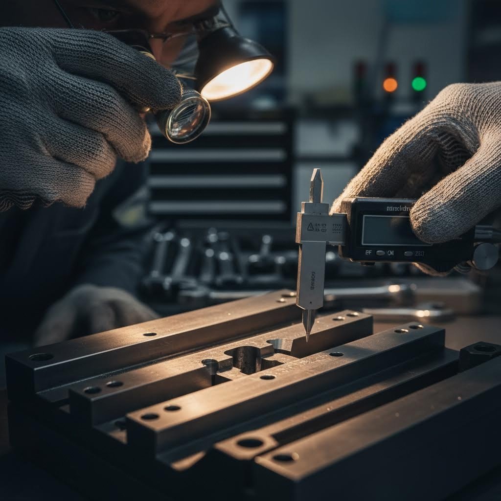
Štampų projektavimo principai ir inžineriniai aspektai
Pasirinkus tinkamus medžiagų, kyla kitas iššūkis: jūsų detalės konceptą paversti gamybai paruoštu štampavimo šablonu. Būtent čia inžinerinė patirtis atskiria vidutiniškus įrankius nuo tikslaus įrangos, galinčios pagaminti milijonus identiškų detalių. Šablono projektavimo procesas apima daug daugiau nei tiesiog kaverno sukūrimą, atitinkantį jūsų detalės formą – reikia numatyti, kaip lakštinis metalas tekės, išsitiesins ir grįš į pradinę padėtį formuojant.
Metalinio štampavimo šablonų projektavimas vyksta pagal struktūruotą metodiką, kuri prasideda nuo pradinės įgyvendinamumo analizės ir baigiasi patvirtintais, gamybai paruoštais įrankiais. Praleidus bet kurį žingsnį, kyla pavojus brangiam pakartotiniam darbui, kai kietasis įrankių plienas jau yra presuose. Panagrinėkime nuoseklias fazes, kurias profesionalūs šablonų projektuotojai laiko.
Inžinerinės principai, leidžiantys sukurti veiksmingą šablonų projektą
Prieš pradedant bet kokią CAD darbų veiklą, patyrę inžinieriai atlieka išsamią detalių brėžinių analizę. Pag according to U-Need Precision Manufacturing, šis pirmasis kontrolės etapas nustato, ar štampavimas yra tinkamiausias ir ekonomiškiausias gamybos metodas jūsų konkrečiai geometrijai ir tikslumo reikalavimams.
- Detalių brėžinių analizė ir įgyvendinamumo tyrimas: Inžinieriai vertina kritines matmenų reikšmes, medžiagos specifikacijas ir tikslumo reikalavimus, kad patvirtintų štampavimo galimybę. Jie nustato potencialius sunkumus, pvz., gilų štampavimą, aštrius kampus ar plonas sienas, kurie gali sukelti formavimo problemas.
- Juostos išdėstymo kūrimas: Progresyviems ir perduodamiems lakštinių metalų šablonams šiame etape nustatomas operacijų seka įrankyje. Išdėstymas nustato medžiagos naudojimą, stoties tarpus ir pjovimo bei formavimo operacijų tvarką.
- Komponentų projektavimas ir 3D modeliavimas: Detali inžinerinė kaltukų, šablonų įdėklų, atskyrimo plokščių ir vedamųjų komponentų projektavimas. Kiekvienam elementui nustatomos tikslūs reikalavimai dėl medžiagos, kietumo ir matmenų tikslumo.
- CAE modeliavimas ir patvirtinimas: Virtualus bandymas numato medžiagos elgesį dar prieš supjaustant bet kurį plieną, ankstyvai nustatydamas galimus gedimus, kai pakeitimai kainuoja nieko.
- Detalių brėžiniai ir gamybos išleidimas: Galutinė 2D dokumentacija apima visą konstrukciją gamybai, įskaitant surinkimo sekas ir kritinius tikrinimo taškus.
Juostos išdėstymo optimizavimui štampavimo šablonų projektavime reikia skirti ypatingą dėmesį. Galima tai įsivaizduoti kaip šokio režisūrą, kur metalinė juosta juda per šabloną tiksliais žingsniais. Pagrindiniai aspektai yra:
- Žingsnio atstumas: Tikslus atstumas, kurį juosta paslenkama kiekvienu spaudimo ciklu – per trumpas žingsnis sukelia medžiagos švaistymą, o per ilgas – pažeidžia registravimo tikslumą
- Operacijų sekomos nustatymas: Operacijų tvarkos nustatymas taip, kad būtų sumažintas juostos apkrova, vienu metu išlaikant matmeninį tikslumą
- Nešančiosios juostos konstrukcija: Medžiaga, jungianti detalės dalis per šabloną, turi būti pakankamai stipri, kad patikimai judėtų, tačiau ji turi būti išdėstyta taip, kad būtų sumažintas šukos kiekis
- Vadovaujančiųjų skylių vieta: Registracijos funkcijos, užtikrinančios tikslų lygiavimą kiekviename poste
Medžiagos srauto analizė tiria, kaip lakštinis metalas juda formavimo operacijų metu. Kai lenkiate arba traukiate metalą, jis nesulankstoma paprasčiausiai – kai kuriose vietose jis išsitempia, o kitose suspaudžiamas. Šių srautų modelių supratimas leidžia konstruktoriams strategiškai išdėstyti medžiagą, išvengiant pernelyg plonėjimo, kuris sukelia plyšius, ar pernelyg storėjimo, kuris sukelia raukšles.
Atšokimo kompensavimas yra vienas sudėtingiausių lakštinio metalo štampavimo šablonų projektavimo aspektų. Kai formavimo slėgis nuima, metalas dalinai grįžta į pradinę formą. Šio atšokimo dydis priklauso nuo medžiagos rūšies, storio, lenkimo spindulio ir grūdų krypties. Patyrę konstruktoriai specialiai į savo įrankių geometriją įtraukia „perlenkimą“, kad galutinis detalės atšokimas būtų tikslus ir detalė įgytų reikiamus matmenis.
Tolerancijų kaupimosi valdymas užtikrina, kad kumuliacinės nuokrypos per kelias operacijas neviršytų galutinio gaminio techninių reikalavimų. Kiekviena stotis įveda mažas nuokrypas – atskirai jos yra priimtinos, tačiau susikaupus gali sukelti problemas. Projektuotojai kiekvienai operacijai priskiria tolerancijų biudžetą, kad užtikrintų, jog baigtinis gaminys atitiktų brėžinyje nustatytus reikalavimus.
Nuo CAD iki gamybai paruošto įrankio
Šiuolaikinis štampavimo šablonų projektavimas labai pasiremia kompiuteriu paremta inžinerija (CAE) ir baigtinių elementų analize (FEA), kurios naudojamos projektų patvirtinimui prieš fizinių įrankių gamybą. Kaip Engineering Technology Associates aiškina, FEA veikia padalydama konstrukciją į mažesnių elementų tinklą, o po to taikydama matematines lygtis, kad būtų analizuojamas jos elgesys įvairiomis apkrovos sąlygomis.
Įsivaizduokite sudėtingos lakštinio metalo šablonų virtualų bandymą: programinė įranga tiksliai numato, kur medžiaga plonės traukimo metu, kur gali susidaryti raukšlės ir kiek reikės laukti atšokimo po formavimo. Šis virtualus patvirtinimas pašalina brangų bandymų ir klaidų metodą, kuriam anksčiau reikėdavo kelių fizinių prototipų.
CAE modeliavimo galimybės apima:
- Formavimo analizę: Medžiagos tekėjimo, plonėjimo ir galimo plyšimo numatymas giliosiomis traukomis bei sudėtingomis formomis
- Springback prognoza: Matmenų pokyčių po formavimo slėgio nuėmimo apskaičiavimas, leidžiantis kompensuoti šablonų geometriją
- Iškirpų optimizavimas: Optimalaus plokščiojo piešinio formos ir dydžio nustatymas, kad būtų sumažinta medžiagos š waste ir tuo pat metu užtikrinta visiška detalės suformavimas
- Įrankio paviršiaus projektavimą: Paviršių, kontroliuojančių medžiagos tekėjimą į šablonų ertmę, optimizavimas
- Ištvermės gyvavimo trukmės prognozavimas: Diegiamų šablonų komponentų ciklų skaičiaus įvertinimas iki pirmojo techninės priežiūros reikalavimo
Apėjimo įpjovos lakštinių metalų štampavimo šablonuose turi tam tikrą paskirtį, kurią daugelis mokymo išteklių praleidžia. Šios strategiškai išdėstytos išpjovos juostoje leidžia medžiagai tekėti formavimo operacijų metu, neiškreipiant gretimų elementų. Kai formavimo stotis traukia medžiagą į šabloną, ji traukia ją iš aplinkinių sričių. Be apėjimo įpjovų šis traukimo veiksmas gali iškreipti anksčiau suformuotus elementus arba perplėšti nešančiąją juostą.
CAD, CAE ir CAM programinės įrangos integracija sukuria tai, ką inžinieriai vadinama „skaitmenine grandine“ – nuolatinis duomenų srautas nuo pradinės idėjos iki baigtos įrankių gamybos. Naudojant platformas, tokias kaip AutoForm ar DYNAFORM, dizaineriai greitai atlieka pakartotinius projektavimo ciklus virtualioje aplinkoje. Pagal U-Need inžinerinės komandos teigimą, šis modeliavimo etapas sumažina projektų riziką, sutrumpina realių bandymų laikotarpius ir žymiai padidina pirmojo bandymo sėkmės rodiklį.
Kodėl tai svarbu jūsų gamybai? Kiekvienas simuliacijoje aptiktas ciklas sutaupo savaites laiko fiziniams pakeitimams ir tūkstančius dolerių perdaromųjų darbų sąnaudoms. Lakštinio metalo šablonas, kuris teisingai patvirtinamas simuliacijoje, dažniausiai pasiečia gamybai paruoštos būklės būseną per žymiai trumpesnį laiką lyginant su tradiciniais bandymų ir klaidų metodais.
Šių šablonų projektavimo principų supratimas keičia tai, kaip įvertinate įrankių tiekėjus ir bendraujate su inžinerinėmis komandomis. Dabar jūs esate pasiruošę aptarti juostos išdėstymą, grįžtamojo deformavimosi kompensavimo strategijas ir simuliacijos patvirtinimą – tai pokalbiai, kurie lemia geresnius įrankius ir mažiau netikėtumų gamybos metu. Šis inžinerinis pagrindas parengia sąlygas suprasti tikrąjį lakštinio metalo štampavimo gamybos procesą, kuriame jūsų rūpestingai suprojektuoti šablonai transformuoja žaliavas į baigtus gaminius.
Lakštinio metalo štampavimo gamybos proceso paaiškinimas
Jūsų šablonas yra suprojektuotas, patvirtintas modeliavimo būdu ir paruoštas gamybai. Bet kas iš tikrųjų vyksta, kai metalas susiduria su presu? Supratimas apie gamybos štampavimo procesą nuo žaliavos ritės iki baigto gaminio paaiškina, kodėl tikslumas kiekviename etape lemia galutinį kokybės rezultatą. Šios žinios paverčia jus ne aktyviu pirkėju, o informuotu partneriu, kuris geba nustatyti problemas ir optimizuoti gamybos efektyvumą.
Metalo štampavimo procesas apima mechaninę jėgą, tikslų laikymą ir atidžiai kontroliuojamą medžiagos srautą. Ar paleidžiate mažą stendinį presą, kurio naudingoji apkrova – penki tonos, ar milžinišką tiesiaeigį presą, kurio naudingoji apkrova matuojama tūkstančiais tonų, pagrindinis ciklas lieka nepakitęs – tačiau masto padidėjimas dramatiškai padidina riziką.
Štampavimo ciklo analizė
Kiekvienas štampuojamas detalės pradžią pradedą kaip plokščias lakštinis metalas, dažniausiai tiekiamas iš ritės. Pagal Gamybos inžinerijos draugiją rulonų apdorojimas žymiai padidina štampavimo efektyvumą, nes gamyba tęsiamasi be pertraukų nuolatine tiekimo sistema.
Štampavimo procesas vyksta žingsnis po žingsnio taip:
- Rulonų atvyniojimas ir išlyginimas: Išvyniojimo būgnai palaiko ir atvynioja ruloninę medžiagą. Medžiaga praeina per išlyginamąsias ritinėles, kurios pašalina įtempimą (kreivumą), susidariusį dėl vyniojimo, ir tiekia plokščią medžiagą į presą.
- Maitinimas: Automatiniai tiekimo mechanizmai – naudodami slydimo, ritinėlių ar griebikų sistemas – kiekviename preso cikle tiksliai pastumia juostą tam tikru atstumu. Skaitmeniškai valdomi servotiekėjai leidžia realizuoti sudėtingus tiekimo modelius, tokius kaip išlinkimų (joggle), žigzago ir grįžtamojo (shuttle) tiekimas.
- Formavimo operacijos: Preso stovas nusileidžia, įspaudžiant štampus į šablonų ertmes. Kirpimas, lenkimas, traškinimas ir formavimas vyksta per dešimtųjų sekundės dalis.
- Detalės išstūmimas: Išstumiamieji mechanizmai nuima suformuotus gaminius nuo štampų. Galutiniai komponentai krenta per šabloną arba perduodami į kitą stotį.
- Atliekų apdorojimas: Iškirptos detalės (slugs) ir kraštų atliekos išmetamos specialiais mechanizmais, dažniausiai preso veikiamais arba atskirai varomais.
Spaudimo gamyboje esminis trikampis susideda iš spaustuvų naudingosios apkrovos, įtempimo dažnio ir šablonų reikalavimų. Metalinių spaustuvų galia labai skiriasi – nuo paprastų stalų vienetų, kurie sukuria penkis tonas, iki milžiniškų įrengimų, kurių naudingoji apkrova matuojama tūkstančiais tonų. Spaustuvų greitis svyruoja nuo 10 iki 18 įtempimų per minutę sunkiajam formavimui ir iki 1400 įtempimų per minutę mažiems, didelės apimties detalėms.
Esminiai technologiniai parametrai, kurie tiesiogiai veikia jūsų detalių kokybę, yra:
- Jėgos talpa: Maksimali naudingoji apkrova, kurią galima pasiekti nurodytu atstumu virš įtempimo žemiausiosios padėties, išreiškiama tonomis arba kilonjutonais
- Įtempimo dažnis: Ciklai per minutę – didesnis greitis padidina gamybą, tačiau reikalauja patikimesnių šablonų ir tikslaus medžiagos tiekimo
- Uždaromoji aukštis: Atstumas tarp pagrindo ir stūmoklio įtempimo žemiausiojoje padėtyje, nulemia maksimalų šablono aukštį
- Padavimo tikslumas: Vadovaujančių žymų registracija ir tiekimo tikslumas, dažniausiai matuojamas tūkstantosiomis colio dalimis
- Blanko laikiklio jėga: Spaudimas, kontroliuojantis medžiagos tekėjimą traukimo operacijų metu, yra esminis raukšlių ir plyšių prevencijai
- Teršalų padavimas: Nuosekli taikymo technika, neleidžianti sukibti paviršiams ir mažinanti formavimo jėgas
Presų pasirinkimas tiesiogiai veikia tai, ko galite pasiekti su savo šablonais. Mechaniniai presai suteikia maksimalią jėgą arti įstumimo eigos pabaigos – tai idealu išpjaustymui ir skylėms darymui. Hidrauliniai presai suteikia pilną jėgą visoje įstumimo eigoje, todėl jie yra pranašesni giliems trapecijos formavimams ir formavimo operacijoms, kuriose reikia stiprių jėgų įstumimo eigos viršuje.
Tikslumo standartai šiuolaikinėse štampavimo operacijose
Kai nurodote leistinąsias nuokrypas savo detalės brėžinyje, štampavimo procesas turi jas užtikrinti. Tačiau pasiekiamas tikslumas žymiai skiriasi priklausomai nuo šablono tipo, medžiagos ir preso charakteristikų.
Bendrosios leistinos nuokrypos gamybos štampavime:
- Eilinės formos: Paprastai laikoma ±0,001–±0,005 colio tikslumas kritinėse matmenų vietose, o tikslūs šablonai gali užtikrinti dar griežtesnes nuokrypas
- Perleidžiamos formos: Panašus tikslumo potencialas, tačiau detalės pernešimas tarp stoties įveda papildomų kitimo šaltinių
- Sudėtinės formos: Dažnai pasiekiamos mažiausios leistinos nuokrypos dėl vienu metu vykdomų operacijų, kurios pašalina registravimo klaidas tarp stotyčių
- Paviršiaus išdėstymas: Kintama nuo 32 iki 125 mikrūdžių Ra priklausomai nuo štampavimo įrankio būklės, medžiagos ir tepalo
Kelios aplinkybės veikia pasiekiamą tikslumą jūsų štampavimo procese:
- Preso standumas: Tiesiaeiliai presai pašalina kampinį išlinkimą, kuris būdingas plyšio tipo konstrukcijoms, tiesiogiai gerindami detalės tikslumą ir štampavimo įrankio tarnavimo laiką
- Formos centravimas: Teisingai sureguliuoti gib’ai užtikrina lygiagretumą ir statumą visame ėjime
- Medžiagos vientisumas: Storis, kietumo svyravimai ir grūdelių kryptis visi veikia galutinius matmenis
- Temperatūros stabilumas: Ilgoje gamybos serijoje temperatūros padidėjimas gali pakeisti matmenis už leistinų nuokrypų ribų
- Įrankių nusidėvėjimas: Kirpamieji kraštai palaipsniui bluntėja, kas veikia burbulų susidarymą ir matmeninį tikslumą
Šių tikslumo pagrindų supratimas tiesiogiai susijęs su kokybės rezultatais. Presas, dirbantis 1800 smūgių per minutę — taip, tai po 30 detalių per sekundę — reikalauja visiškai nuoseklaus medžiagos tiekimo, tobulos štampavimo įrankių išdėstymo ir patikimų įrankių medžiagų. Nepakankamai kontroliuojant bet kurį iš šių elementų, atliekų kiekis didėja, o vėliau padidėja klientų grąžinimų skaičius.
Gamybos štampavimo procesas atspindi dešimtmečius tobulintos inžinerijos, kur mechaninis tikslumas susiliečia su medžiagų mokslo pasiekimais, vykstant tiksliai kontroliuojamai jėgos ir laiko sąveikai. Šių pagrindų įvaldymas leidžia optimizuoti jūsų veiklą — tačiau net geriausiai suprojektuotiems procesams reikia nuolatinio dėmesio. Būtent čia įrankių priežiūros ir gedimų šalinimo supratimas tampa būtinas jūsų įrankių investicijoms apsaugoti.
Įrankių priežiūra ir gedimų šalinimas, kad būtų pratęsta jų tarnavimo trukmė
Jūsų štampavimo šablonas yra reikšmingas investicijos objektas – dažnai sudėtingoms progresyvioms įrankių sistemoms išleidžiama dešimtys tūkstančių dolerių. Tačiau daugelis gamintojų prižiūrėjimą traktuoja kaip antrarūšį uždavinį ir veikia reaguodami į gedimus, o ne juos užkertant kelią. Šis reaktyvus požiūris padidina sąnaudas dėl neplanuotos įrangos sustojimų, atmestų detalių ir skubios remonto paslaugos, kurių būtų galima išvengti.
Štai tikroji padėtis: netinkamas šablonų prižiūrėjimas ne tik sutrumpina įrankių tarnavimo laiką. Pagal The Phoenix Group , tai sukelia kokybės defektus gamybos metu, padidina rūšiavimo sąnaudas, didina tikimybę išsiųsti defektines dalis ir kelia pavojų brangiai kainuojančioms priverstinėms apribojimo priemonėms. Kai šablonų apdorojimo problemos kyla viduryje serijos, jūs patinkate blogiausiuose abiejų pasaulių deriniuose – prarandamas preso laikas, atliekant laikinąsias modifikacijas „po stūmoklio“, taip pat reikia nuolatinių pataisymų prieš kitą gamybos ciklą. Tai dvigubai padidina prižiūrėjimo sąnaudas.
Suprantant dažniausiai pasitaikančias štampavimo šablonų gedimų priežastis ir įdiegiant sistemingą profilaktinę priežiūrą, jūsų veikla iš „gaisrų gesinimo“ režimo pereina prie strateginio valdymo. Panagrinėkime problemas, su kuriomis susidursite, ir kaip jas išspręsti dar prieš joms pasunkėjant.
Bendrų šablonų gedimų diagnozavimas prieš jų pasunkėjimą
Kai šablonas pradeda gaminti abejotinus detalių gamybos rezultatus, patyrę operatoriai pastebi įspėjamuosius požymius dar prieš visiško gedimo įvykimą. Kokia iššūkio esmė? Nustatyti pagrindines priežastis, o ne tik šalinti simptomus. Remiantis DGMF Mold Clamps trikčių šalinimo duomenimis, dauguma štampavimo šablonų problemų kyla iš kelių pagrindinių priežasčių.
| Problemos tipas | Pagrindinės priežastys | Įspėjimo ženklai | Taisomieji sprendimai |
|---|---|---|---|
| Sukibimas | Nepakankamas tepimas; šablono/medžiagos nesuderinamumas; per didelis slėgis; nepakankamas šablono paviršiaus apdirbimas | Medžiagos kaupimasis ant kaltauko ar šablono paviršiaus; įbrėžtos detalės; didėjantys formavimo jėgos; netolygus štampuotų detalių paviršiaus apdirbimas | Gerinti tepalo padavimą; taikyti TiCN ar kitas priešsuliejimo dangas; šlifuoti štampų paviršius; reguliuoti tarpus; apsvarstyti kitą štampo medžiagą |
| Apskeldimas | Per didelis kietumas be pakankamos smūgiui atsparios savybės; smūginis apkrovimas; netinkamas termoapdorojimas; nuovargis dėl ilgalaikio naudojimo | Maži fragmentai trūksta pjovimo kraštų; įbrėžimai štampuotose detalėse; nepastovus pjovimo kokybės lygis; matomi kraštų pažeidimai tikrinant | Pasirinkti atsparesnės rūšies įrankių plieną (S7, A2); patikrinti termoapdorojimo specifikacijas; sumažinti smūginį apkrovimą; įdiegti profilaktinės kraštų priežiūros grafiką |
| Nesuderinimas | Stankio bokšto konstrukcijos ar apdirbimo tikslumo problemos; susidėvėję orientaciniai žiedai; netinkama štampų montavimas; ilgalaikis susidėvėjimas montavimo paviršiuose | Netolygus kalno susidėvėjimas; detalės su nepastoviais matmenimis; per didelis triukšmas veikiant; matomi tarpų pokyčiai tarp kalno ir štampo | Naudoti centravimo strypą, kad patikrintumėte ir sureguliuotumėte bokšto centravimą; pakeisti susidėvėjusius orientacinius žiedus; patikrinti montavimo kryptį; įdiegti visiškai orientuojamus štampus |
| Burr formacija | Bluntūs pjovimo kraštai; per didelis kalapso ir matricos tarpas; netinkama medžiagos parinktis; išnaudoti ar pažeisti matricos komponentai | Matomi šukutės pjovimo kraštuose; šukutės aukštis didėja gamybos ciklo metu; detalės neatitinka kraštų kokybės specifikacijų | Patrinkti arba pakeisti pjovimo komponentus; sureguliuoti tarpus tinkama procentine dalimi nuo medžiagos storio; nustatyti reguliarius atnaujinimo (perdirbimo) intervalus |
| Šukutės išlaikymas | Per mažas matricos tarpas; vakuumas, susidarantis traukiant kalapsą; išnaudotos ar pažeistos šukutės išleidimo vietos; netinkamas matricos ventiliavimas | Šukutės pakyla kartu su kalapsu; pakartotiniai smūgiai, sukeliantys matricos pažeidimus; nestabili detalės kokybė; matomos šukutės matricoje | Patikrinti ir sureguliuoti matricos tarpus; įdiegti vakuumo išleidimo elementus; pagerinti šukutės kritimo kampą; įdiegti šukutės aptikimo sistemas |
| Nestabilus ausėjimas | Viršutinės ir apatinės sukamosios lentos nesutapimas; formos konstrukcijos ar tikslumo problemos; vedamųjų įvorės tikslumo trūkumai; netinkami tarpai | Kai kuriose matricos vietose stebimi didesni bruožai; tam tikrose pozicijose ausėjimas vyksta greičiau; detalėse pastebima matmenų kitimų priklausomai nuo pozicijos | Reguliariai tikrinkite sukabintuvą su mandreliu; keiskite orientacinius įdėklus; pasirinkite tinkamą žymeklio tarpą pagal medžiagą; naudokite visiškai orientuojančią įrankių sistemą |
Pastebėkite, kiek problemų kyla dėl nesutapimo? Tai ypač ryšku plonose, siaurose stačiakampėse štampavimo šablonų konfigūracijose. Sprendimas reikalauja sisteminio požiūrio: reguliariai tikrinkite bokšto nustatymą, prieš tai, kol susidėvėję komponentai sukels antrines žalas, keiskite juos ir pasirinkite įrankių konstrukcijas, kurios visą stumdymo eigą užtikrintų maksimalų orientavimą.
Profilaktinė priežiūra, padedanti pratęsti šablonų tarnavimo laiką
Reaktyvi techninė priežiūra yra brangi. Kiekvienas neplanuotas šablonų remontas nutraukia gamybą, priverčia skubiai planuoti darbus ir dažnai lemia suboptimalius sprendimus, priemtuosius laiko trūkumo sąlygomis.
Veiksminga šablonų priežiūra reiškia sistemingą šablonų tikrinimo, remonto ir optimizavimo procesą, vykdomą pagal nustatytas kasdienio priežiūros procedūras. Tai apima reguliarius tikrinimus siekiant nustatyti dilimą, pažeidimus ar defektus, o po to – būtinus remontus ir reguliavimus, kol problemos nepasidaro rimtesnės.
Jūsų profilaktinės priežiūros programa turėtų apimti šiuos būtinus elementus:
- Tikrinimo po gamybos ciklo protokolas: Kiekvieno gamybos ciklo baigimo metu, prieš šabloną sandėliuojant, išnagrinėkite visus pjovimo kraštus, formavimo paviršius ir lygiavimo komponentus
- Valymo procedūros: Pašalinkite visą tepalo likučius, metalo daleles ir kitą šiukšlį, kurie gali sukelti koroziją ar trukdyti tinkamai šablono veikimui
- Tepimo patikrinimas: Įsitikinkite, kad visi vedamieji žymekliai, įvorės ir judantys komponentai yra tinkamai sutepami
- Pjovimo kraštų įvertinimas: Išmatuokite kraštų būklę ir numatykite pergrindimą dar prieš tai, kai dilimas pradės neigiamai veikti gaminio kokybę
- Išlyginimo patikrinimas: Naudokite matavimo žymeklius arba bandymo juosteles, kad patvirtintumėte tinkamą smigalų ir šablonų vienodą išdėstymą
- Spyruoklių ir slėgio komponentų tikrinimas: Patikrinkite, ar šalinamieji įtaisai, plokščių laikymo įtaisai ir spaudimo padėklai sukuria tinkamą jėgą
- Dokumentacija: Įrašykite visas pastebėjimų, matavimų ir atliktų darbų žymas trendų analizei
Techninės priežiūros darbų prioritetų nustatymui reikia sisteminio požiūrio. „Phoenix Group“ rekomenduoja sprendimų medį, kuriame prioritetų nustatymas remiamas gamybos poveikiu:
- Aukščiausias prioritetas: Gamybos nevykdymo sąlygos – gamyba negali būti vykdoma dėl sugadintų šablonų arba kokybės nepriėmimo, dėl ko detalės tampa nepelningos
- Antras prioritetas: Gamybos našumo ar kokybės gerinimo poreikiai – aukštesni nei pageidautini atmetimo rodikliai, neformalūs klientų skundai ar atsitiktiniai formavimo nesėkmės atvejai
- Trečiasis prioritetas: Nuolatinio tobulėjimo veiklos, įskaitant ribotų formavimo galimybių įtempimo būsenos šalinimą, medžiagų taupymo įdiegimą ar inžinerinių pokyčių įgyvendinimą
Darbo užsakymų sistemos sudaro veiksmingos šablonų priežiūros pagrindą. Kiekvienas užklausa turi dokumentuoti pagrindinę problemą, žingsnius, kurie buvo atlikti siekiant ją išspręsti, ir bet kokias nepatikrintas pradines sąlygas, kurios buvo ištaisytos. Baigti darbo užsakymai sukuria istoriją, kuri padeda prognozuoti būsimus priežiūros poreikius ir neleidžia pasikartoti toms pačioms problemoms.
Štai praktinė įžvalga, kurią daugelis gamybos įmonių praleidžia: duomenys iš ankstesnių darbo užsakymų vienam šablonui gali pagerinti profilaktinės priežiūros planavimą simetriniams detalių elementams arba panašiems komponentams, priklausantiems tam pačiam detalės šeimynai. Jei jūsų kairės pusės durų vidinė dalis rodo tam tikrus dėvėjimosi modelius po 50 000 ciklų, labai tikėtina, kad tokį pat dėvėjimosi modelį parodys ir dešinės pusės versija. Šio modelio pagrindu vykdomas aktyvus planavimas visiškai išvengia antrojo gedimo.
Štampavimo šablonų apdirbimas atgal iki techninių reikalavimų—ar tai būtų šlifavimas, elektroerosinis apdirbimas (EDM) arba įprastas apdirbimas—sudaro reikšmingą priežiūros veiklos dalį. Aiškiai nustatytos kriterijų sistemos, kada šablonus reikia peršlifuoti, o kada keisti, padeda išvengti tiek per ankstyvo komponentų keitimo (pinigų švaistymo), tiek pažeistų įrankių naudojimo (detalių švaistymo ir katastrofiško verslo nutraukimo rizikos).
Sistemingos priežiūros investicijos duoda naudos ne tik padidindamos šablonų tarnavimo laiką. Jos sumažina kokybės defektus, neleidžia netikėtoms prastovoms ir suteikia duomenis, kurie pagerina būsimų šablonų projektavimą. Kai jūsų priežiūros protokolai jau įdiegti, jūs esate pasiruošę įvertinti potencialius štampavimo partnerius remdamiesi tuo, kaip gerai jų praktika atitinka šiuos patikrintus principus.
Tinkamo štampavimo šablono partnerio parinkimas jūsų gamybos poreikiams
Jūs suprantate štampavimo technologijas, medžiagas, projektavimo principus ir priežiūros reikalavimus. Dabar atėjo sprendimo priėmimo metas, kuris viską sujungia: reikia pasirinkti štampavimo partnerį, kuris iš tikrųjų galėtų įvykdyti visus šiuos techninius reikalavimus. Tai nėra tik žemiausios kainos pasiūlymo paieška – tai reiškia, kad reikia nustatyti specialius metalo štampavimo paslaugų teikėjus, kurie apsaugotų jūsų gamybos grafiką, kokybės standartus ir pelningumą, galbūt milijonams detalių.
Neteisingas pasirinkimas čia sukelia grandininį problemų efektą. Praleisti pristatymai sustabdo jūsų surinkimo linijas. Kokybės problemos priverčia atlikti brangius rūšiavimo veiksmus. Inžinerinės spragos lemia kelis šablonų koregavimo ciklus, kurie peržengia projekto biudžetą. Pagal Penn United Technologies priklausomai nuo pirkimo sprendimo, priimto tik remiantis pateikta kaina, gali būti pasiektas bendras nepasitenkinimas tiekėjo veikla ar net katastrofiški rezultatai.
Taigi kaip atskirti kvalifikuotus štampavimo šablonų gamintojus nuo tų, kurie sukels problemų?
Sertifikavimo standartai, kurie rodo kokybę
Sertifikatai – tai ne tik popieriai: jie atstovauja patikrintoms sistemoms, kurios aptinka problemas dar prieš jas pasiekiant jūsų gamybos liniją. Įvertindami individualius metalo štampavimo gamintojus, šie dokumentai rodo reikšmingą kokybės užtikrinimo infrastruktūrą:
- IATF 16949 sertifikavimas: Pagal Xometry, ši automobilių pramonei skirta kokybės valdymo sistema remiasi ISO 9001 pagrindais, tačiau papildoma automobilių gamybai specialiai sukurtomis sąlygomis. IATF 16949 sertifikavimas reiškia, kad organizacija atitinka griežtus reikalavimus, įrodydama savo gebėjimą ir įsipareigojimą riboti defektus ir mažinti š waste. Jei pirkiate automobilių štampavimo komponentus, šis sertifikatas yra beveik privalomas.
- ISO 9001 sertifikavimas: Pagrindinė kokybės valdymo sistema, užtikrinanti dokumentuotus procesus, nuoseklius rezultatus ir nuolatinio tobulėjimo sistemas. Tai sudaro bazinį apsaugos sluoksnį, kuris garantuoja, kad egzistuoja kontrolės procesai.
- Privalomieji sertifikatai pagal pramonės šaką: Aviacijos (AS9100), medicinos prietaisų (ISO 13485) ar gynybos srityje taikomos sertifikacijos rodo specializuotas galimybes ir atitiktį sektoriui būdingiems reikalavimams.
Tačiau vien tik sertifikatai dar neįrodo sėkmės. Kaip pabrėžia Penn United, geriausias būdas įvertinti dėmesį procesų kontrolės klausimui – tai aplankyti tiekėją ir pažvelgti, kaip veikia jų kokybės sistema. Paprašykite parodyti kontrolės planes, supraskite, kaip dirba kokybės technikai, ir įvertinkite jų investicijas į tikrinimo įrangą.
Inžinerijos ir prototipavimo gebėjimų vertinimas
Be sertifikatų, metalinių štampavimo šablonų gamintojų techninės galimybės tiesiogiai lemia, ar jūsų projektas pavyks iš karto ar reikės brangios pakartotinės korekcijos. Štai išsami vertinimo schema:
- Šablono projektavimo ir gamybos galimybė: Tiekimo šaltinis, kuris gali projektuoti ir gaminti tikslųjį štampavimo šabloną patalpose, būtinai bus daug kvalifikuesnis nei tas, kuris šias funkcijas perduoda įšalintiems tiekėjams. Jie supranta, kokios savybės ir stotys užtikrina maksimalią efektyvumą ir kokybę štampavimo operacijų metu.
- CAE modeliavimo ištekliai: Tiekėjai, naudojantys baigtinės elementų analizę ir formavimo modeliavimą, virtualiai aptinka problemas – dar prieš tai, kai brangūs fiziniai įrankiai būtų pagaminti. Ši galimybė žymiai sumažina pirmųjų pavyzdžių nesėkmes ir sutrumpina laiką iki gamybos pradžios.
- Prototipavimo greitis: Kiek greitai tiekėjas gali pagaminti pavyzdinius detalių gabalus patvirtinimui? Greitojo prototipavimo galimybė – kuri matuojama dienomis, o ne savaitėmis – pagreitina jūsų plėtros grafiką ir leidžia greičiau atlikti pakartotinius derinimus.
- Pirmojo praeities patvirtinimo rodiklis: Šis rodiklis atskleidžia inžinerinės veiklos efektyvumą. Tie tiekėjai, kurie pasiekia 90 % ar daugiau pirmojo praeities patvirtinimo rodiklį, demonstruoja subrendusius projektavimo procesus, kurie neleidžia brangaus pakartotinio darbo.
- Gamybos apimties talpa: Įsitikinkite, kad tiekėjas gali padidinti gamybą nuo pirmųjų pavyzdžių kiekių iki visos gamybos apimties be kokybės sumažėjimo ar pristatymo problemų.
- Trikties šalinimo ekspertizė: Tiekėjas, kuris įgudęs kurti ir tobulinti štampavimo šablonus, turi papildomą pranašumą – gebėjimą operatyviai šalinti neplanuotas štampavimo problemas, kas ypač svarbu užtikrinant nepriekaištingą gamybą kilus netikėtoms situacijoms.
- Papildomos operacijos: Tiekėjai, siūlantys valymo, elektrolitinio metalinimo, supakavimo ar surinkimo paslaugas, supaprastina jūsų tiekimo grandinę ir sumažina logistikos sudėtingumą.
Atsižvelkite į tai, kokią praktinę įtaką daro prototipavimo greitis ir inžinerinė branda. Tikslaus štampavimo šablonų ir detalių gamybos srityje partneris kaip Shaoyi pateikia pavyzdį to, ko reikėtų ieškoti: IATF 16949 sertifikavimas rodo automobilių pramonės kokybės valdymo sistemas, o jų CAE modeliavimo galimybės padeda išvengti konstrukcinių problemų dar prieš pradedant fizinių šablonų gamybą. Jų 5 dienų greitojo prototipavimo galimybė sutrumpina plėtojimo terminus, o 93 % pirmojo patvirtinimo rodiklis rodo subrendusias inžinerines procedūras, kurios sumažina brangius pakartotinius derinimus.
Įvertindami specializuotų metalo štampuojamųjų detalių tiekėjus, nedėkite šonu, atrodytų mažai reikšmingų veiksnių, kurie iš tikrųjų rodo ilgalaikio partnerystės kokybę:
- Dėmesys detalėms: Atkreipkite dėmesį į tiekėjo elgesį kainų pasiūlymo parengimo metu. Tiekejas, kuris užduoda išsamius klausimus apie detalės kokybę, pagrindines savybes ir nuokrypius, dažniausiai gamybos metu peržengia dėmesio į smulkmenas ribas.
- Pristatymo įvykdymo įrašai: Jei tiekėjas oficialiai nekontroliuoja laiku pristatytų užsakymų rodiklio, pasirinkite kitą tiekėją. Šis rodiklis parodo, ar egzistuoja tinkamos sistemos realistiškoms kainų pasiūlymų terminų įvertinimui ir jų faktiniam laikymuisi.
- Papildomos įrankių aptarimo dalis: Geras tiekėjas siūlo iš anksto aptarti atsarginių įrankių klausimą, kad būtų maksimaliai padidintas sėkmės tikimybė. Ši sąnauda turėtų būti įtraukta palyginant pasiūlymus – tiekėjai, kurie ją ignoruoja, gali sukelti gamybos pertraukas.
- Šablonų priežiūros programa: Tiekėjai, siūlantys oficialius techninės priežiūros programas, maksimaliai padidina šablonų tarnavimo laiką ir optimizuoja jūsų bendrą gyvavimo ciklo sąnaudas. Paklauskite apie patikrinimų grafikus, komponentų keitimo protokolus bei sinchronizavimo procedūras.
Vertinimo procesas trunka laiką – tačiau tai yra protingai investuotas laikas. Skubėjimas pasirinkti tiekėją tik remiantis žemiausia kaina dažnai veda prie didžiausių bendrų sąnaudų, kai kaupiasi kokybės problemos, delsos ir pakartotinio darbo sąnaudos. Taikykite struktūruotą požiūrį: patikrinkite sertifikatus, įvertinkite inžinerines galimybes, patikrinkite gamybos pajėgumus ir įvertinkite tiekėjo pasiryžimą teikti partnerystės lygio paslaugas.
Kai jūsų tiekėjų atrankos sistema jau įdiegta, jūs esate pasiruošę priimti informuotus sprendimus, kurie apsaugos jūsų gamybos kokybę ir laiko grafiką. Tačiau veiksmingas bendravimas su bet kuriuo štampavimo partneriu reikalauja bendros terminologijos – todėl pereiname prie esminių terminų, kuriuos profesionalai naudoja kalbėdami apie metalo štampavimą ir šablonų (štampų) veikimą.

Metalo štampavimo ir šablonų (štampų) terminų žodynas
Ar kada nors esate linktelėję sutikdami su tiekėju, nors iš tikrųjų nežinojote, kas yra „ištraukimo santykis“ ar „šukos išlaikymas“? Jūs nesate vienintelis. Štampavimo ir šablonų (štampų) gamybos specializuota terminologija kelia kliūtis tarp specialistų, kurie kitu atveju galėtų veiksmingai bendradarbiauti. Ar jūs būtumėte inžinierius, nurodantis detalių specifikacijas, pirkėjas, vertinantis tiekėjus, ar technikas, aptinkantis gedimų priežastis, – šios terminologijos įvaldymas radikaliai pagerina jūsų gebėjimą tiksliai bendrauti ir efektyviai spręsti problemas.
Ši žodynėlė išeina už paprastų apibrėžčių ribų ir paaiškina, kaip kiekvienas sąvokos taikomas tikrojoje gamybos aplinkoje. Įsidėmėkite šį skyrių – jūs dažnai į jį grįšite, gilėdami supratimą apie štampavimo operacijas.
Būtini terminai štampavimo kaladėlių specialistams
Pradėkime nuo pagrindinių sąvokų, kurios pasitaiko beveik kiekviename štampavimo pokalbyje. Šių sąvokų supratimas suteikia žodyną, reikalingą aiškiai apibrėžti štampavimo operacijas ir veiksmingai bendrauti su štampavimo kaladėlėmis gamybos aplinkoje.
| Terminas | Apibrėžimas | Praktinio taikymo kontekstas |
|---|---|---|
| Šlamštas | Metalų (skardos ir panašių medžiagų) deformavimas, kuris pagrindiniu būdu skirstomas į pjovimo ir gilųjį traukimą | Kai kas klausia: „kas yra štampavimas?“, ši apibrėžtis apima tiek pjovimo operacijas (išpjovimą, skverbimąsi), tiek formavimo operacijas (lenkimą, traukimą). Šios dvilypės prigimties supratimas padeda parinkti tinkamas štampavimo kaladėles. |
| Šablonas | Specializuotas įrankio elementas, naudojamas presuose deformavimui, giliam traukimui ir pjovimui | Štampai sudaro įrankių rinkinio moteriškąją dalį – komponentą, turintį ertmes, kurios priima kaladėles ir formuoja apdorojamąjį detalę. Šis supratimas aiškiai apibrėžia, kas yra štampų gamyba pagrindiniu lygmeniu. |
| Šauksliukas | Štampo vyriškoji dalis, kuri taiko jėgą į medžiagą ir atlieka pjovimo ar formavimo operacijas, kai ji yra stumdoma presu | Kaladėlės yra aktyvūs komponentai, atliekantys pjovimo ar formavimo darbus. Jų geometrija, medžiaga ir būklė tiesiogiai lemia gaminamojo gaminio kokybę. |
| Progresyvinis šablonas | Štampas, susidedantis iš dviejų ar daugiau progresyvių štampavimo operacijų, kurioje sujungtos operacijos sukuria galutinę detalę, kai medžiaga juda per stotis | Pagal „San Giacomo Presses“ duomenis, progresyvūs štampai leidžia didelės apimties gamybą, atliekant kelias operacijas seka. Kiekvienas preso judėjimas atlieka vieną operaciją ir tuo pačiu perkelia juostą į kitą stotį. |
| Perdavimo įrenginys | Šablonų sistema, kurioje atskiri detalės mechaniniu būdu perkeliamos tarp stotyčių, o ne lieka pritvirtintos prie juostos | Naudokite perkeliamuosius šablonus, kai detalės per didelės juostos apdorojimui arba reikalauja orientacijos pakeitimo tarp operacijų. Perkeliamasis mechanizmas tvarko detales atskirai, leisdamas sudėtingą trimatį formavimą. |
| Žinčas | Spaudimo rankenėlė, kuri valdo medžiagos srautą traukimo operacijų metu taikydama kontroliuojamą jėgą darbo detalės perimetrui | Tinkama šablono laikiklio jėga užkerta kelią tiek raukšlėjimuisi (per maža spaudimo jėga), tiek plyšimui (per didelė spaudimo jėga). Šis šablono formavimo parametras reikalauja tikslaus kalibravimo, remiantis medžiagos rūšimi ir traukimo gyliais. |
| Formos aukštis | Šablono aukštis, matuojamas nuo viršutinės paviršiaus (liečiančios smūgio įrenginio galvutę) iki apatinės paviršiaus (liečiančios preso stalą); „uždaro šablono“ aukštis matuojamas BDC (apatinėje mirksnio taško padėtyje), o „atviro šablono“ – TDC (viršutinėje mirksnio taško padėtyje) | Šablono aukštis turi atitikti preso technines charakteristikas. Netinkamas šablono aukštis neleidžia tinkamai sumontuoti šablono arba sukelia preso „nugrimzimą iki dugno“, dėl ko gali būti pažeisti tiek įrankiai, tiek įranga. |
| Bottom Dead Center (BDC) | Taškas, kuriame štampo dalies judamoji dalis yra arčiausiai mechaninio ekscentrinio preso darbo stalo | Žemiausiasis mirksnio taškas (BDC) atitinka maksimalią jėgos taikymo vietą štampavimo cikle. Šiame taške nustatomos kritinės matmenų reikšmės, o tinkamas BDC pozicionavimas užtikrina visišką formavimo operaciją. |
| Aukščiausiasis mirksnio taškas (TDC) | Taškas, kuriame štampo dalies judamoji dalis yra toliausiai nuo preso darbo stalo | TDC užtikrina laisvumą medžiagai tiekti ir detalėms išmesti. Atstumas tarp BDC ir TDC apibrėžia preso ėjimą. |
Išplėstinės sąvokos, einančios už pagrindų ribų
Pasiruošęs gilinti savo žinias? Šios išplėstinės sąvokos dažnai pasitaiko inžinerinėse diskusijose, trikčių šalinimo seansuose ir tiekėjų derybose. Jų išmokimas padeda Jums būti kompetentingu partneriu bet kokioje štampavimo temoje.
| Terminas | Apibrėžimas | Praktinio taikymo kontekstas |
|---|---|---|
| Vadovaujantys smeigukai | Tikslūs elementai progresyviuose štampuose, kurie užtikrina juostos padėties tikslumą, įeinant į anksčiau išpjautas skylutes juostoje | Pilotai užtikrina registracijos tikslumą kiekviename stovelyje. Be tinkamo pilotavimo, kaupiamosios pozicionavimo klaidos sukelia detalių išėjimą iš leistinų nuokrypių ribų. Pilotinių skylių vietos parinkimas yra kritiška juostos išdėstymo sprendžiamoji problema. |
| Ištraukimo santykis | Santykis tarp tuščiosios detalės skersmens ir gautosios detalės skersmens giliojo traukimo operacijose, dažniausiai išreiškiamas santykiu arba procentais | Traukimo santykio ribos nustato, ar detalė gali būti suformuota vienoje operacijoje ar reikia kelių pakartotinių traukimų. Viršijus medžiagos specifines traukimo santykio ribas atsiranda plyšimai arba raukšlėjimasis. |
| Šukutės išlaikymas | Ne pageidautina būsena, kai perveriamos ar išpjautos šukių dalys traukiamos kartu su kaltačiu į viršų vietoj to, kad kristų per štampo angą | Šukių laikymasis sukelia dvigubus smūgius, kurie pažeidžia štampus, sukelia gamybos kokybės problemas ir nutraukia gamybą. Sprendimai apima tinkamas štampo tarpines, vakuumo išleidimo funkcijas bei specialias kaltačių geometrijas. |
| Reikalaujama jėgos (tonų) | Jėgos talpa, reikalinga štampavimo operacijoms atlikti, išreiškiama tonomis arba kilonjutonais, apskaičiuojama remiantis medžiagos savybėmis, storiu ir operacijos tipu | Netinkamai mažai įvertinus tonų poreikį, gali būti nepilnai suformuota detalė arba perkraunamas presas. Tikslūs tonų skaičiavimai užtikrina tinkamo preso parinkimą ir neleidžia įrenginiams sugesti. |
| Anizotropijos | Metalo gaminių savybė, rodanti lakštinės medžiagos atsparumą plonėjimui deformuojant, kuri keičiasi priklausomai nuo grūdų krypties | Anizotropinės medžiagos elgiasi skirtingai, kai formuojamos lygiagrečiai arba statmenai valcavimo krypčiai. Šablonų kūrėjai orientuoja заготовkes taip, kad naudingai panaudotų palankią anizotropiją kritinėse formavimo operacijose. |
| Progresyvi juosta | Tolydi medžiagos juosta, kuri juda pro progresyvų šabloną, nešdama dalinai suformuotų detalių tarp stotyčių iki galutinio atskyrimo | Juostos projektavimas suderina medžiagų naudingumą su konstrukcinio stabilumo reikalavimais. Laikymo dalis turi atlaikyti padavimo jėgas, tuo pačiu siekiant kuo mažesnio šukių kiekio. |
| Išstūmimo plokštė | Detalė, kuri pašalina apdorojamojo gaminio medžiagą iš kalno, kai jis atsitraukia, įveikdama medžiagos tampriąją kalno laikymo jėgą | Tinkama atskyrimo jėga užtikrina švarų detalės atskyrimą be suformuotų elementų iškraipymo. Spyruokliniai atskyrimo įtaisai visą gamybos ciklą užtikrina nuolatinę jėgą. |
| Štampų pagalvė | Papildomas įtaisas, montuojamas po darbo stalu, kuris leidžia ištraukti įstrigusias dalis ir kontroliuoti slėgį giliosios traumpyros operacijose | Štampų pagalvės užtikrina kontroliuojamą blanko laikymo jėgą, kuri yra būtina sėkmingoms traumpyros operacijoms. Programuojamos pagalvės leidžia kurti jėgos profilius, pritaikytus konkrečioms detalėms. |
| Monetavimas | Plastinė spaudimo operacija, kurioje medžiaga suspaudžiama siekiant sukurti tikslų elementų, tačiau ši operacija nerekomenduojama ekscentrinėse mechaninėse presuose | Monetinės formos gavimas pasiekiamas tiksliais tolerancijomis ir aštriais detaliais dėl medžiagos poslinkio, o ne pjovimo. Hidrauliniai presai labiau tinka monetinės formos gavimui dėl savo galios panaudojimo visame eigos ilgyje. |
| FLASH | Defektai, kuriuos sukelia metalo pjovimas, pasireiškiantys kaip plonos perteklinės medžiagos sluoksnis pjovimo kraštuose | Per didelis išsikišimas rodo išnaudotus įrankius, netinkamus tarpus ar medžiagos problemas. Išsikišimo aukščio specifikacijos nustato leistinus ribos tam tikroms aplikacijoms. |
| Ištraukimo jėga | Jėga, reikalinga ištraukti suformuotą detalę iš štampavimo formos po formavimo operacijų pabaigos | Per didelės ištraukimo jėgos rodo galimus problemas – per didelį trintį, nepakankamus nuolydžio kampus ar medžiagos sukibimą. Ištraukimo jėgos pokyčių stebėjimas padeda prognozuoti techninės priežiūros poreikį. |
| Darbo eiga | Atstumas nuo žemiausiosios mirksnio padėties (BDC), kuriame presas veikia nominaliu greičiu, apibrėžiantis veiksmingą formavimo zoną | Operacijos turi būti atliekamos darbo eigos zonoje, kurioje yra pakankama jėga. Svarbių operacijų pozicionavimas už šios zonos sukelia neišpilną formavimą. |
Ši terminologijos pagrindas paruošia jus produktyviems pokalbiams su inžinieriais, tiekėjais ir gamybos komandomis. Kai galite tiksliai apibūdinti problemas naudodami tinkamą terminologiją – pavyzdžiui, „stebime švelniojo kūno išlaikymą trečiojoje stotyje“, o ne „su skylėmis kažkas negerai“ – gedimų šalinimas paspartėja ir sprendimai atsiranda greičiau.
Įsitvirtinus šiam bendram žodynavui, esate pasirengę pritaikyti išsamų supratimą apie metalo štampavimo įrankių ir šablonų veikimą praktikoje – žinias verčiant į pagerintus procesus, geresnius ryšius su tiekėjais ir aukštesnės kokybės štampuotus detalių.
Metalo štampavimo įrankių ir šablonų žinių taikymas praktikoje
Jūs nuėjote nuo pagrindinių apibrėžimų per štampavimo šablonų rūšis, medžiagų mokslą, projektavimo principus, gamybos procesus, priežiūros protokolus, partnerių vertinimą ir pramonės terminologiją. Tai išsami pagrindas – tačiau žinios be veiksmų lieka tik informacija. Tikroji vertė atsiranda tada, kai šiuos įžvalgus taikote savo metalo štampavimo gamybos operacijoms gerinti, sąnaudoms mažinti ir aukštesnės kokybės štampuotiems detalių gaminti.
Arba optimizuodami esamą gamybą, arba pradedant naujus projektus, arba sprendžiant ilgalaikius kokybės problemas – tolesnis kelias priklauso nuo jūsų dabartinės padėties. Paverskime viską, ką išmokote, konkrečiais, jūsų situacijai pritaikytais veiksmų etapais.
Šių principų taikymas jūsų operacijose
Skirtingos problemos reikalauja skirtingų pradžios taškų. Štai kaip prioritizuoti savo pastangas pagal pagrindinį tikslą:
- Jei projektavimo optimizavimas yra jūsų pirminis tikslas: Pradėkite peržvelgdami savo dabartinius juostų išdėstymus ir štampavimo įrankių projektus pagal anksčiau aptartus inžinerijos principus. Prieš kurdami naujus štampavimo įrankius iš plieno, pritaikykite CAE modeliavimą – vien tik šis žingsnis padeda išvengti brangios bandymų ir klaidų iteracijų, kurios išnaudoja biudžetus ir prastina terminus.
- Jei jūsų dėmesys sutelktas į partnerių parinkimą: Naudokite vertinimo sistemą, kad sistemingai įvertintumėte potencialius štampavimo įrankių ir štampų tiekėjus. Patikrinkite sertifikatus (automobilių pramonei – IATF 16949), paprašykite pirmojo patvirtinimo rodiklio duomenų ir supraskite jų prototipavimo galimybes. Nepasirinkite tiekėjo tik remdamiesi pateikta kaina – ištirkite jų inžinerinį potencialą, techninės priežiūros programas ir trikčių šalinimo ekspertizę, kurie lemia ilgalaikį pasisekimą.
- Jei jūsų veikla yra orientuota į techninės priežiūros tobulinimą: Nedelsiant įdiekite profilaktinės priežiūros protokolus. Dokumentuokite kiekvieną štampo gedimą, nustatykite patikrinimų grafikus ir sukurkite darbo užsakymų sistemas, kurios fiksuotų įstaigos žinias. Peržvelkite trikčių šalinimo lentelę, kad nustatytumėte dažnai pasikartojančias problemas, ir sprestumėte jų šakninius priežastis, o ne tik simptomus. Šis investicijos įnašas duoda naudos pratęsdamas štampų tarnavimo laiką ir sumažindamas neplanuotą sustojimą.
- Jei pradedate naujus lakštinių metalų štampavimo programas: Nuo pat pradžių taikykite viso ciklo požiūrį. Štampų tipus pasirinkite remdamiesi gamybos apimtimis ir detalės sudėtingumu. Projektavimo etape nurodykite tinkamus įrankių plienus ir dengimus, o ne vėliau juos keiskite ar pritaikykite. Priežiūros protokolus įtraukite į savo gamybos planavimą dar prieš pirmosios detalės gamybą.
Jūsų kelias į tikslų štampavimą
Štampavimo įrankių ir šablonų pramonė toliau vystosi – modeliavimo galimybės tampa vis sudėtingesnės, dangų technologijos tobulėja, o automatizacija keičia gamybos patalpas.
Kaip pabrėžia pramonės ekspertai, kad būtų optimizuotas metalo štampavimo šablonų projektavimas masinei gamybai, reikia suprasti medžiagų pasirinkimą, šablonų konstrukciją, tikslų matavimą ir priežiūros praktikas kaip vieningą integruotą sistemą. Jokia viena patobulinimo priemonė nepasiekia maksimalių rezultatų – puikumas iškyla dėl dėmesio visam gyvavimo ciklui.
Tiems, kurie nori pagreitinti savo metalinių detalių štampavimo gamybą su automobilių klasės tikslumu, būtina ieškoti partnerystės su inžinerinėmis komandomis, kurios derina gilias technines žinias su įrodyta pristatymo patirtimi. Šaoyi išsami formų projektavimo ir gamybos galimybė pateikia pavyzdžių, į ką reikėtų atkreipti dėmesį: IATF 16949 sertifikavimas, užtikrinantis automobilių pramonės kokybės valdymo sistemas, CAE modeliavimas, kuris iš anksto prevencijos būdu pašalina konstrukcinius trūkumus dar prieš pradedant fizinių šablonų gamybą, greitojo prototipavimo paslaugos – jau per 5 dienas, taip pat 93 % pirmojo patvirtinimo rodiklis, kuris rodo subrendusius inžinerinius procesus. Jų naudingos kainos ir aukštos kokybės specializuoti metalo štampavimo šablonai yra tiksliai pritaikyti OEM standartams – būtent tokia kombinacija leidžia transformuoti štampavimą iš gamybos iššūkio į konkurencinį pranašumą.
Žinios, kurias įgijote, padeda užduoti geresnius klausimus, priimti informuotus sprendimus ir atpažinti kokybę, kai ją matote. Dabar atėjo laikas pritaikyti šias žinias praktikoje.
Metalo štampavimo įrankių ir šablonų dažniausiai užduodami klausimai
1. Koks skirtumas tarp štampavimo įrankių ir šablonų bei štampavimo?
Įrankiai ir šablonai – tai specializuota įranga, naudojama gaminti nestandartinius metalo gaminius; čia įrankis – tai visuma, montuojama į presą, o šablonai – tai formuoti komponentai, kurie pjauta ir formuoja metalą. Metalo štampavimas – tai faktinis gamybos procesas, kuriame naudojami šie įrankiai, kad lakštų metalas būtų spaudžiamas į pageidaujamą formą. Galima tai suprasti taip: įrankių ir šablonų projektavimas bei gamyba yra gamybos pradžia, o štampavimas – tai didelės našumo vykdymas, kuriuo iš žaliavos ritinėlių per valandą gaunama tūkstančiai baigtų detalių.
2. Kiek kainuoja metalo štampavimo šablonas (die)?
Metalo štampavimo šablonų kainos paprastai svyruoja nuo 500 iki 15 000 JAV dolerių ar daugiau, priklausomai nuo sudėtingumo, dydžio ir gamybos reikalavimų. Paprasti sudėtiniai šablonai paprastiems detalių gaminti yra žemesniame kainų diapazone, o sudėtingi progresyvūs šablonai su keliais stacionais automobilių pramonei yra brangesni. Tačiau šis pradinis investicijos dydis dažnai sumažina vienos detalės gamybos sąnaudas net dešimt kartų lyginant su CNC frezavimu ar rankiniu gamybos būdu, todėl štampavimas yra labai naudingas ekonomiškai gamybos apimtims, viršijančioms 100 000 detalių per metus.
3. Kas yra šablonas metalo štampavime?
Štampavimo šaltuose metalu šablonas yra specializuota moteriškoji detalė, turinti ertmes, kurios priima kaladėles ir formuoja plokščiąjį metalą į galutines dalis. Šablonai yra tiksliai apdirbti įrankiai, atliekantys pjovimo operacijas, pvz., išpjovimą ir skverbimą, arba formavimo operacijas, pvz., lenkimą ir traukimą. Kiekvienas šablonas yra specialiai suprojektuotas konkrečioms detalėms, o jo nuokrypiai dažnai matuojami tūkstantosiomis colio dalimis. Šablonas veikia kartu su kaladėlėmis (vyriškosiomis detalėmis) visoje įrankių rinkinyje, montuojamoje štampavimo presuose.
4. Koks skirtumas tarp išpjovimo šablonu ir štampavimo?
Iškirpimas šablonu ir metalo štampavimas yra skirtingi procesai, skirti skirtingoms sritims. Iškirpimas šablonu paprastai reiškia formų iškirpimą iš plokščių medžiagų, tokių kaip popierius, kartonas ar ploni plastikai, naudojant aštrius plieninius kirpiklius arba sukamąsias šablonines plokštes. Metalo štampavimas apima lakštinių metalų deformavimą pjovimo ir formavimo operacijomis, naudojant kietąjį įrankių plieną ir didelės galios presus. Štampavimas apdoroja metalus, tokius kaip plienas, aliuminis ir varis, kambario temperatūroje, kuriant trimatės erdvės komponentus su tiksliais nuokrypio ribais automobilių, aviacijos ir elektronikos pramonėje.
5. Kokius veiksnius turėčiau įvertinti renkantis štampavimo šablonų tiekėją?
Įvertinkite potencialius partnerius remdamiesi jų sertifikatais (IATF 16949 – automobilių pramonei, ISO 9001 – bendrosios kokybės užtikrinimui), vidinėmis šablonų projektavimo ir gamybos galimybėmis, CAE modeliavimo ištekliais, prototipų gamybos greičiu bei pirmojo patvirtinimo rodikliais, viršijančiais 90 %. Be to, įvertinkite jų gamybos apimčių pajėgumus, trikčių šalinimo ekspertizę, profilaktinės priežiūros programas ir papildomų operacijų paslaugas. Paprašykite aplankyti jų gamyklas, kad galėtumėte stebėti veikiančias kokybės sistemas, taip pat patikrinkite laiku pristatytų užsakymų sekimą. Partneriai, tokie kaip Shaoyi, demonstruoja šias savybes turėdami IATF 16949 sertifikatą, 5 dienų greitą prototipų gamybą ir 93 % pirmojo patvirtinimo rodiklį.