 Small batches, high standards. Our rapid prototyping service makes validation faster and easier —

Custom Sheet Metal Forming: From First Bend To Final Part
What Custom Sheet Metal Forming Actually Means
Ever wonder how flat metal sheets transform into car body panels, appliance housings, or aircraft components? That's custom sheet metal forming in action. Unlike general metal fabrication, which encompasses cutting, welding, and assembly, forming specifically reshapes flat metal sheets into three-dimensional parts without adding or removing any material. Think of it as metal origami—but with serious pressure and precision engineering behind every bend.
Here's what makes this process unique: we're not drilling holes, laser cutting edges, or machining away stock. We're simply rearranging the material that's already there. The result? Parts that are stronger, lighter, and more cost-effective than their machined counterparts. This distinction matters when you're specifying parts for production because forming preserves the metal's grain structure, which actually enhances strength.
How Forming Differs from Cutting and Machining
The fundamental difference comes down to material handling. Cutting operations—whether shearing, laser cutting, or waterjet cutting—remove material to achieve a desired shape. Machining processes like CNC milling and turning carve away stock from solid blocks. Both methods generate waste and often weaken the material at cut edges.
Custom fabrication through forming takes a completely different approach. When you bend, stamp, or draw a metal sheet, every bit of material remains in the finished part. The internal grain structure flows along with the new shape, creating parts with superior strength-to-weight ratios. That's precisely why sheet metal fabrication through forming dominates industries like automotive and aerospace—where performance and weight savings are critical.
The Science of Plastic Deformation in Sheet Metal
So what is metal fabrication really doing at the molecular level? It all comes down to pushing the metal just hard enough. Apply too little force, and nothing permanent happens—the metal simply springs back. Apply too much, and it cracks or tears. Hit that sweet spot, and you've achieved plastic deformation.
Every metal sheet has a yield point—the stress threshold where permanent shape change begins. During forming, controlled force pushes the material beyond this yield point but keeps it below the fracture point. The metal's crystalline structure actually reorganizes during this process, which explains why formed parts often exhibit improved mechanical properties compared to the original flat stock.
Understanding this science matters for anyone involved in specifying or designing formed parts. The relationship between material properties, forming forces, and final part geometry determines whether your component will meet specifications—or end up as expensive scrap.
For engineers, designers, and procurement professionals, recognizing what defines custom sheet metal forming helps ensure proper part specification and supplier communication. Here are the key characteristics that set this process apart:
- Material preservation: No material is removed during forming, reducing waste and maintaining structural integrity throughout the part
- Dimensional precision: Modern CNC-controlled forming equipment delivers repeatable accuracy, typically holding tolerances of ±0.005" between features
- Repeatability: Once tooling is set up, identical parts can be produced consistently across thousands or even millions of units
- Cost-effectiveness for volume: While tooling investment is required upfront, per-piece costs drop significantly at medium-to-high production volumes
These characteristics make custom sheet metal forming the go-to choice when you need lightweight, strong components produced efficiently at scale. As we explore the specific techniques, materials, and design principles in the following sections, you'll gain the knowledge needed to make informed decisions about when and how to leverage this essential manufacturing process.
Core Forming Techniques and How They Work
Now that you understand what custom sheet metal forming actually accomplishes, let's dive into the specific techniques that make it happen. Each method has distinct mechanics, ideal applications, and economic sweet spots. Knowing which technique fits your project can save weeks of development time and thousands in production costs.
Bending and Press Brake Operations Explained
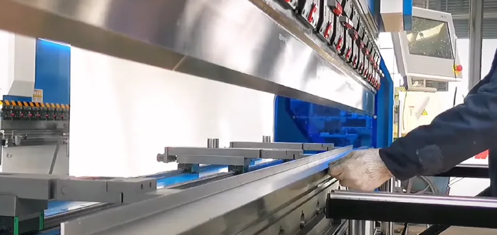
Bending is the workhorse of sheet metal working. A press brake—essentially a powerful mechanical or hydraulic press with specialized tooling—forces a flat sheet into angular shapes. Sounds simple? The technique behind it is surprisingly nuanced.
Two primary approaches dominate steel sheet bending operations: air bending and bottom bending. Understanding the difference helps you specify the right process for your tolerance requirements.
Air bending contacts the material at just three points: the punch tip and the two die shoulder radii. The bend angle depends on how far the punch descends into the die opening, not on the die's fixed angle. This flexibility means a single set of tooling can produce multiple bend angles—great for short runs and varied geometries. However, achieving consistently tight tolerances becomes more challenging because variations in material thickness, tensile strength, and grain direction all influence the final angle.
Bottom bending takes a different approach. The punch forces the material completely against the die angle, then applies additional pressure to overcome springback through a phenomenon called negative springback or springforward. Because the die angle dictates the final bend, bottom bending delivers superior control over tight tolerances. Defense and aerospace applications often require this method when precision is non-negotiable.
Which should you choose? For high-precision work with critical tolerances, bottom bending provides predictability. For shorter production runs with varying bend angles, air bending offers flexibility and quicker setup times. Metal bending services providers often maintain both capabilities to match technique to application.
Stamping: Progressive Dies and Compound Dies
When production volumes climb into the thousands, stamping becomes the go-to metal processing method. A die cut machine—whether a mechanical press or hydraulic system—forces sheet metal through hardened steel dies that shape, pierce, and form the material in rapid succession.
Progressive dies contain multiple stations arranged in sequence. With each press stroke, the material advances through stations that progressively complete the part—piercing holes at station one, forming flanges at station two, cutting the final profile at station three. Complex parts emerge fully formed at rates of hundreds per hour.
Compound dies perform multiple operations simultaneously in a single stroke. They're simpler than progressive dies but still achieve high efficiency for parts requiring several features formed at once.
Looking for metal stamping near me? Understanding these die types helps you communicate effectively with potential suppliers about your production requirements and expected volumes.
When Deep Drawing Outperforms Other Methods
Need a seamless cylindrical container, a battery housing, or a kitchen sink basin? Deep drawing excels where other techniques fall short. This process uses a punch to push flat sheet metal into a die cavity, creating parts with depth greater than their diameter.
The mechanics involve careful control of material flow. Hold-down pressure prevents wrinkling at the flange while the punch draws material into the cavity. For particularly deep parts, multiple drawing stages with intermediate annealing may be required to prevent tearing.
Deep drawing shines for:
- Seamless containers and enclosures (no welds to fail)
- Cylindrical and box-shaped housings
- Parts requiring uniform wall thickness
- Medium-to-high production volumes (500-5,000+ pieces)
Compared to welding multiple stamped pieces together, deep drawing produces stronger, more aesthetically consistent parts—often at lower per-unit costs once tooling is amortized.
Roll Forming, Stretch Forming, and Metal Spinning
Roll forming creates continuous profiles by passing sheet metal through a series of roller stations. Each station incrementally bends the material until the final cross-section emerges. Think of structural channels, rain gutters, and automotive trim—any component with consistent profile along its length.
Stretch forming clamps sheet metal edges while a die or form block stretches it into curved panels. Aircraft fuselage skins and architectural facades often rely on this technique for smooth, compound curves without wrinkling.
Metal spinning rotates sheet metal on a lathe-like machine while a forming tool progressively shapes it against a mandrel. This technique excels for axially symmetric parts—lighting reflectors, cookware, satellite dishes, and decorative domes. For quantities under 100 pieces, spinning often beats stamping on cost because tooling requirements are minimal.
Comparing Forming Techniques at a Glance
Selecting the right technique requires balancing geometry, volume, and budget. This comparison helps match your requirements to the optimal process:
| Technique | Part Geometry Suitability | Typical Thickness Range | Volume Sweet Spot | Relative Tooling Cost |
|---|---|---|---|---|
| Bending (Press Brake) | Angular bends, flanges, channels | 0.020" - 0.500" | 1 - 5,000 pieces | Low |
| Stamping (Progressive) | Complex flat parts with holes, forms | 0.010" - 0.250" | 10,000+ pieces | High |
| Deep Drawing | Cylindrical, box-shaped cavities | 0.015" - 0.125" | 500 - 50,000 pieces | Medium-High |
| Roll Forming | Continuous uniform profiles | 0.015" - 0.135" | 5,000+ linear feet | Medium |
| Stretch Forming | Large curved panels | 0.032" - 0.250" | 1 - 500 pieces | Low-Medium |
| Metal Spinning | Axially symmetric shapes | 0.020" - 0.250" | 1 - 1,000 pieces | Low |
Notice how volume dramatically influences technique selection. A part perfectly suited for spinning at 50 units might transition to deep drawing or stamping as quantities scale—and understanding these crossover points prevents costly process mismatches.
One additional consideration: kerf—the material lost during cutting—doesn't apply to forming operations themselves, but the blanks feeding your forming process still require cutting. Optimizing blank layouts minimizes waste before forming even begins.
With these core techniques understood, you're ready to explore how material selection directly impacts forming success—because even the perfect process choice fails if the material can't handle the required deformation.
Material Selection for Successful Forming Operations
You've chosen the right forming technique for your project. Now comes an equally critical decision: which material will actually cooperate with your forming process? The wrong choice leads to cracked bends, excessive springback, or parts that simply won't hold their shape. The right choice? Parts that form beautifully, meet specifications, and perform reliably in the field.
Each metal family behaves differently under forming forces. Understanding these behaviors helps you specify materials that work with your process rather than fighting against it.
Aluminum Alloys: Excellent Formability with Springback Challenges
Aluminum sheet metal ranks among the most formable materials available—lightweight, corrosion-resistant, and surprisingly cooperative during bending and drawing operations. The 3000 and 5000 series alloys offer excellent ductility for complex forms, while 6000 series aluminum sheets provide a balance of formability and strength after heat treatment.
Here's the catch: aluminum's lower elastic modulus means more elastic recovery after forming. Springback for aluminum typically ranges from 1.5° to 2° in tight bends—roughly double what you'd see with cold-rolled steel. Designers must account for this by specifying overbending or working closely with fabricators on compensation strategies.
For deep drawing applications, aluminum performs exceptionally well. Its high ductility allows material to flow smoothly into die cavities without tearing. Cookware, electronic enclosures, and automotive body panels frequently leverage aluminum's forming friendliness.
Stainless Steel: Work Hardening and Higher Forming Forces
Stainless steel sheet metal presents a different challenge entirely. While it offers superior corrosion resistance and aesthetic appeal, forming requires significantly more force and careful process control.
The key behavior to understand is work hardening. As you deform stainless steel, it gets progressively harder and more resistant to further forming. This property makes multi-stage forming operations particularly tricky—each stage increases the material's strength, requiring recalculation of forces for subsequent operations. Annealing between stages can restore ductility but adds time and cost.
Springback in stainless steel is substantial. According to forming specialists, 304 stainless steel exhibits 2° to 3° of springback in tight bends, and this can exceed 30° to 60° for large-radius bends in air forming operations. Half-hard 301 stainless can show even more dramatic recovery—up to 43° across certain radius ranges.
Compensation techniques become essential: overbending, bottoming instead of air bending, or using coining operations that apply extreme pressure to plastically thin the material at the bend line. Modern CNC press brakes with active angle control can measure and adjust in real time, helping achieve consistent results with this demanding material.
Carbon Steel: Predictable Performance Across Grades
For many forming applications, carbon steel remains the workhorse material. Its behavior is well-documented, predictable, and forgiving—exactly what you want when production deadlines loom.
Cold-rolled steel offers excellent surface finish and tighter thickness tolerances, making it ideal for visible components and precision applications. Springback typically falls between 0.75° and 1.0°—manageable with standard compensation techniques. Hot-rolled steel costs less and handles heavy-gauge forming well, though its mill scale surface requires finishing operations for many applications.
Various grades serve different purposes. Low-carbon steel (1008, 1010) forms easily with minimal cracking risk. Medium-carbon grades (1045, 1050) provide higher strength but require larger bend radii to prevent fracture.
Copper and Brass: High Ductility for Decorative Applications
When your application demands exceptional formability or decorative appeal, copper sheet metal and brass sheet become attractive options. These materials exhibit remarkably low springback—often less than 0.5°—making them ideal for precision decorative work and complex forms.
Copper's ductility allows aggressive forming operations that would crack other materials. Deep draws, tight bends, and intricate stamped patterns all become achievable. Electrical components, heat exchangers, and architectural elements frequently leverage copper's unique properties.
Brass combines copper's formability with improved strength and a distinctive golden appearance. Musical instruments, marine hardware, and decorative fixtures often specify brass for its forming characteristics and aesthetic qualities.
Understanding Grain Direction and Its Impact on Forming
Imagine wood grain—you can split wood easily along the grain but struggle against it. Metal sheets behave similarly, though less dramatically.
Rolling operations during sheet production align the metal's crystalline grain structure in the rolling direction. This creates directional properties that significantly affect forming behavior. Bending perpendicular to the grain direction (across the grain) generally produces better results: tighter minimum radii, reduced springback, and lower risk of edge cracking.
When bend lines must run parallel to the grain direction, increase your minimum bend radius by 25% to 50% as a safety margin. For critical applications, request material with grain direction marked so you can orient blanks optimally during nesting.
The difference matters most in tight-radius bends and high-strength materials. Stainless steel, in particular, shows pronounced grain direction sensitivity. Bending perpendicular to the grain direction can improve accuracy and reduce springback compared to parallel-grain bending.
Material Thickness Considerations for Different Forming Operations
Thickness fundamentally changes the rules of forming. What works beautifully in 0.030" stock may crack immediately in 0.125" material—even with identical alloy specifications.
The minimum bend radius rule provides essential guidance: for most materials, the inside bend radius should equal or exceed the material thickness. Aluminum often allows tighter radii (0.5T to 1T), while stainless steel may require 2T or more, especially in harder tempers. Thicker sheets require larger bend radii because bending induces greater tensile and compressive stresses that can cause cracking if the radius is too tight.
Thickness also affects forming force requirements. The relationship isn't linear—doubling thickness roughly quadruples the required bending force. This impacts equipment selection and tooling design, particularly for heavier gauges.
Die opening (V-opening) must scale with thickness. Thicker sheets require larger V-openings to prevent surface marring, allow proper material flow, and reduce strain on tooling. A general guideline suggests V-opening should equal 6 to 8 times material thickness for most applications.
Material-Specific Forming Considerations
When selecting materials for your custom sheet metal forming project, keep these practical guidelines in mind:
- Aluminum sheets: Allow 1.5° to 2° overbend compensation; consider annealed tempers (O or T4) for complex forms; avoid sharp radii in 7000 series alloys
- Stainless steel sheet metal: Expect 2° to 15°+ springback depending on radius; plan for 50% higher forming forces than carbon steel; consider annealing between multi-stage operations
- Carbon steel: Use minimum bend radius equal to material thickness; hot-rolled grades tolerate tighter radii than cold-rolled; watch for surface cracking at sharp bends in medium-carbon grades
- Copper sheet metal: Exceptional formability allows aggressive radii; soft temper copper can achieve radii as tight as 0.25T; work hardening increases strength during forming
- Brass sheet: Similar to copper but slightly less ductile; excellent for decorative stamping; half-hard temper provides good balance of formability and strength
Material selection directly determines whether your formed parts will succeed or fail. But even the perfect material choice can't compensate for poor design decisions. In the next section, we'll explore the design principles that ensure your parts are manufacturable from the start—covering critical DFM rules that prevent forming failures before they happen.
Design Principles That Make or Break Formed Parts
You've selected the perfect forming technique and chosen an ideal material. Now comes the moment of truth: will your design actually survive the forming process? Too many projects derail at this stage—not from material failures or equipment limitations, but from preventable design oversights.
Design for Manufacturability (DFM) transforms theoretical part concepts into producible reality. When you're creating custom metal parts through forming operations, specific geometric rules govern what's achievable versus what's destined for the scrap bin. Understanding these rules before submitting designs saves costly iterations and keeps your sheet metal prototype moving toward production.
Critical DFM Rules That Prevent Forming Failures
Think of sheet metal like thick cardboard. Fold it too sharply, and the outer surface cracks. Position holes too close to bends, and they distort into unusable ovals. Every DFM rule exists because engineers learned these lessons the expensive way.
Minimum Bend Radius: The inside curve of your bend should at least match the material thickness. Designing all bends to the same radius allows fabricators to use a single tool for every fold, reducing setup time and lowering your costs. For harder materials like stainless steel or hardened aluminum, increase this to 2T or greater.
Hole-to-Bend Spacing: Position holes at least 2.5 times the material thickness plus one bend radius away from any bend line. Holes placed too close will stretch and distort during forming, making it impossible to pass fasteners through or maintain assembly alignment. A 0.060" thick part with a 0.060" bend radius needs holes positioned at least 0.210" from the bend.
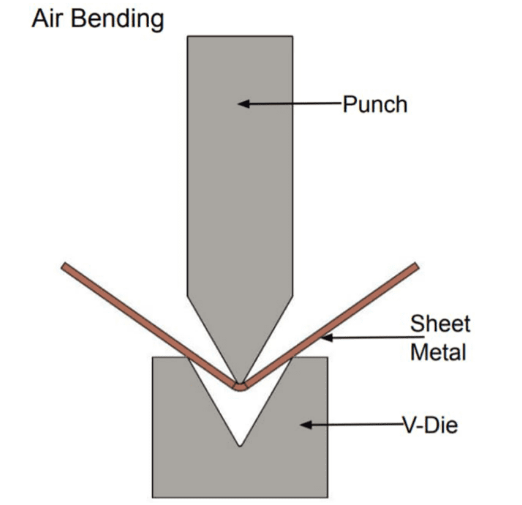
Bend Relief Requirements: When a bend terminates at an edge rather than continuing across the full sheet width, material wants to tear at that junction. Adding small rectangular or circular cutouts (bend reliefs) at bend terminations prevents cracking and ensures clean, professional edges. Relief width should equal or exceed the material thickness, with length extending past the bend line.
Minimum Flange Length: Press brake tooling needs adequate surface area to grip and control the material during bending. Flanges shorter than four times the material thickness create "illegal" features that require expensive custom tooling—potentially doubling production costs. A 0.050" thick sheet needs flanges at least 0.200" long.
Grain Direction Alignment: Metal sheets have internal grain structure from the rolling process. Designing bends perpendicular to the grain direction prevents cracking that might not appear until months after delivery. This "hidden" rule becomes critical for parts subjected to vibration or repeated stress.
Narrow Feature Limits: Laser and punch cutting generate heat that can warp thin fingers or narrow slots. Keep narrow cutouts at least 1.5 times wider than the material thickness to maintain flatness and ensure parts fit into assemblies without forcing.
Designing for Springback Compensation
Here's a frustrating reality of precision sheet metal fabrication: bend the material to exactly 90°, release the tooling, and watch it spring back to 88° or 89°. Every formed part exhibits this elastic recovery, and ignoring it guarantees out-of-spec components.
Springback occurs because the inner bend surface compresses while the outer surface stretches. These opposing forces create residual stresses that partially release when forming pressure disappears. The magnitude varies by material—aluminum springs back more than steel, stainless more than both.
Compensation strategies fall into three categories:
- Overbending: Form the part past the target angle so springback brings it to specification. A 90° target might require forming to 92° or 93° depending on material
- Bottom bending or coining: Apply additional pressure at the bend apex to plastically deform the material beyond its elastic limit, reducing recovery
- Material selection: Specify materials with lower springback characteristics when tight angle tolerances are critical
Modern CNC press brakes with angle measurement systems can automatically compensate for springback, measuring the actual bend and adjusting in real time. When working with a precision sheet metal fabricator, discuss their compensation capabilities during sheet metal engineering reviews.
Tolerance Expectations: Formed parts simply cannot achieve machined-part precision. Being too strict on tolerances where it isn't functionally necessary increases inspection time and cost. Standard sheet metal tolerances of ±1° on bend angles and ±0.010" to ±0.030" on formed dimensions keep projects on budget while meeting most functional requirements. Reserve tighter tolerances for features that genuinely require them.
DFM Checklist for Sheet Metal Prototyping
Before submitting designs for sheet metal prototyping or production quotes, verify these critical considerations:
- Bend radii equal or exceed material thickness (2T minimum for stainless steel and hardened aluminum)
- Holes positioned at least 2.5T plus bend radius from all bend lines
- Bend reliefs included where bends terminate at edges
- Flange lengths meet 4T minimum requirement
- Grain direction considered and documented for critical bends
- Narrow slots and fingers exceed 1.5T width
- Tolerances appropriate for forming process capabilities
- Springback compensation discussed with fabricator for critical angles
- Standard hole sizes specified to enable high-speed punching
Following these guidelines doesn't just prevent forming failures—it positions your project for competitive pricing and faster turnaround. Fabricators recognize well-designed parts immediately, and that recognition translates into smoother production and stronger supplier relationships.
With DFM principles mastered, you're ready to evaluate when forming makes economic sense compared to alternative fabrication methods. The next section explores those cost crossover points and helps you determine the optimal approach for your specific volumes and geometries.
Choosing Between Forming and Alternative Fabrication Methods
So you've designed a part that could theoretically be produced several different ways. Should you form it from sheet metal, machine it from solid stock, cut and weld flat pieces together, or explore casting options? The answer depends on your specific combination of geometry, volume, budget, and timeline. Making the wrong call here can double your costs or add weeks to delivery.
Let's cut through the confusion and examine when custom sheet metal forming genuinely outperforms alternatives—and when other methods might serve you better.
Forming vs. Machining for Your Application
This comparison comes up constantly, and for good reason. Both processes produce precision metal parts, but they approach the problem from opposite directions.
Metal cutting through CNC machining starts with solid stock and removes material until your part emerges. Every chip that falls represents purchased material going to waste—sometimes 80% or more of the original block. The process excels at complex three-dimensional geometries, tight tolerances, and intricate internal features that forming simply cannot achieve.
Custom sheet metal forming reshapes existing material without removing any of it. Material waste stays minimal—typically just the skeleton remaining after blank cutting. The tradeoff? Your geometry must originate from a flat sheet, limiting what's geometrically possible.
Here's the practical breakdown:
- Thin-walled enclosures and housings: Forming wins decisively. Sheet metal fabrication creates lightweight structures using thin material (typically 0.040" to 0.125" thick), while machining thin walls from solid blocks wastes enormous amounts of material and machine time.
- Complex internal pockets and undercuts: Machining handles almost any geometry a designer can create. Forming cannot produce these features.
- Parts with multiple bends and flanges: Forming produces these efficiently in minutes. Machining equivalent features requires hours of tool paths and material removal.
- Prototype quantities (1-10 units): Machining often costs less because no tooling investment is required. Programming changes are quick and inexpensive.
Searching for metal cutting near me? Consider whether your parts actually require machining's capabilities, or whether forming could deliver equivalent function at lower cost.
Volume Thresholds Where Forming Becomes Cost-Effective
The economics shift dramatically as quantities increase. Understanding these crossover points prevents costly process mismatches.
For prototype quantities of 1-10 units, CNC machining costs may be competitive because forming requires tooling setup that can't be amortized across many parts. But here's where it gets interesting: at volumes above 50 units, sheet metal fabrication almost always costs less per part.
Why the dramatic shift? Several factors converge:
- Tooling amortization: Press brake dies and forming punches spread their cost across more units, dropping per-piece tooling contribution rapidly
- Cycle time advantages: Forming operations complete in seconds to minutes. Complex machined geometries might require hours of machine time per part.
- Material efficiency: Sheet stock costs less than equivalent solid blocks, and forming preserves nearly all purchased material
- Nesting optimization: Multiple blanks can be cut from single sheets, reducing material cost per part as quantities grow
How much to get a metal part made? At 100 units, formed parts typically cost 30-50% less than machined equivalents for appropriate geometries. At 1,000 units, that gap often widens to 60-80% savings.
Laser Cutting with Welded Assemblies: A Middle Ground
Sometimes the answer isn't pure forming or pure machining—it's a hybrid approach. Laser cutting flat profiles and welding them into three-dimensional assemblies offers flexibility that neither process provides alone.
This approach shines for:
- Custom metal shapes with varying wall thicknesses in different sections
- Parts requiring material transitions (different alloys in different areas)
- Low-volume production where forming tooling can't be justified
- Geometries that would require multiple forming operations to achieve
The downsides? Weld joints create potential failure points, assembly labor adds cost, and surface finishing becomes more complex around weld areas. For structural applications where joint integrity matters, formed single-piece construction often proves superior.
Casting and 3D Printing: When They Make Sense
Casting becomes attractive for complex three-dimensional parts at high volumes—typically 5,000+ units. The process excels at organic shapes impossible to form from sheet metal. However, tooling costs run substantially higher than forming dies, and lead times for first articles extend to weeks or months. Some projects transition to cast parts with CNC finish machining for volume production, combining casting's material efficiency with machining's precision for critical features.
Metal 3D printing eliminates tooling entirely but carries high per-part costs and limited material options. It's ideal for complex geometries at very low volumes (1-20 units) or for parts impossible to produce any other way. For most production applications, forming remains far more economical.
Comparing Fabrication Methods Across Key Criteria
This comparison helps match your specific requirements to the optimal process:
| Fabrication Method | Unit Cost (Low Vol.) | Unit Cost (Med. Vol.) | Unit Cost (High Vol.) | First Article Lead Time | Geometric Complexity | Material Waste |
|---|---|---|---|---|---|---|
| Sheet Metal Forming | Medium-High | Low | Very Low | 1-2 weeks | Limited to sheet-based geometries | 5-15% |
| CNC Machining | Medium | High | Very High | 3-5 days | Excellent—nearly unlimited | 50-90% |
| Laser Cut + Weld | Low-Medium | Medium | Medium-High | 1-2 weeks | Good—assembly flexibility | 15-25% |
| Casting | Very High | Medium | Low | 6-12 weeks | Excellent—organic shapes possible | 10-20% |
| Metal 3D Printing | Very High | Very High | Prohibitive | 1-2 weeks | Exceptional—almost no limits | 5-10% |
Notice how forming's cost advantage grows with volume while machining becomes increasingly expensive. Sheet metal fabrication scales smoothly from prototype through production—the same process that produces 10 units works for 1,000 with minor setup changes. Meanwhile, machining often requires complete process redesign when scaling beyond prototypes.
Part Geometry Factors That Favor Forming
Certain design characteristics signal that forming will outperform alternatives:
- Thin walls: Material thicknesses under 0.250" form efficiently while machining thin sections wastes material and risks chatter
- Complex bend sequences: Multiple flanges, returns, and angles that would require extensive machining form in minutes
- High strength-to-weight requirements: Forming preserves material grain structure, often yielding stronger parts than machined equivalents
- Large surface areas: Panels and enclosures form from standard sheet sizes economically
- Symmetrical profiles: Roll forming and metal spinning excel at continuous or axially symmetric shapes
When these characteristics align with your design, forming typically delivers the best combination of cost, lead time, and performance. But achieving that optimal outcome requires understanding what happens after forming—the secondary operations and finishing processes that transform formed blanks into finished components.
Secondary Operations and Finishing for Formed Parts
Your formed part emerges from the press brake looking almost ready—but "almost" doesn't ship to customers. Raw formed edges are sharp enough to cut skin. Surfaces need protection from corrosion. Threaded fasteners require permanent mounting points. These secondary operations transform rough formed blanks into finished, functional components ready for assembly.
Understanding the sequence and options for these operations helps you specify requirements correctly and avoid costly rework. Let's walk through the essential processes that complete your custom sheet metal forming project.
Deburring: Removing Sharp Edges Safely
Every cutting and forming operation leaves burrs—those tiny raised edges and protrusions that create safety hazards and assembly problems. Without consistent deburring, burrs can cause longevity, safety, and functionality issues ranging from cut fingers during assembly to interference with mating parts.
Three primary deburring approaches serve different production needs:
- Manual deburring: Operators use handheld tools—files, scrapers, or abrasive pads—to remove burrs from individual parts. This economical method works well for low volumes but becomes time-consuming at scale. Brushing methods use rotating discs with metal or wire filaments to scrape off burrs quickly, while sanding employs abrasive materials like aluminum oxide to smooth raised surfaces.
- Tumbling (mechanical deburring): Parts rotate in drums or vibratory bowls with abrasive media that uniformly removes burrs across all surfaces. Mechanical deburring offers efficiency, reliability, and speed—ideal for medium-to-high volumes where consistent results matter more than individual part attention.
- Electrochemical deburring: This method uses electrolysis to dissolve burrs through anodic metal dissolution, targeting only the areas where burrs exist. The process handles challenging metals with high accuracy but requires careful management of chemical compounds.
For formed sheet metal, mechanical tumbling typically provides the best balance of cost and quality—especially when parts will receive subsequent surface finishing that benefits from uniformly prepared edges.
Surface Finishing Options for Formed Sheet Metal
Bare metal rarely stays bare for long. Corrosion protection, aesthetic requirements, and functional properties drive finish selection. Each option interacts differently with formed parts, and timing matters critically.
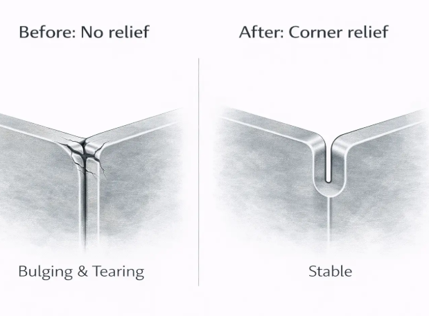
Powder coating electrostatically applies dry powder particles that cure into a durable, uniform finish under heat. Powder coating services deliver excellent corrosion resistance and color options. However, powder coating thickness prevents full installation of self-clinching fasteners—the fastener "clinches" into the coating rather than the metal itself. Install hardware before powder coating, or mask mounting areas.
Anodizing creates a protective oxide layer on aluminum through an electrochemical process. Anodized aluminum resists corrosion, accepts dyes for color, and provides excellent wear resistance. Standard anodizing generally works well with aluminum fasteners, though hard-coat anodizing increases surface hardness and decreases ductility—potentially interfering with self-clinching operations if performed before fastener installation.
Electroplating (zinc, nickel, chrome) deposits thin metal layers for corrosion protection and appearance. Plating an assembly with fasteners already installed requires careful attention: excessive plating buildup in threads causes "tight" or non-gageable threads, and trapped plating solutions can corrode the fastener-to-panel connection over time.
Brushing and grinding create consistent surface textures—from fine satin finishes to coarse industrial patterns. These mechanical finishes hide minor surface imperfections while providing distinct visual appeal for architectural and consumer applications.
Hardware Integration During and After Forming
Formed parts frequently require permanent mounting points for threaded fasteners. Three primary hardware families serve this need, each with distinct installation timing requirements.
PEM self-clinching fasteners (nuts, studs, standoffs) press permanently into sheet metal during fabrication. Upon installation, they become integral parts of the assembly and will not loosen or fall out even when mating hardware is removed. Self-clinching works best when installed before most surface finishing operations—though thick coatings like powder coat require masking the installation areas.
Weld nuts attach through projection welding or capacitive discharge welding, forming powerful bonds suitable for applications where only one side of the material is accessible. Various types serve specific needs: hex projection weld nuts handle high-torque applications, while round base weld nuts work with automated feeding equipment in restricted spaces. Welded hardware typically receives surface finishing after installation.
Rivets mechanically fasten through hole expansion, creating permanent joints without heat or electrical current. Blind rivets install from one side only—valuable when back access is impossible. Solid rivets require access to both sides but provide maximum shear strength. Riveting typically occurs after surface finishing to preserve coating integrity around rivet heads.
Sequencing Secondary Operations Correctly
The order of operations significantly impacts final quality. While finishing a panel before installing self-clinching fasteners is always preferred, production realities sometimes require finishing assemblies with hardware already installed. Understanding the risks helps you plan accordingly.
Here's the typical production sequence for formed sheet metal parts:
- Forming operations: All bending, stamping, and drawing completed first
- Deburring: Remove sharp edges immediately after forming
- Self-clinching hardware insertion: Install PEM fasteners before coating operations
- Surface preparation: Cleaning, chemical pretreatment for coating adhesion
- Surface finishing: Powder coat, anodize, plate, or paint
- Thread masking removal: If threads were protected during finishing
- Welding operations: Spot welding or projection welding of additional hardware
- Final assembly: Riveting, adhesive bonding, mechanical fastening
- Inspection and packaging: Verify dimensions, finish quality, hardware function
Deviating from this sequence creates complications. Forming after finishing damages coatings at bend lines. Installing self-clinching fasteners after thick coatings prevents proper metal-to-metal clinching. Welding after powder coating burns through the finish and releases toxic fumes.
When your project progresses from secondary operations to production scaling, the next challenge emerges: how do you validate designs before committing to expensive production tooling? That transition from prototype to mass production requires different strategies at each stage—strategies we'll explore in the following section.
From Prototype to Production Scale
You've validated your design on paper. DFM principles check out. Material selection makes sense. Now comes a critical question: how do you physically prove your concept works before investing thousands in hardened steel production tooling? The answer lies in understanding the distinct tooling and process strategies that bridge early-stage validation to full-scale sheet metal manufacturing.
Prototype sheet metal parts serve a fundamentally different purpose than production runs. They exist to catch design flaws, verify fit and function, and validate forming feasibility—all before you commit to expensive permanent tooling. Getting this transition right separates projects that launch on schedule from those that spiral into costly redesign cycles.
Rapid Prototyping Strategies for Formed Parts
Traditional thinking assumed prototype forming required the same hardened steel dies used in production. That assumption added weeks of lead time and thousands in tooling costs just to validate a concept. Modern rapid sheet metal approaches have changed the equation dramatically.
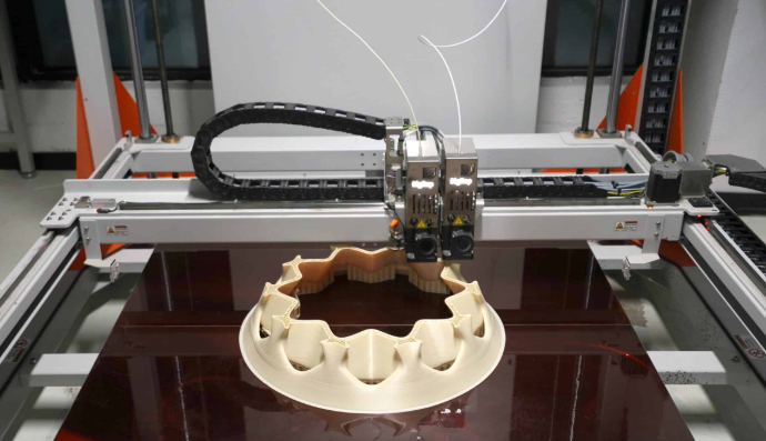
3D-printed forming tools represent one of the most significant shifts in prototyping strategy. What once took weeks to produce—heavy, expensive rigid metal forms—are now being replaced by speedy and light carbon fiber filled 3D printed tooling. Companies like East/West Industries, a tier-one aerospace supplier, report 87% time savings and 80% cost savings by switching to in-house 3D printed dies for prototype and low-volume forming.
How does plastic tooling form metal? High-performance polymers like carbon fiber filled nylon and polycarbonate possess the stiffness required to shape sheet metal under hydraulic press forces. 3D printed tools significantly outperform metal ones for hard tool design validation to bridge the prototype to production phase and for low-run production. The approach works particularly well for:
- Design validation before committing to permanent tooling
- Low-volume production runs (typically under 100 pieces)
- Iterative design cycles where geometry may change between batches
- Parts with moderate forming forces (thinner gauges, softer materials)
Urethane dies offer another soft tooling option. These rubber-like forming tools conform around sheet metal during pressing, creating shapes without the precision of hardened steel but at a fraction of the cost and lead time. Urethane tooling excels for shallow draws and simple bends where exact dimensional control matters less than proof-of-concept validation.
Manual brake forming requires no dedicated tooling at all for basic bend prototypes. Skilled operators use universal press brake tooling—standard V-dies and punches—to create bent prototypes directly from flat blanks. This approach delivers prototype sheet metal parts within days rather than weeks, though complex multi-bend geometries become increasingly challenging to execute accurately.
The beauty of these approaches? The cycle between design time and use is short and cost effective, making it easier for companies to act quickly and to make design iterations along the way if necessary.
Scaling from Prototype to Mass Production
Once prototypes validate your design, the path to volume production requires fundamentally different tooling investments. Understanding what changes—and what stays constant—helps you plan realistic timelines and budgets.
Production tooling differences: Where prototype forming might use 3D-printed dies that produce dozens of parts before wearing, production tooling employs hardened steel dies designed for hundreds of thousands of cycles. Progressive dies—containing multiple forming stations in sequence—become economical at volumes exceeding 10,000 pieces, automating what would otherwise require multiple manual operations.
Custom sheet metal fab operations at production scale look dramatically different from prototype work. Automated feeding systems replace manual blank loading. In-die sensors monitor forming forces and detect anomalies. Statistical process control ensures every thousandth part matches the first. These capabilities require upfront investment but deliver consistency impossible to achieve manually.
Lead time expectations vary significantly by volume:
- Prototype quantities (1-25 pieces): 3-10 business days using soft tooling or manual forming
- Low volume (25-500 pieces): 2-4 weeks, potentially using soft tooling for simpler geometries
- Medium volume (500-5,000 pieces): 4-8 weeks including hardened tooling fabrication
- High volume (5,000+ pieces): 8-16 weeks for progressive die development and production ramp
Sheet metal shops serving production volumes maintain fundamentally different capabilities than prototype-focused operations. Production facilities invest in automated press lines, robotic material handling, and quality systems certified to industry standards. Prototype shops prioritize flexibility and speed over throughput capacity.
The Prototype-to-Production Progression
Planning your project timeline requires understanding the typical stages between concept and volume production. Each stage serves specific validation purposes:
- Concept prototypes: First physical parts using soft tooling or manual forming—validates basic geometry and identifies obvious design issues
- Functional prototypes: Parts meeting dimensional specifications for fit and assembly testing—often still using soft tooling but with tighter process control
- Pre-production samples: Parts produced using production-intent tooling—validates that final tooling produces conforming parts
- Pilot production: Small batch (50-200 pieces) using production tooling at production speeds—identifies process issues before full ramp
- Production ramp: Gradual increase to target volumes with ongoing quality monitoring
Before mass production, the prototype serves as a check. If it meets all requirements, the design can move forward. If it fails, changes are still inexpensive at this stage compared to discovering faults after production has begun.
For engineers validating designs, this progression provides multiple checkpoints to catch issues early. For procurement professionals, understanding these stages enables realistic timeline planning and helps avoid the common trap of expecting production-quality parts on prototype schedules.
The transition from validated prototype to production partner selection represents the final critical decision point. Choosing the right custom forming partner—one with appropriate equipment, certifications, and engineering support—determines whether your carefully developed design translates into consistent, high-quality production parts.
Selecting the Right Custom Forming Partner
Your design is validated. Prototypes perform as expected. Now comes a decision that shapes everything downstream: which manufacturing partner will transform your validated concept into consistent production reality? Searching for sheet metal fabrication shops near me or metal fabrication companies near me yields countless options—but not all custom metal fabricators deliver equal value.
The right partner does far more than press parts. They catch design issues before tooling commits, communicate proactively when challenges arise, and deliver quality that keeps your production lines running. The wrong choice? Missed deadlines, out-of-spec parts, and endless firefighting that drains engineering resources.
What to Look for in a Forming Partner
Evaluating potential suppliers requires looking beyond quoted prices to capabilities that determine long-term success. If your supplier doesn't have the same priorities as you, it could be time to take a step back and re-evaluate your options. Focus on these critical criteria:
Equipment capabilities: Does the facility maintain the press brake tonnage, die capacity, and automation level your volumes require? Production-scale projects need different equipment than prototype work. Verify that their machinery matches your material thicknesses, part dimensions, and annual quantity projections.
Quality certifications: Certifications reveal systematic quality commitments. ISO 9001 establishes baseline quality management. For automotive applications, IATF 16949 certification becomes essential—it is the standard for Automotive Quality Management Solutions (QMS) that ensures defect prevention, variation reduction, and continual improvement. Partners like Shaoyi (Ningbo) Metal Technology maintain IATF 16949 certification specifically for chassis, suspension, and structural components—demonstrating the systematic approach automotive OEMs and tier-one suppliers require.
Engineering support availability: Can their engineers review your designs and identify manufacturability issues before quoting? It's important to clarify whether the client will provide detailed design specifications or if the fabricator is expected to handle the design work in-house. Comprehensive DFM support—like Shaoyi's approach that pairs 5-day rapid prototyping with manufacturing expertise—catches problems when changes cost nothing rather than after tooling is cut.
Communication responsiveness: When you call or email your supplier, how long does it take for them to get back to you? Rapid quote turnaround—some capable partners deliver quotes within 12 hours—signals operational efficiency that typically extends to production performance. Communication should flow both ways; quality suppliers proactively update you rather than waiting for you to chase status.
Maximizing Value Through Supplier Collaboration
Finding a qualified supplier is just the starting point. Building a collaborative relationship unlocks value that transactional purchasing never captures.
The real key is to look for suppliers that hit the dates they commit to. This sometimes means accepting pushback on aggressive timelines. Having that openness and trust forms the foundation of partnerships where suppliers invest in your success rather than simply processing orders.
Budget is a sensitive topic, but it's essential to discuss it early on. Knowing your target cost allows suppliers to suggest material substitutions, design modifications, or process changes that deliver required function at achievable prices. The number at the bottom of a quote tells only part of the story—value emerges from total cost of ownership including quality, delivery reliability, and engineering support.
A true partnership requires both trust and the ability to take risks. Does your sheet metal supplier embrace challenges or shy away from unfamiliar requirements? Growing your business means incorporating new materials or technologies—partners willing to develop solutions alongside you become competitive advantages rather than mere vendors.
Questions to Ask Potential Suppliers
Before committing to a forming partner, gather information that reveals true capabilities and cultural fit:
- What quality certifications do you maintain, and when were they last audited?
- Can you provide DFM feedback before I finalize my design?
- What is your typical quote turnaround time for new projects?
- How do you handle design changes after tooling has been produced?
- What is your on-time delivery performance over the past 12 months?
- Do you own delivery vehicles, or do you rely on third-party freight?
- What happens when quality issues arise—how do you resolve and prevent recurrence?
- Can you scale from prototype through production volumes using the same processes?
- What material certifications and traceability documentation do you provide?
- How confident are you that I will receive my parts when you say I will?
Accountability is the foundation of trust and trust underpins every strong supplier/customer relationship. When things don't go as planned—and eventually something will—partners who take responsibility and implement corrective actions prove far more valuable than those who deflect blame.
The journey from first bend to final part requires more than technical knowledge—it demands partnership with manufacturers who share your commitment to quality and delivery. Whether you're sourcing metal fabrication near me for local convenience or evaluating global suppliers for cost optimization, the evaluation criteria remain constant: capability, certification, communication, and collaboration. Apply these principles, ask the right questions, and you'll find partners who transform your custom sheet metal forming projects from concepts into competitive advantages.
Frequently Asked Questions About Custom Sheet Metal Forming
1. What is the difference between sheet metal forming and fabrication?
Sheet metal forming specifically reshapes flat metal into three-dimensional parts without removing material—think bending, stamping, and deep drawing. Metal fabrication is a broader term encompassing cutting, welding, forming, and assembly operations. Forming preserves the metal's grain structure, often creating stronger parts than machined equivalents. This distinction matters when specifying parts because forming operations maintain material integrity while achieving complex geometries efficiently.
2. How much does custom sheet metal fabrication cost?
Custom sheet metal forming costs depend on volume, complexity, and tooling requirements. For prototype quantities (1-25 pieces), expect higher per-unit costs due to setup time. At 50+ units, forming typically costs 30-50% less than machined alternatives. Production volumes of 1,000+ pieces can achieve 60-80% savings. Tooling investment ranges from minimal for manual brake forming to significant for progressive dies, but amortizes quickly at higher volumes. Partners offering 12-hour quote turnaround, like IATF 16949-certified manufacturers, help you evaluate costs accurately before committing.
3. What materials work best for sheet metal forming?
Material selection significantly impacts forming success. Aluminum offers excellent formability but requires 1.5-2° overbend compensation for springback. Carbon steel provides predictable behavior with manageable 0.75-1.0° springback. Stainless steel demands higher forming forces and exhibits 2-15°+ springback depending on bend radius. Copper and brass deliver exceptional ductility with minimal springback under 0.5°—ideal for decorative applications. Always consider grain direction: bending perpendicular to grain reduces cracking risk and improves dimensional accuracy.
4. What certifications should a sheet metal fabrication company have?
Quality certifications reveal systematic manufacturing commitments. ISO 9001 establishes baseline quality management for general applications. For automotive components—chassis, suspension, structural parts—IATF 16949 certification is essential as it's the automotive industry standard for quality management systems ensuring defect prevention and continuous improvement. Aerospace applications may require AS9100. When evaluating suppliers, verify certification dates and ask about recent audits to confirm ongoing compliance rather than lapsed credentials.
5. How long does custom sheet metal prototyping take?
Prototype lead times vary by complexity and tooling approach. Using 3D-printed forming tools or manual brake forming, simple prototypes can ship in 3-10 business days. Low-volume runs (25-500 pieces) typically require 2-4 weeks. Production tooling development extends timelines to 4-16 weeks depending on die complexity. Rapid prototyping services offering 5-day turnaround with comprehensive DFM support help validate designs quickly before committing to expensive hardened production tooling.