 Small batches, high standards. Our rapid prototyping service makes validation faster and easier —

Custom Metal Forming Decoded: Match Your Project To The Right Process
Understanding Custom Metal Forming and Why It Matters
When you're sourcing metal components for your next project, you've probably encountered the terms "metal forming" and "metal fabrication" used interchangeably. Here's the problem: they're not the same thing. Confusing these processes can lead to costly mistakes, production delays, and parts that don't meet your specifications.
Custom metal forming refers specifically to the process of reshaping metal into desired geometries using force and deformation—without removing any material. Think of it like sculpting clay rather than carving wood. The metal is bent, stretched, compressed, or drawn into shape while maintaining its original mass. This fundamental characteristic makes it distinctly different from general metal processing methods.
What Sets Metal Forming Apart from Fabrication
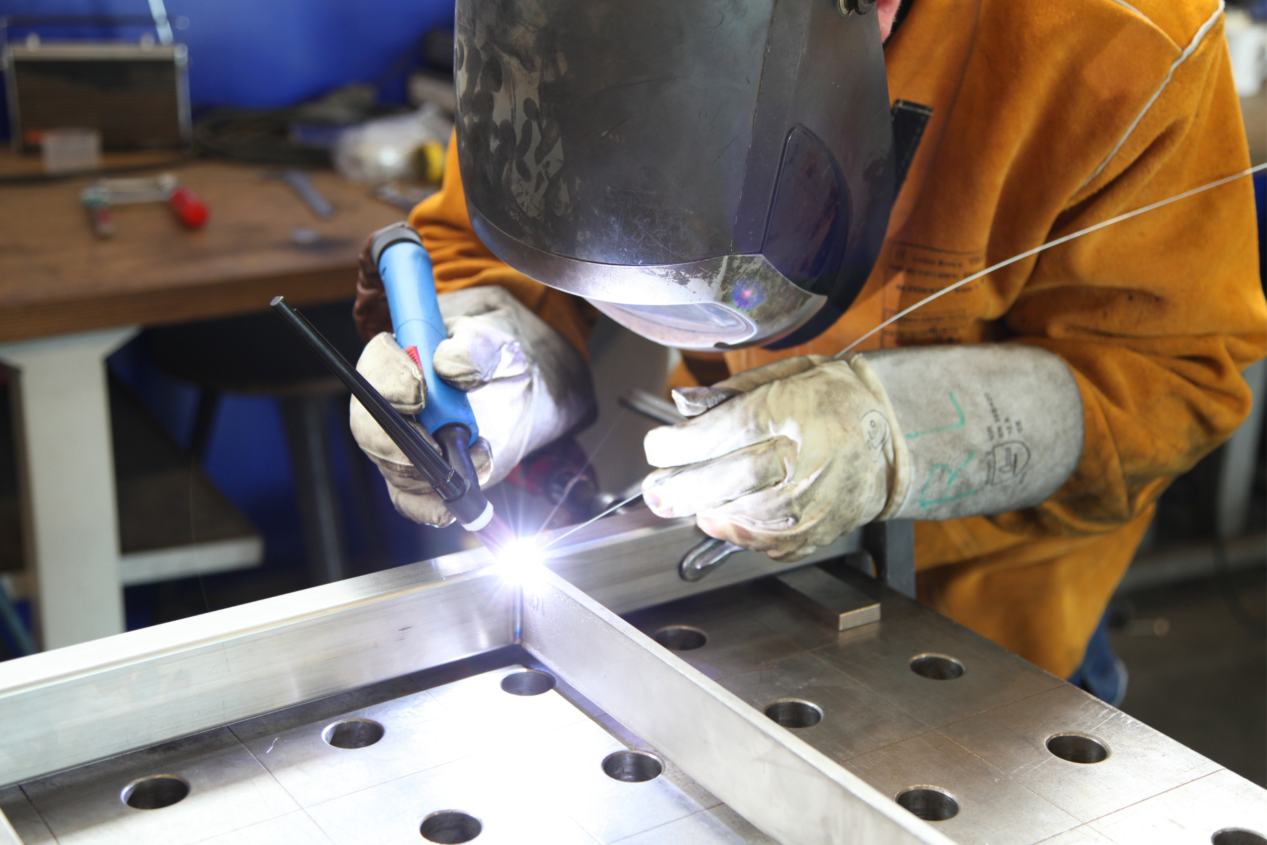
So what is metal fabrication, exactly? Metal fabrication is a broader category that encompasses multiple metalworking techniques, including cutting, welding, drilling, and machining. These processes often involve material removal or joining separate pieces together. A metal fab shop might cut steel plates, weld them into frames, and drill mounting holes—all fabrication activities.
Custom metal forming, on the other hand, focuses exclusively on reshaping operations. When you bend a steel bracket, stamp an automotive panel, or roll a cylindrical tube, you're forming metal. The material transforms geometrically without losing substance.
Metal forming reshapes material through controlled deformation, while fabrication typically involves cutting, joining, or material removal. Understanding this distinction is essential for selecting the right manufacturing approach.
Why does this matter for engineers and procurement specialists? The distinction directly impacts your project's cost structure, lead times, material efficiency, and part performance. Forming processes often produce stronger components because the metal's grain structure flows with the shape rather than being interrupted by cuts or welds. Steel forming operations, for instance, can create structural components with superior fatigue resistance compared to welded assemblies.
The Core Principle Behind Reshaping Metal
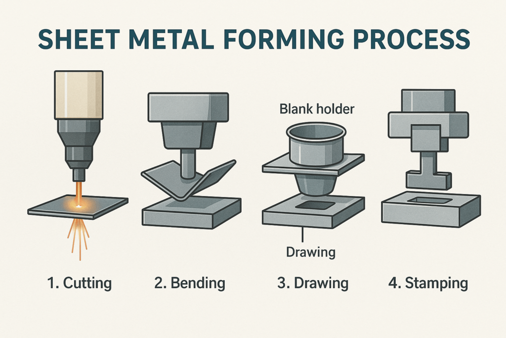
At its core, metal forming exploits the plastic deformation properties of metals. When force exceeds a metal's yield strength, it permanently changes shape without fracturing. This principle enables several key forming techniques:
- Bending – Deforming metal around a linear axis to create angles and curves
- Stamping – Using dies to press sheet metal into specific shapes
- Rolling – Passing metal through rollers to reduce thickness or create profiles
- Deep Drawing – Stretching sheet metal into hollow, cylindrical, or box-shaped parts
Each technique applies controlled forces that reshape the workpiece while preserving—and often enhancing—material properties. Unlike machining, where chips are cut away, forming retains 100% of your raw material in the finished part.
For manufacturers focused on efficiency, this means minimal waste and maximum material utilization. For engineers, it translates to components with continuous grain flow and consistent mechanical properties throughout the part geometry.
Understanding these fundamentals positions you to make smarter decisions when specifying parts, evaluating suppliers, or optimizing designs for production. The following sections will break down each forming process, helping you match your project requirements to the right technique.
Primary Metal Forming Processes Explained
Now that you understand what separates forming from fabrication, let's dive into the specific processes that shape raw metal into functional components. Each technique offers distinct advantages depending on your part geometry, production volume, and material requirements. Knowing these differences helps you communicate effectively with suppliers and make informed decisions about your manufacturing approach.
Bending and Press Brake Operations Explained
Bending is one of the most common custom metal bending operations you'll encounter. At its simplest, bending deforms sheet or plate metal along a straight axis to create angles, channels, and curved profiles. The workhorse of this process? The press brake—a machine that uses a punch and die to force metal into precise angles.
But not all bending techniques work the same way. Understanding the differences helps you specify the right approach for your tolerances and budget:
- Air Bending – The punch presses the metal into a V-shaped die, but leaves an air gap between the sheet and the die bottom. This method requires less force and allows flexibility in achieving different angles with the same tooling. However, it produces slight springback, where the metal partially returns toward its original shape after forming.
- Bottom Bending (Bottoming) – Here, the sheet metal "bottoms out" against the die, creating full contact. This produces more precise bends with minimal variation between parts—ideal when accuracy matters more than speed.
- Coining – Uses higher forces to completely deform thinner materials into complex shapes with the highest degree of precision. The intense pressure virtually eliminates springback.
Which method delivers better results? That depends on your priorities. If you need consistent, precise bends with minimal part-to-part variation, bottom bending is your best bet. If you're more concerned about surface appearance and production speed, air bending might be preferable since it involves less forceful contact and reduces the risk of tooling marks.
Steel sheet bending projects often balance these tradeoffs based on volume and tolerance requirements. Metal bending services providers typically recommend air bending for lower volumes and simpler geometries, reserving bottoming for tighter specifications.
Stamping, Rolling, and Advanced Forming Techniques
Beyond bending, several other forming processes address more complex geometries and higher production demands. Here's what you need to know about each:
Stamping uses dies mounted in presses to cut, punch, and form sheet metal into specific shapes. The type of die setup you choose dramatically affects your costs and capabilities:
- Progressive Dies – Designed for high-volume production of complex parts. The workpiece moves through sequential stations, each performing a specific operation. According to industry experts, these dies have higher upfront tooling costs but significantly lower per-part costs at scale.
- Transfer Dies – Move workpieces independently between stations using mechanical transfer systems. Best for larger or intricate parts requiring multiple operations.
- Compound Dies – Perform multiple operations like cutting and punching in a single stroke. Less expensive to produce but better suited for simpler, flat parts.
Rolling passes metal through sets of rollers to achieve different outcomes:
- Plate Rolling – Curves flat plates into cylindrical or conical shapes for tanks, pressure vessels, and structural components. This plate forming technique handles thicker materials that other processes can't easily shape.
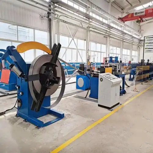
- Roll Forming – Continuously feeds strip metal through consecutive roller stations to create long profiles with consistent cross-sections. Roll forming services are ideal for producing channels, angles, and custom profiles at high volumes.
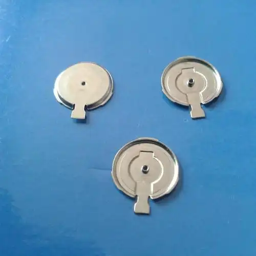
Deep Drawing stretches sheet metal into hollow, three-dimensional shapes using a punch that forces the blank into a die cavity. This cold-forming process creates seamless cylindrical parts, boxes, and complex enclosures without welding. It's particularly effective for symmetrical, uniform shapes requiring structural integrity.
Hydroforming takes deep drawing further by using pressurized fluid—typically up to 10,000 PSI—to force sheet metal over a die. According to Toledo Metal Spinning, this specialized process allows asymmetrical or irregular geometries that conventional deep drawing can't achieve. However, hydroformed parts typically can't be as deep as those produced through traditional deep drawing, and sharp edges or angles aren't possible.
Your metal forming equipment requirements vary significantly across these processes. Press brakes handle bending, stamping presses range from simple mechanical units to sophisticated servo-driven systems, and specialized hydraulic presses enable deep drawing and hydroforming operations.
| Process Type | Best Applications | Typical Materials | Volume Suitability |
|---|---|---|---|
| Air Bending | Brackets, enclosures, simple angles | Aluminum, mild steel, stainless steel | Low to medium volumes |
| Bottom Bending | Precision components, tight-tolerance parts | All formable metals | Medium volumes |
| Progressive Die Stamping | Complex parts with multiple features | Steel, aluminum, copper alloys | High volumes (100K+ parts) |
| Transfer Die Stamping | Large or intricate stamped parts | Steel, aluminum, brass | Medium to high volumes |
| Plate Rolling | Cylinders, cones, curved structural sections | Carbon steel, stainless steel, aluminum plate | Low to medium volumes |
| Roll Forming | Continuous profiles, channels, rails | Steel strip, aluminum strip | High volumes |
| Deep Drawing | Symmetrical hollow parts, cups, enclosures | Aluminum, stainless steel, carbon steel, brass | Medium to high volumes |
| Hydroforming | Complex asymmetrical shapes, irregular geometries | Aluminum, stainless steel, high-strength alloys | Low to medium volumes |
Custom bent metal parts often combine multiple processes. A component might start as a stamped blank, undergo deep drawing to create depth, then receive secondary bending operations for flanges or mounting features. Understanding how these processes complement each other helps you optimize designs for manufacturability.
With these forming methods in mind, the next critical decision involves selecting the right material—because not all metals behave the same way under forming forces.
Choosing the Right Materials for Metal Forming
You've selected your forming process—but here's the catch: not every metal responds the same way under pressure. The material you choose directly impacts forming force requirements, tooling wear, achievable tolerances, and ultimately, your project's success. Let's break down how different metals behave during forming and why thickness matters more than you might expect.
Before diving into specific metals, understand that four key material properties determine how well any metal forms:
- Ductility – The ability to stretch and deform without fracturing. Higher ductility means easier forming with less risk of cracking.
- Yield Strength – The force required to permanently deform the metal. Lower yield strength requires less forming pressure.
- Work Hardening Rate – How quickly the metal becomes harder and more brittle during deformation. Rapid work hardening limits how much you can form in a single operation.
- Grain Structure – The internal crystalline arrangement affects formability direction. Some metals form better along certain grain orientations.
These properties vary significantly across metals—and even between alloys of the same base metal. Choosing wisely saves time, reduces scrap, and ensures your parts meet specifications.
Aluminum vs Steel in Forming Applications
When comparing aluminum sheet metal to steel options, you're essentially weighing formability against strength and cost. Each brings distinct advantages to your project.
Aluminum offers excellent formability thanks to its lower yield strength and high ductility. According to Unified Alloys, aluminum's reduced tensile strength—starting around 100 MPa compared to steel's 515 MPa minimum—makes it much easier to bend, press, and shape. This translates to lower forming forces, reduced tooling wear, and the ability to create complex geometries in fewer operations.
Aluminum sheets metal components shine in weight-sensitive applications. A formed aluminum part weighs roughly one-third of an identical steel component. Automotive manufacturers, aerospace engineers, and electronics designers frequently specify aluminum sheet for enclosures, brackets, and heat sinks where reducing weight improves performance or efficiency.
However, aluminum presents challenges. It work hardens quickly, meaning successive forming operations become increasingly difficult. Welding formed aluminum requires specialized techniques due to its lower melting point and oxide layer. And while aluminum resists general corrosion well, it can fail rapidly in highly acidic or marine environments without proper alloy selection or anodizing.
Stainless steel sheet metal demands more forming force but delivers superior strength and corrosion resistance. With tensile strengths reaching up to 1300 MPa, stainless components handle demanding structural and environmental conditions that would compromise aluminum.
For forming applications, austenitic grades like 304 and 316 stainless offer the best balance. Their higher nickel content improves formability compared to ferritic or martensitic grades, making them suitable for sinks, tanks, and deep-drawn enclosures. However, you'll still need significantly more press tonnage and more robust tooling compared to aluminum operations.
Carbon Steel remains the workhorse of metal forming due to its cost-effectiveness and predictable behavior. Mild steel grades offer good ductility and form readily on standard equipment. For applications where corrosion protection matters, galvanized sheet metal provides a zinc coating that prevents rust while maintaining formability—though you'll need to account for the coating thickness when calculating bend allowances.
Specialty Alloys like brass, copper, and high-strength steel alloys serve niche applications. Brass forms easily and resists corrosion, making it popular for decorative and electrical components. High-strength low-alloy (HSLA) steels offer improved strength-to-weight ratios for automotive structural parts, though their reduced ductility requires careful process planning.
How Material Thickness Impacts Your Options
Material thickness—measured in gauges for sheet metal and fractions of inches for steel plate—fundamentally affects what forming processes you can use and what results you'll achieve.
Here's the counterintuitive part: in gauge systems, higher numbers mean thinner material. A 10-gauge steel sheet measures approximately 3.4 mm thick, while a 16-gauge sheet is only about 1.5 mm. This inverse relationship trips up many engineers unfamiliar with the system.
According to D-MAC Industries, gauge sizes also vary by material type. A 16-gauge aluminum sheet (1.29 mm) is thinner than 16-gauge stainless steel sheet (1.588 mm) or 16-gauge galvanized steel (1.613 mm). Always verify the actual thickness for your specific material rather than assuming gauges are universal.
Thickness impacts forming in several practical ways:
- Minimum Bend Radius – Thicker materials require larger bend radii to avoid cracking. A general rule: minimum inside bend radius should equal or exceed material thickness for most steels.
- Springback – Thicker and stronger materials spring back more after forming. This requires overbending or specialized tooling to hit target dimensions.
- Equipment Capacity – Thicker steel plate may exceed your press brake's tonnage limits or require specialized plate forming equipment rather than standard sheet metal tooling.
- Process Selection – Thinner gauges (20-gauge and higher) suit stamping and deep drawing. Thicker plates (below 10-gauge) often require rolling or specialized heavy-gauge bending operations.
When specifying parts, provide actual thickness in millimeters or inches rather than relying solely on gauge numbers. This eliminates confusion and ensures your forming partner quotes accurately for your material.
With materials and thicknesses understood, the next step is matching these factors to the right forming method for your specific part geometry and production requirements.
How to Select the Right Forming Method for Your Project
You understand the forming processes. You've selected your material. Now comes the critical question: which method actually makes sense for your specific project? This decision isn't just about capability—it's about optimizing cost, lead time, and quality for your unique requirements.
Three factors drive this decision more than anything else: part geometry complexity, production volume requirements, and material constraints. Get these right, and you'll avoid expensive tooling investments that don't pay off or production bottlenecks that delay your launch. Let's walk through how to evaluate each factor systematically.
Matching Forming Methods to Part Geometry
Start with your part's shape. Geometry dictates which processes can physically produce your component—and which will do so most efficiently.
Simple angles and linear bends? Sheet metal fabrication using press brake operations handles these economically. According to industry manufacturers, press brakes are designed specifically for bending, making them ideal for brackets, enclosures, and frames with straightforward geometries.
But here's where it gets interesting. Some geometries leave you no choice. "Stamping is the only process you can form a circular form on," notes one manufacturer. Parts requiring domes, sumps, embosses, or complex three-dimensional features often mandate stamping dies regardless of volume considerations.
Consider these geometry-driven guidelines:
- Simple bends and angles – Press brake bending offers flexibility and lower tooling costs
- Circular or compound curves – Stamping required; press brakes cannot achieve these shapes
- Multiple pierced holes with tight positional tolerances – Stamping provides superior repeatability
- Large parts with extensive forming features – May require multiple processes or specialized equipment
- Deep hollow shapes – Deep drawing or hydroforming depending on symmetry requirements
Part size introduces additional constraints. Large components may exceed die bed dimensions, pushing toward custom sheet metal fab operations combining laser cutting with press brake forming. Smaller parts with intricate features often favor progressive die stamping where multiple operations occur in sequence.
Volume Considerations from Prototype to Mass Production
Production volume fundamentally shifts the economics of forming method selection. What makes sense for 50 parts rarely makes sense for 50,000.
Here's a reality check from experienced manufacturers: "We use a cutoff point of 6,000 a year. If an annualized part run is 6,000 or more, usually we want to stamp it." Another manufacturer sets the threshold at 5,000 annual units for serious stamping consideration. Below these volumes, the tooling investment typically doesn't pay back.
Why does this threshold exist? Stamping dies represent significant upfront costs—often tens of thousands of dollars for progressive tooling. But once built, per-piece costs drop dramatically. Custom fabrication through laser cutting and bending requires minimal tooling investment but carries higher per-part labor and machine time.
The prototype-to-production transition deserves special attention. Many successful projects follow a phased approach:
- Prototype phase – Use rapid sheet metal processes like laser cutting and press brake forming. Sheet metal prototyping allows quick iterations as designs evolve.
- Low-volume production – Continue with fabrication methods while validating market demand and finalizing designs.
- High-volume transition – Invest in stamping tooling once volumes justify the expenditure and design stability is confirmed.
This approach minimizes risk. According to The Fabricator, manufacturers regularly "produce first parts using fab technology to prove out the part and provide low-volume prototypes until higher program volumes are needed. Then we invest in a stamping die."
Timing also matters. When customers need 20,000 parts in six weeks but tooling takes twelve weeks to build, prototype sheet metal methods become the only viable option—even for geometries that would ultimately favor stamping.
Use this decision-flow to systematically evaluate your forming method options:
- Analyze part geometry – Identify all forming features: bends, curves, holes, embosses, and 3D shapes. Determine which features are achievable through bending versus which require die-based forming.
- Estimate annual volume and lifecycle – Calculate total parts needed over the product's expected lifespan, not just initial orders. Factor in potential volume growth or decline.
- Evaluate material constraints – Confirm your selected material's formability matches process requirements. Thicker or harder materials may limit options.
- Calculate break-even points – Compare tooling investment plus per-piece costs for stamping against per-piece costs for fabrication. Identify the volume where stamping becomes more economical.
- Consider lead time requirements – If parts are needed before tooling can be completed, plan for initial fabrication runs transitioning to stamping.
- Assess tolerance requirements – Parts requiring tight positional tolerances on multiple features may justify stamping even at lower volumes due to improved repeatability.
- Review end-of-life considerations – When production volumes eventually decline, plan for potential transition back to fabrication methods to avoid carrying obsolete tooling.
Material utilization adds another variable. Some geometries leave excessive scrap in stamping dies but nest efficiently for laser cutting. As one manufacturer explains, "Certain part geometries may leave a lot of scrap in a stamping die, but virtually none when nested with other parts on a laser." When material costs are high, this difference can shift the break-even calculation significantly.
The bottom line? There's no universal rule. Every part brings unique conditions that affect the optimal process choice. Experienced manufacturers often quote projects both ways—as fabrication and as stamping—to identify the most cost-effective approach for your specific requirements.
With your forming method selected, the next step involves understanding the technical specifications that will appear on your drawings—tolerances, bend radii, and design rules that ensure your parts are manufacturable.
Technical Specifications and Design Considerations
You've chosen your forming process and material. But here's where many projects stumble: translating your design intent into specifications that manufacturers can actually achieve. Understanding tolerances, bend radii limitations, and design for manufacturability principles separates smooth production runs from frustrating back-and-forth revisions.
Whether you're an engineer finalizing drawings or a buyer evaluating quotes, these technical fundamentals help you set realistic expectations and avoid costly surprises during precision sheet metal fabrication.
Critical Tolerances and Bend Radii Guidelines
Every forming method delivers different precision levels. Knowing what's achievable prevents you from over-specifying tolerances that drive up costs—or under-specifying and receiving parts that don't fit.
For sheet metal working operations, typical tolerance ranges depend on both the process and feature type:
- Laser-cut features – Generally ±0.005" (0.13 mm) for holes and profiles
- Press brake bends – Angular tolerances typically ±1° for standard operations, ±0.5° with specialized tooling
- Stamped parts – Tighter positional tolerances achievable due to fixed die locations, often ±0.010" (0.25 mm) or better
- Overall formed dimensions – Typically ±0.030" (0.76 mm) for standard work, tighter with secondary operations
Bend radii present another critical specification. According to Norck's design guide, the inside curve of your bend should at least match the thickness of the metal. Try to bend tighter, and the outer edge will crack—just like folding cardboard too sharply.
For a sheet metal gauge chart reference: 14 gauge steel thickness measures approximately 1.9 mm, requiring a minimum inside bend radius of 1.9 mm. Similarly, 11 gauge steel thickness at roughly 3.0 mm needs at least a 3.0 mm radius. Thinner gauges allow tighter bends, while thicker materials demand more generous curves.
Springback presents perhaps the trickiest specification challenge. As Dahlstrom Roll Form explains, when metal is bent, the inner region compresses while the outer region stretches. This creates internal stresses that cause the material to partially spring back toward its original shape after forming pressure releases.
The amount of springback varies based on material properties. Higher yield strength and elastic modulus mean more springback. Experienced sheet metal engineering teams compensate by overforming—bending past the target angle so the part springs back to specification. Key predictors include:
- Yield point – The stress level where permanent deformation begins
- Elastic modulus – How much the material resists elastic deformation
- Material thickness – Thicker materials typically exhibit more springback
- Bend radius to thickness ratio – Tighter bends relative to thickness increase springback effects
Surface finish considerations round out the tolerance picture. Forming operations can mar surfaces through die contact, handling, and material flow. If cosmetic appearance matters, specify protected materials, secondary finishing operations, or forming methods that minimize surface contact.
Design for Manufacturability in Metal Forming
Design for manufacturability (DFM) principles translate engineering intent into parts that are actually cost-effective to produce. Following these rules during sheet metal machining and forming eliminates manufacturing friction—those hidden costs from rework, scrap, and production delays.
According to manufacturing experts at Norck, eight critical DFM rules govern successful formed parts:
- Maintain minimum bend radii – Inside radius should equal or exceed material thickness. Designing all bends to the same radius allows a single tool to make every fold, saving setup time and reducing costs.
- Respect hole-to-bend distances – Keep holes a minimum of two times the material thickness from any bend location. Holes placed too close stretch into ovals during forming, preventing proper fastener fit.
- Include bend relief cuts – Add small rectangular or circular cutouts at the end of bend lines where they meet flat edges. These relief cuts prevent tearing and ensure clean, professional finishes.
- Design adequate flange lengths – Flanges should be at least four times as long as the material is thick. Short flanges require custom, expensive tooling that can double production costs.
- Orient bends across grain direction – Metal rolled at mills develops a grain structure. Bending with the grain increases cracking risk. Design parts so folds happen perpendicular to the rolling direction.
- Avoid narrow cutouts and slots – Keep any narrow features at least 1.5 times wider than material thickness. Narrow cuts cause heat distortion during laser cutting, warping parts like potato chips.
- Allow realistic tolerances – Being too strict on angular tolerances where precision isn't necessary increases inspection time and cost. Standard sheet metal tolerances keep projects on budget.
- Use standard hole sizes – Specify common hole diameters (5mm, 6mm, 1/4 inch) rather than odd dimensions requiring custom tooling. Standard sizes enable high-speed punching with existing tools.
Understanding the K-factor helps you develop accurate flat patterns for formed parts. The K-factor represents where the neutral axis—the location in the sheet that neither stretches nor compresses—falls within the material thickness. This value, typically between 0.25 and 0.50, determines how much material is consumed in each bend and affects your overall flat pattern dimensions.
For roll formed components, end flare adds another consideration. End distortion occurs at cut locations due to residual stresses from the forming process. Your roll forming partner can minimize this through stretch forming or stress-relieving treatments, but accounting for it during design prevents surprises.
The business impact of following DFM rules compounds across your production run. According to Norck, proper hole placement "ensures your component fits together flawlessly the very first time, eliminating costly errors known as reworks or discarded component parts." Longer flanges allow standard tools rather than expensive custom molds. Realistic tolerances reduce inspection overhead.
When specifying parts, communicate these considerations clearly in your documentation. Include bend radii callouts, note grain direction requirements, and identify critical versus non-critical dimensions. This clarity helps your forming partner quote accurately and produce parts that meet your functional requirements without unnecessary cost adders.
With technical specifications defined, the next step is understanding how different industries apply these forming principles to solve their specific manufacturing challenges.

Industry Applications for Custom Metal Forming
Now that you understand the technical side of forming, let's explore where these processes actually get applied. Custom metal forming touches nearly every manufacturing sector—from the car you drive to the medical equipment at your doctor's office. Understanding these applications helps you identify solutions for your own projects and recognize what's possible with modern forming capabilities.
Each industry brings unique requirements: weight restrictions, corrosion resistance, precision tolerances, or regulatory compliance. The right forming approach addresses these demands while maintaining cost efficiency. Let's examine how major sectors leverage steel fabrication, aluminum fabrication, and specialty metal forming to solve their manufacturing challenges.
Automotive and Transportation Applications
The automotive industry represents one of the largest consumers of formed metal components. According to ATD's manufacturing analysis, every vehicle contains thousands of stamped and formed parts—from safety-critical structural elements to decorative trim pieces.
Why does automotive rely so heavily on forming? Three reasons: strength, weight optimization, and production efficiency. Formed components maintain continuous grain flow, delivering superior fatigue resistance compared to welded assemblies. This matters critically for chassis components that endure millions of stress cycles over a vehicle's lifetime.
Key automotive applications include:
- Structural reinforcements – High-strength steel components that protect occupants during collisions while minimizing weight
- Chassis brackets and mounts – Precision-formed parts that position suspension, engine, and drivetrain components
- Seatbelt housings and airbag mounts – Safety-critical stamped parts requiring consistent accuracy across millions of units
- Battery enclosures for EVs – Aluminum fabrication creates lightweight, protective housings for electric vehicle battery packs
- NVH reduction components – Noise, vibration, and harshness control brackets that improve ride quality
The shift toward electric vehicles has accelerated demand for stainless steel fabrication and aluminium fabrication in automotive applications. As manufacturers pursue lightweighting to extend battery range, aluminum stamping has become essential for chassis reinforcements and structural panels. According to industry data, aluminum components can reduce vehicle weight significantly while maintaining crash safety requirements.
Transportation extends beyond passenger vehicles. Rail systems, commercial trucks, and aerospace all depend on formed metal components. Metal fabrication stainless steel processes create corrosion-resistant parts for harsh environments—from salt-exposed truck underbodies to moisture-prone aircraft systems.
Electronics, Medical, and Industrial Uses
Beyond transportation, formed metal components serve critical functions across diverse industries. Each sector demands specific material properties and precision levels.
Electronics manufacturing relies on formed enclosures and thermal management solutions. According to Hudson Technologies, metal enclosures protect sensitive electronics from environmental contamination while providing EMI shielding that prevents electromagnetic interference. These enclosures range from small battery housings to large equipment cabinets—all requiring precise dimensional control and clean surfaces.
Heat sinks represent another critical electronics application. Aluminum fabricators create finned heat dissipation components through stamping and extrusion processes. The high thermal conductivity of aluminum combined with forming's ability to create complex surface geometries makes these components essential for managing heat in power electronics, LED lighting, and computing equipment.
Medical device manufacturing demands exceptional precision and material traceability. Formed components appear in surgical instruments, diagnostic equipment housings, hospital bed frames, and patient monitoring devices. Stainless steel dominates medical applications due to its corrosion resistance, cleanability, and biocompatibility.
Industrial equipment relies on formed guards, panels, and structural supports across manufacturing facilities. According to manufacturing experts, industrial applications require corrosion-resistant, high-strength stamped metal parts designed for long-term durability in demanding environments. From protective machine guards to conveyor system brackets, industrial fabrication keeps equipment running safely and efficiently.
For aerospace applications, advanced sheet metal design delivers lightweight structural components, aerodynamic surfaces, and protective enclosures. Sheet metal panels and doors on commercial aircraft balance structural requirements with weight constraints—every kilogram saved translates to fuel efficiency over the aircraft's operational life.
| Industry | Common Formed Parts | Typical Materials | Key Requirements |
|---|---|---|---|
| Automotive | Chassis reinforcements, brackets, safety housings, battery enclosures | High-strength steel, aluminum, galvanized steel | Crash safety, weight optimization, high-volume consistency |
| Aerospace | Structural panels, brackets, fuel tanks, aerodynamic surfaces | Aluminum alloys, titanium, specialty alloys | Extreme weight reduction, tight tolerances, material traceability |
| Electronics | Enclosures, heat sinks, EMI shields, chassis | Aluminum, galvanized steel, copper | EMI protection, thermal management, surface finish quality |
| Medical Devices | Instrument housings, equipment frames, surgical trays | Stainless steel (304, 316), aluminum | Biocompatibility, cleanability, precision tolerances |
| Industrial Equipment | Machine guards, control panels, structural supports, conveyor brackets | Carbon steel, stainless steel, galvanized steel | Durability, corrosion resistance, cost efficiency |
What unites these diverse applications? The fundamental advantages of forming: material efficiency, structural integrity, and scalable production. Whether you're producing thousands of automotive brackets or dozens of specialized medical housings, the right forming process delivers components that meet demanding specifications while controlling costs.
Understanding these industry applications helps you benchmark your own requirements against proven solutions. The next consideration? Planning your project's timeline and budget—including the cost factors and lead times that shape real-world production decisions.
Project Planning and Cost Considerations
You've identified your forming process, selected materials, and understand the technical specifications. But before you request quotes, you need to understand what drives costs and timelines in custom metal forming projects. This knowledge helps you budget accurately, set realistic expectations, and evaluate supplier quotes intelligently.
Whether you're searching for steel fabrication shops near me or evaluating sheet metal shops across the country, the same fundamental cost drivers apply. Let's break down the economics and logistics that shape your project from initial concept through full-scale production.
Understanding Cost Drivers in Metal Forming
Three primary factors determine your total project cost: tooling investment, per-piece production costs, and raw material expenses. Understanding how each contributes helps you make smarter decisions about process selection and volume planning.
Tooling Investment represents the upfront cost of creating dies, fixtures, and specialized equipment for your specific part. According to Dallan's manufacturing analysis, tooling costs should be viewed as an investment to complete the production of N parts. This means spreading that investment across your total production volume determines whether stamping or fabrication makes economic sense.
Simple press brake tooling might cost a few hundred dollars. Progressive stamping dies? Tens of thousands. Complex transfer dies for large parts? Potentially over $100,000. The key question: will your volume justify the investment?
Per-Piece Production Costs include machine time, labor, and overhead applied to each unit. The formula is straightforward: multiply your machine's hourly cost by the cycle time per piece, then divide by the machine's efficiency factor. According to manufacturing cost studies, with a 12-second cycle time, 80.5% efficiency, and a $77.30 hourly machine rate, the machining cost per piece comes to approximately $0.32.
Here's what surprises many buyers: machining often represents a small fraction of total cost. In many sheet metal products, raw material accounts for 80-90% of the total, with machining contributing only 10-20%. This insight shifts your cost reduction focus toward material efficiency—minimizing scrap and optimizing nesting—rather than obsessing over cycle time alone.
Material Costs follow a clear calculation: multiply the volume of material per piece (including scrap) by the material's density and price per kilogram. For example, a steel part requiring a 700mm x 500mm x 1mm blank at 7.8 kg/dm³ density and €0.70/kg costs approximately €1.91 in raw material per piece.
Scrap rates matter enormously. If your part geometry only utilizes 80% of the blank with 20% becoming scrap, you're essentially paying for material you won't ship. Optimizing part nesting or selecting processes with better material utilization can dramatically impact total costs—especially for expensive materials like stainless steel or specialty alloys.
Lead Times and Quality Certifications
Timing often matters as much as cost. Understanding typical lead times helps you plan product development cycles and avoid production delays.
Prototype Lead Times vary dramatically based on complexity and process. According to UPTIVE's manufacturing guide, simple prototypes using laser cutting and press brake forming can often ship within days. Some sheet metal shops offer same-day options for straightforward parts. More complex prototypes requiring multiple operations, secondary finishing, or powder coating services may take one to three weeks.
Production Tooling Lead Times extend significantly longer. Progressive dies typically require 8-12 weeks to design, machine, and prove out. During this period, many manufacturers bridge the gap by producing initial parts using fabrication methods—laser cutting and bending—while tooling is developed. This phased approach maintains your production schedule while optimizing long-term economics.
Production Run Lead Times depend on order size, material availability, and shop capacity. Once tooling exists, stamped parts can ship within days to a few weeks. Fabricated parts with stable designs typically fall in similar ranges. Complex assemblies requiring multiple operations, welding, finishing, and inspection naturally require longer cycles.
Quality Certifications signal a supplier's commitment to controlled, repeatable processes. Look for certifications relevant to your industry:
- ISO 9001:2015 – The foundation for quality management systems, applicable across industries
- IATF 16949 – Automotive-specific requirements for suppliers to major vehicle manufacturers
- AS9100 – Aerospace quality management adding traceability and risk management requirements
- ISO 13485 – Medical device quality management for life sciences applications
These certifications aren't just badges—they indicate documented processes, trained personnel, calibrated equipment, and traceable materials. For regulated industries, certification may be mandatory for supplier approval.
Rapid prototyping capabilities deserve special attention when evaluating partners. The ability to quickly iterate designs accelerates your development cycle and reduces time-to-market. According to manufacturing experts, companies that validate prototypes quickly can move through multiple design iterations before competitors complete their first version—a significant competitive advantage.
Before committing to a forming partner, ask these essential questions:
- What is your typical lead time for prototypes versus production runs?
- How do you handle the transition from prototype to production tooling?
- What quality certifications do you maintain, and how do they apply to my industry?
- Can you provide rapid quotes (within 24-48 hours) to keep my project moving?
- What is your approach to design for manufacturability feedback?
- How do you calculate and communicate total project costs, including tooling amortization?
- What is your scrap rate, and how does it affect my material costs?
- Do you offer secondary services like powder coating, assembly, or packaging?
Understanding these project planning fundamentals positions you to evaluate suppliers effectively and avoid the cost and timeline surprises that derail manufacturing projects. The final step? Knowing exactly what capabilities to look for when selecting your custom metal forming partner.
Finding the Right Custom Metal Forming Partner
You've defined your project requirements, selected your forming process, and understand the technical specifications. Now comes the decision that can make or break your production success: choosing the right manufacturing partner. The ideal precision sheet metal fabricator does far more than simply produce parts—they function as an extension of your engineering team, offering expertise that improves designs, reduces costs, and accelerates your time-to-market.
But how do you separate genuine capability from marketing claims? Whether you're searching for custom sheet metal fabrication near me or evaluating suppliers globally, a systematic evaluation approach prevents costly mistakes and builds partnerships that deliver long-term value.
Essential Capabilities to Evaluate
Start your evaluation by examining five critical capability areas. Each reveals whether a potential partner can actually deliver on your project's unique requirements.
Technical Capabilities and Equipment
A supplier's equipment list directly indicates what they can—and can't—produce. According to KY Hardware's supplier selection guide, the type and tonnage of presses determine the size, thickness, and complexity of parts a shop can handle. Don't just count machines; understand their specifications.
Key questions to ask about technical capabilities:
- What press tonnage range can you accommodate?
- Which materials do you regularly process, and what thicknesses?
- What tolerances can you consistently achieve for bending, stamping, and dimensional accuracy?
- Do you have specialized equipment for deep drawing, hydroforming, or progressive die stamping?
Look for metal fab services providers who invest in modern equipment. Advanced CNC-controlled press brakes, servo-driven stamping presses, and integrated quality measurement systems indicate a commitment to precision and efficiency.
Quality Systems and Certifications
Certifications provide third-party validation that a supplier maintains rigorous quality processes. As noted in The Federal Group's evaluation guide, ISO certification indicates an internationally recognized seal of approval for quality standards processes.
Match certifications to your industry requirements:
- ISO 9001:2015 – Foundation for all quality management systems
- IATF 16949 – Mandatory for automotive supply chains, covering PPAP requirements
- AS9100 – Required for aerospace applications
- ISO 13485 – Essential for medical device manufacturing
Beyond certifications, understand how quality is maintained daily. Ask about in-process inspection methods, statistical process control, and how they handle non-conforming parts. A robust quality management system prevents defects from reaching your assembly line.
Engineering Support and DFM Assistance
The best custom metal fabricators function as engineering partners, not just order takers. According to GTR Manufacturing's evaluation criteria, a strong partner goes beyond meeting specifications to help optimize your part design.
Comprehensive DFM support delivers measurable value: identifying cost-saving design modifications, flagging manufacturability issues before tooling begins, and suggesting material or process alternatives that improve performance or reduce cost. This collaborative approach prevents expensive redesigns and production delays.
Ask potential partners:
- Do you provide formal DFM analysis with quotes?
- What percentage of designs do you suggest modifications for?
- Can you share examples of cost savings achieved through design optimization?
- How quickly do you provide engineering feedback on new designs?
Material Expertise and Supply Chain
Different metals behave differently during forming. A supplier with deep experience in your specified material can anticipate challenges and optimize processes. According to supplier selection experts, inquire about supply chain relationships with reputable mills and distributors—this ensures material availability, stable pricing, and complete traceability with certifications.
For specialized materials like high-strength steels, aluminum alloys, or stainless grades, verify the supplier has successfully formed similar materials at your required thicknesses.
Production Scalability
Your needs today may differ from your needs in two years. Evaluate whether the supplier can scale with your growth. Can they handle prototype quantities of 10 parts with the same attention they give production runs of 100,000? According to industry guidance, assess current capacity and ask how they manage production scheduling, including inventory management programs like Kanban or Just-in-Time delivery.
From Rapid Prototyping to Production Scale
The transition from prototype to full production represents a critical capability that separates adequate suppliers from exceptional partners. This phase determines whether your product launches on schedule or gets delayed by manufacturing issues.
Prototyping Speed Matters
Quick prototyping accelerates your entire development cycle. When you can validate designs in days rather than weeks, you iterate faster and reach market sooner. Look for partners offering rapid turnaround—some leading suppliers deliver functional prototypes within 5 days of receiving final designs.
Beyond speed, evaluate prototype quality. Prototypes should accurately represent production parts, not just approximations. This means using production-intent materials and processes wherever possible, giving you reliable data for design validation.
Quote Turnaround as a Capability Indicator
How quickly a supplier provides quotes reveals their operational efficiency and customer focus. Waiting weeks for pricing stalls your project planning and decision-making. Industry leaders now offer quote turnaround measured in hours rather than days—with some providing responses within 12 hours of receiving specifications.
Fast quotes require efficient internal processes: experienced estimators, well-documented capabilities, and integrated systems that quickly analyze part complexity and material requirements. This speed typically correlates with operational excellence throughout the organization.
The Prototype-to-Production Bridge
Many projects benefit from a phased approach: producing initial parts through fabrication methods while production tooling is developed. Your partner should manage this transition seamlessly, maintaining dimensional consistency between prototype and production parts while optimizing the long-term process.
For automotive applications, this transition becomes especially critical. Suppliers like Shaoyi (Ningbo) Metal Technology demonstrate how leading manufacturers address this need—offering 5-day rapid prototyping combined with automated mass production capabilities, all under IATF 16949-certified quality systems. Their 12-hour quote turnaround and comprehensive DFM support exemplify the evaluation criteria that distinguish exceptional partners.
Use this systematic checklist to evaluate potential forming partners:
- Document your requirements – Prepare complete specifications including part drawings, material callouts, tolerances, annual volume estimates, and any industry-specific certification requirements.
- Verify technical capability match – Confirm the supplier's equipment can handle your part size, material type, thickness, and complexity. Request specific examples of similar parts produced.
- Validate quality certifications – Obtain copies of relevant certifications and verify they're current. For automotive work, confirm IATF 16949 registration; for aerospace, verify AS9100.
- Assess engineering support depth – Request a DFM analysis on your part design. Evaluate the quality and actionability of their recommendations.
- Evaluate prototyping capabilities – Determine lead times for prototype quantities and whether they use production-representative processes.
- Test quote responsiveness – Submit an RFQ and measure response time and quote completeness. Delays at this stage often indicate operational inefficiencies.
- Check references and track record – Request references from companies in your industry. Ask about on-time delivery, quality consistency, and responsiveness to issues.
- Review scalability and capacity – Discuss your volume growth projections and confirm the supplier can accommodate increased demand without quality degradation.
- Evaluate secondary services – Determine what value-added services are available in-house: finishing, assembly, packaging, inventory management.
- Assess communication and partnership fit – Beyond capabilities, evaluate cultural alignment. The best partnerships involve open communication, proactive problem-solving, and mutual commitment to success.
According to supplier selection experts, the lowest price per part rarely represents the best value. True value comes from a partner who acts strategically—providing engineering expertise, maintaining consistent quality, and supporting your growth over time.
Create a weighted scorecard based on your priorities. If quality is paramount, weight certifications and track record heavily. If speed-to-market drives your business, emphasize prototyping capabilities and quote responsiveness. This objective approach removes bias and identifies the partner best aligned with your most critical needs.
The goal isn't finding a vendor who can make parts—it's finding a strategic partner committed to your manufacturing success. That partner combines technical capability with engineering expertise, quality systems with responsive service, and prototyping agility with production scale. When you find that combination, you've found more than a supplier—you've found a competitive advantage.
Frequently Asked Questions About Custom Metal Forming
1. What is the difference between forming and fabrication?
Metal forming reshapes material through controlled deformation—bending, stamping, rolling, or drawing—without removing any material. The metal's mass remains intact while its geometry changes. Metal fabrication is a broader category that includes cutting, welding, drilling, and machining, which often involve material removal or joining separate pieces. Forming produces stronger components because the grain structure flows continuously with the shape, while fabrication may interrupt this flow through cuts or welds.
2. How much does custom metal forming cost?
Custom metal forming costs depend on three primary factors: tooling investment, per-piece production costs, and raw material expenses. Simple press brake tooling may cost a few hundred dollars, while progressive stamping dies can reach tens of thousands. Interestingly, raw material often accounts for 80-90% of total costs for many sheet metal products. Volume significantly impacts economics—manufacturers typically recommend stamping for annual quantities above 5,000-6,000 parts, where tooling investment pays back through lower per-piece costs.
3. What metals work best for custom forming applications?
Aluminum offers excellent formability due to lower yield strength and high ductility, making it ideal for lightweight applications in automotive and electronics. Stainless steel provides superior strength and corrosion resistance but requires more forming force—austenitic grades like 304 and 316 offer the best balance. Carbon steel remains the cost-effective workhorse with predictable forming behavior. Material selection depends on your application's requirements for strength, weight, corrosion resistance, and budget.
4. How do I choose between bending, stamping, and other forming methods?
Three factors drive this decision: part geometry, production volume, and material constraints. Simple angles and linear bends suit press brake operations with lower tooling costs. Complex geometries with curves, embosses, or circular forms require stamping dies. For volume, manufacturers typically set a threshold around 5,000-6,000 annual units—below this, fabrication methods prove more economical; above it, stamping's higher tooling investment pays back through reduced per-piece costs.
5. What quality certifications should I look for in a metal forming supplier?
Match certifications to your industry requirements. ISO 9001:2015 provides the foundation for quality management systems across industries. IATF 16949 is mandatory for automotive supply chains, covering PPAP requirements. AS9100 is required for aerospace applications with added traceability requirements. ISO 13485 applies to medical device manufacturing. These certifications indicate documented processes, trained personnel, calibrated equipment, and traceable materials—not just marketing badges.