 Small batches, high standards. Our rapid prototyping service makes validation faster and easier —

Custom Metal Fabrication Prototype Pricing Exposed: What Shops Won't Tell You
Understanding Custom Metal Fabrication Prototypes
Skipping the prototype phase might seem like a shortcut to faster production—but it's a gamble that often backfires with doubled expenses and delayed customer deliveries. A custom metal fabrication prototype is a physical test version of a metal part created before committing to full-scale production. This preliminary component allows manufacturers to validate design accuracy, assess functionality, and identify potential issues before investing in expensive production tooling.
Think of it this way: production and prototyping are fundamentally different stages. While production runs focus on efficiency and volume, prototype fabrication prioritizes learning and refinement. The goal isn't to manufacture hundreds of identical parts—it's to create one or a few pieces that prove your design actually works in the real world.
What Defines a Custom Metal Fabrication Prototype
A metal prototype serves as the critical bridge between your digital design and a market-ready product. Unlike production runs where speed and cost-per-unit drive decisions, prototyping emphasizes validation across three key dimensions:
- Design verification: Confirming overall geometry accuracy and dimensional correctness
- Fit testing: Ensuring the part integrates properly with other components
- Functional evaluation: Testing mechanical strength, fatigue resistance, and real-world performance
According to product development experts, eliminating prototyping doesn't save time or money—it forces all the unknowns into later, more expensive stages of development. Issues that could have been caught with a simple metal prototype instead snowball into manufacturing nightmares.
Why Physical Metal Prototypes Still Matter in Digital Design Eras
You might wonder: with advanced CAD software and simulation tools, why bother with physical prototypes at all? The answer lies in what digital models simply cannot replicate.
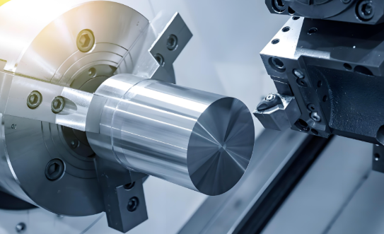
When comparing metal fabrication prototyping to other methods, each approach serves distinct purposes. Understanding the CNC meaning—Computer Numerical Control machining that uses computerized systems to control machinery—helps clarify why different techniques exist. CNC machining excels at precision and uses the exact production materials, preserving bulk mechanical properties. A CNC-machined metal prototype delivers tolerances of ±0.05 mm or better, making it ideal for functional testing where dimensional accuracy matters.
3D printing, on the other hand, offers unmatched geometric freedom. Complex internal channels, organic shapes, and intricate lattice structures that would be impossible to machine become achievable through additive manufacturing. However, metal 3D printed parts typically achieve tolerances of ±0.05 to ±0.1 mm and often require post-processing to match production-level surface finishes.
What sets traditional metal fabrication apart is its direct applicability to production methods. When your final part will be laser cut, bent, and welded, creating a prototype using those exact processes reveals issues that neither CNC machining nor 3D printing would expose. You'll discover how the material behaves during forming, whether weld joints hold under stress, and if your tolerances are actually achievable at scale.
The bottom line? Each prototyping method answers different questions. Smart manufacturers often combine approaches—using 3D printing for rapid design exploration, then transitioning to fabricated prototypes that mirror actual production conditions before committing to full manufacturing.
Core Fabrication Techniques for Metal Prototyping
Now that you understand what a custom metal fabrication prototype is and why it matters, the next question becomes: how exactly is it made? The fabrication method you choose directly impacts prototype accuracy, cost, and turnaround time. Yet many shops mention techniques without explaining when each one actually makes sense for your project.
Let's break down the core cutting and forming processes so you can make informed decisions—and avoid paying for capabilities you don't need.
Cutting Methods Compared for Prototype Accuracy
Every metal cutter leaves behind a kerf—the width of material removed during cutting. This seemingly small detail significantly affects dimensional accuracy and part fit. Understanding kerf differences helps you select the right process for your prototype's tolerance requirements.
Three primary cutting technologies dominate metal prototype fabrication:
- Laser cutting: Uses a focused light beam to cut with surgical precision. According to industry data, laser cutting produces the smallest kerf at approximately 0.3 mm, making it the most accurate option for thin sheet metal fabrication. Ideal for intricate patterns, small holes, and clean edges requiring minimal post-processing.
- Waterjet cutting: Combines high-pressure water with abrasive particles to slice through virtually any material without heat. The kerf measures around 0.9 mm—less precise than laser but with a critical advantage: zero heat-affected zones. This means no warping or material hardening, which is essential for heat-sensitive prototypes.
- Plasma cutting: Creates an electrical arc through compressed gas to melt and blast through conductive metals. With a kerf of approximately 3.8 mm, it's the least precise option but excels at cutting thick steel plate quickly and economically.
| Cutting Method | Precision Level (Kerf) | Material Compatibility | Thickness Range | Best Use Cases |
|---|---|---|---|---|
| Laser Cutting | ~0.3 mm (highest) | Most metals, some plastics | Thin to medium sheets | Intricate details, precision parts, clean edges |
| Waterjet Cutting | ~0.9 mm (high) | Any material (metals, stone, glass, composites) | Wide range including thick materials | Heat-sensitive materials, mixed-material prototypes |
| Plasma Cutting | ~3.8 mm (moderate) | Conductive metals only | 1/2" steel and thicker | Heavy structural components, thick plate work |
When choosing a laser cutter for prototype work, you'll get the fastest turnaround on thin materials with complex geometries. However, if your prototype involves thick aluminum or steel exceeding one inch, plasma cutting delivers the best speed-to-cost ratio. For projects requiring aluminum welding afterward, waterjet cutting prevents the heat distortion that could compromise weld quality.
Forming and Shaping Techniques for Metal Prototypes
Cutting creates flat profiles—but most prototypes need three-dimensional shaping. This is where bending, forming, and stamping transform flat stock into functional parts. Each process shapes metal differently, and understanding these distinctions prevents costly design mistakes.
Bending applies force along a linear axis to create angles and folds in sheet metal. It's the most common forming technique for prototypes because it's fast, precise, and requires minimal tooling.
- Produces consistent angles across long sections
- Works well for brackets, enclosures, and structural components
- Minimum bend radius depends on material thickness and type
- Spring-back compensation must be calculated for accurate final angles
Forming encompasses deeper shaping operations that create curved surfaces, domes, or complex contours. Press brakes, roll forming equipment, and hydraulic presses apply controlled pressure to achieve specific geometries.
- Enables curved profiles impossible with simple bending
- May require custom tooling for unique shapes
- Material stretch and thinning must be accounted for in design
- Best for prototypes with organic or aerodynamic shapes
Stamping uses a die cut machine to punch, blank, or draw metal into predetermined shapes. While stamping tooling costs make it less common for single prototypes, low-volume stamping setups can be cost-effective for small batch prototype runs.
- Produces highly repeatable parts quickly
- Tooling investment only justified for multiple identical prototypes
- Excellent for parts with holes, slots, and embossed features
- Progressive dies can combine multiple operations in one stroke
Match your forming technique to design complexity: simple angles call for bending, curved surfaces need forming, and repetitive features benefit from stamping—even at prototype quantities.
The key to successful prototype fabrication lies in matching methods to your specific requirements. A bracket prototype might only need laser cutting and bending, while a complex housing could require waterjet cutting, multiple forming operations, and secondary machining. Understanding these core techniques helps you communicate effectively with fabrication shops—and spot when they're recommending processes you don't actually need.
What Drives Custom Metal Prototype Pricing
You've selected your fabrication techniques and understand the core processes—but here's where most buyers get blindsided. The quote you receive for a sheet metal prototype isn't just a number pulled from thin air. It's built from multiple cost layers that fabrication shops rarely break down transparently.
Understanding these pricing drivers puts you in control. You'll know which design decisions inflate costs, where negotiation room exists, and how to budget realistically before committing to prototype services.
Material Costs and How Quantity Affects Pricing
Material selection represents the foundation of every prototype quote. But the sticker price of raw metal is just the starting point.
According to industry cost analysis, material costs extend beyond the raw stock itself. The form and availability of your chosen metal matters significantly. Machining from a standard block costs less than working with custom-cast or forged pieces. Sourcing rare alloys can add both lead time and expense.
Here's where sheet metal prototyping economics differ dramatically from production runs:
- Single-piece prototypes: You pay for the entire sheet or block, even if your part only uses 15% of the material. The remaining 85% becomes scrap—and you're absorbing that cost.
- Small batch runs (5-25 pieces): Parts can be nested efficiently on shared stock, spreading material waste across multiple units and lowering per-piece cost by 30-50%.
- Production quantities (100+ pieces): Bulk material purchasing kicks in, and nesting optimization becomes highly efficient—but this rarely applies to prototype phases.
A practical way to control material costs? Design your prototype parts to fit efficiently within standard sheet sizes. A part measuring 13" x 13" wastes significant material from a standard 12" x 12" sheet, forcing a jump to larger stock. Adjusting dimensions by just one inch could cut material costs substantially.
| Cost Variable | Low Impact | Medium Impact | High Impact |
|---|---|---|---|
| Material Type | Cold rolled steel, mild steel | Aluminum alloys (6061, 5052) | Stainless steel, titanium, Inconel |
| Complexity Level | Simple flat cuts, 1-2 bends | Multiple bends, holes, slots | Tight tolerances, deep pockets, welded assemblies |
| Finish Type | Raw/mill finish, light deburring | Bead blasting, brushed finish | Powder coating, anodizing, plating |
| Turnaround | Standard (7-10 days) | Expedited (3-5 days) | Rush (24-48 hours): +40-60% surcharge |
Hidden Expenses in Metal Prototype Projects
The quote for your prototype parts might look reasonable—until invoicing reveals charges that weren't clearly communicated upfront. These hidden costs catch buyers off-guard and can inflate final project expenses by 20-40%.
Setup and programming fees
Every prototype job requires machine setup: loading programs, calibrating equipment, securing fixtures, and running test cuts. For a metal fab shop, this setup time is billable whether you're ordering one piece or fifty. According to fabrication cost studies, setup costs spread across larger orders dramatically reduce per-unit pricing—but for single prototypes, you're absorbing the full setup expense alone.
Tooling charges
Prototype stampings and formed parts may require custom dies or fixtures. While simple bending uses standard tooling, complex shapes often demand specialized equipment. Some shops amortize tooling costs into part pricing; others list them separately. Always ask whether tooling is included—and who owns it afterward.
Design revision cycles
Here's the expense nobody budgets for: changes. Your first prototype reveals a fit issue, so you modify the design. The shop requotes, reprograms, and produces version two. Each iteration carries its own setup fees, material costs, and lead time. Three revision cycles can easily triple your original prototype budget.
Tolerance-driven costs
Specifying tight tolerances on non-critical features forces slower cutting speeds, additional finishing passes, and more frequent quality inspections. Manufacturing experts note that understanding the difference between general and tight tolerances is crucial for managing your budget. Ask yourself: does this hole really need ±0.05 mm, or would ±0.2 mm work just fine?
Use this checklist before requesting quotes to avoid pricing surprises:
- Confirm whether setup/programming fees are included or itemized separately
- Ask about tooling costs for any stamped, formed, or specialized features
- Request a revision policy—how many design changes are included in the quote?
- Review tolerance callouts and relax non-critical dimensions to ±0.2 mm where possible
- Clarify finish specifications—"clean edges" is subjective; "deburr all edges, no secondary finish" is specific
- Factor in shipping costs, especially for rush delivery
- Budget 15-25% contingency for unexpected revisions or complications
The most expensive prototype isn't the one with premium materials—it's the one that requires three revision cycles because specifications weren't clear upfront.
By understanding these cost drivers before engaging with sheet metal prototyping services, you transform from a passive quote recipient into an informed buyer. You'll recognize when pricing seems inflated, know which specifications to tighten or relax, and build realistic budgets that account for the full project lifecycle—not just the initial fabrication.
Selecting the Right Metal for Your Prototype
You've mapped out your fabrication techniques and understand what drives pricing—but none of that matters if you choose the wrong material. The metal you select directly affects prototype performance, manufacturing feasibility, and whether your test results will actually translate to production reality.
Here's the challenge: every metal alloy has unique properties that must be weighed against your specific application needs. According to metallurgy specialists at Ulbrich, the main factors to consider include physical properties, mechanical properties, cost, service requirements, fabrication compatibility, and surface characteristics. Let's break down how these factors apply to prototype material selection.
Common Metals for Prototype Fabrication
Most custom metal fabrication prototypes use one of three material families: aluminum alloys, stainless steels, or carbon steels. Each offers distinct advantages depending on your end-use requirements.
Aluminum and Its Alloys
When weight reduction matters, aluminum sheet metal becomes your go-to choice. Aluminum offers an excellent strength-to-weight ratio—roughly one-third the density of steel while maintaining impressive structural integrity. Common prototype alloys include:
- 6061-T6: The workhorse aluminum alloy with good formability, weldability, and corrosion resistance. Ideal for structural components and general-purpose prototypes.
- 5052: Superior formability makes this alloy perfect for complex bends and deep draws. Excellent corrosion resistance for marine or outdoor applications.
- 7075: Highest tensile strength among common aluminum alloys, approaching some steels. Best for aerospace and high-stress prototypes, though less formable and weldable.
One key advantage for prototype validation: aluminum parts can be anodized to match production finishes exactly. This means your functional testing reflects real-world performance, not just geometric accuracy.
Stainless Steel Grades
When corrosion resistance and durability drive your requirements, stainless steel sheet delivers. The grade you choose depends heavily on your application environment:
- 304 Stainless: The most common grade, offering excellent corrosion resistance for indoor and mild outdoor environments. Good formability and weldability at moderate cost.
- 316 Stainless Steel: Contains molybdenum for superior resistance to chlorides and marine environments. Essential for medical devices, food processing equipment, and coastal applications. Expect 20-30% higher material costs than 304.
- 430 Stainless: A ferritic grade with lower cost and good corrosion resistance. Less formable than 304/316 but suitable for decorative applications and appliances.
For prototypes requiring welding, 316L stainless steel (the low-carbon variant) provides resistance to intergranular corrosion following the welding process—critical for ensuring your welded prototype performs identically to production parts.
Carbon Steel
When raw strength and cost-effectiveness matter most, carbon steel plate delivers. It's the backbone of structural prototyping:
- Mild steel (A36, 1018): Highly formable, easy to weld, and the most economical option. Ideal for structural brackets, frames, and enclosures where corrosion protection comes from coatings.
- Medium carbon (1045): Higher tensile strength for load-bearing applications. Requires more care during welding and forming.
- High carbon/tool steels: Maximum hardness and wear resistance. Difficult to form and weld—typically machined rather than fabricated.
| Material | Tensile Strength (typical) | Cost Relative to Mild Steel | Formability | Typical Prototype Applications |
|---|---|---|---|---|
| Aluminum 6061-T6 | 45,000 psi | 1.5-2x | Good | Structural components, housings, brackets |
| Aluminum 5052 | 33,000 psi | 1.5-2x | Excellent | Complex formed parts, marine components |
| 304 Stainless | 75,000 psi | 3-4x | Good | Food equipment, architectural, general corrosion resistance |
| 316 Stainless Steel | 80,000 psi | 4-5x | Good | Medical devices, marine, chemical processing |
| Mild Steel (A36) | 58,000 psi | 1x (baseline) | Excellent | Structural frames, brackets, general fabrication |
| 1045 Carbon Steel | 82,000 psi | 1.2-1.5x | Moderate | Shafts, gears, load-bearing components |
When comparing brass vs bronze for specialized prototypes, brass offers better machinability and a brighter appearance, while bronze provides superior wear resistance and strength—making it preferred for bushings, bearings, and marine hardware.
Specialty and Refractory Metal Options
Sometimes standard metals simply won't cut it. High-temperature applications, radiation shielding, or extreme corrosion environments demand specialty materials that most fabricators don't discuss.
Refractory Metals
Refractory metals—tungsten, molybdenum, and tantalum—maintain structural integrity at temperatures where conventional metals would fail. According to H.C. Starck Solutions, these materials are increasingly accessible through additive manufacturing, enabling complex prototype geometries that traditional fabrication couldn't achieve.
- Tungsten: The densest common metal with exceptional radiation shielding properties. Used in medical imaging collimators, aerospace ballast, and high-temperature tooling. Difficult to machine conventionally but increasingly 3D-printed for prototype development.
- Molybdenum: Maintains strength at extreme temperatures while being more workable than tungsten. Common in furnace components, heat shields, and electronic applications.
- Tantalum: Exceptional corrosion resistance—virtually immune to most acids. Critical for chemical processing equipment and biomedical implants requiring perfect biocompatibility.
The partnership between H.C. Starck Solutions and additive manufacturing specialists has made refractory metal prototyping more practical. A single-piece tungsten or molybdenum component for medical imaging equipment can now be created to precise specifications much more efficiently than with conventional machining, sintering, or pressing methods.
Other Specialty Materials
Beyond refractory metals, certain applications call for specific alloys:
- Inconel: Nickel-based superalloy for extreme heat and corrosion resistance. Aerospace exhaust systems, gas turbine components.
- Titanium: Exceptional strength-to-weight ratio with corrosion resistance. Medical implants, aerospace structures, high-performance sporting goods.
- Copper alloys: Superior thermal and electrical conductivity. Heat exchangers, electrical components, grounding systems.
For prototypes requiring plastic components alongside metal parts, delrin (acetal) often serves as a complementary material for bushings, insulators, and low-friction surfaces—though that's beyond metal fabrication scope.
Matching Material to End-Use Requirements
Before finalizing your material selection, work through these key criteria:
- Operating environment: Will the part face moisture, chemicals, extreme temperatures, or UV exposure?
- Mechanical loads: What tensile strength, fatigue resistance, and impact toughness does the application demand?
- Weight constraints: Is weight reduction critical enough to justify aluminum sheet or titanium premiums?
- Fabrication compatibility: Can your chosen material be cut, formed, and welded using available processes?
- Production alignment: Will the same material be cost-effective at production volumes, or are you prototyping with a stand-in?
- Finish requirements: Does the surface need plating, anodizing, or coating—and is the material compatible?
The best prototype material isn't always the one you'll use in production—but it should behave similarly enough that your test results remain valid when you scale up.
As Protolabs engineering experts note, engineers and designers will have a higher level of confidence in their analysis as they move through design validation and performance testing when prototypes accurately represent what the production environment will yield. Choose materials that answer your critical questions—even if that means spending more on the prototype phase to avoid production surprises later.
Surface Finishing Options for Metal Prototypes
You've selected the right material and understand fabrication techniques—but your custom metal fabrication prototype isn't complete until you address the surface. The finish you choose determines far more than aesthetics. It affects corrosion resistance, wear performance, and most critically, whether your prototype testing actually reflects how the production part will behave.
Here's what many buyers overlook: applying the wrong finish—or skipping finishing entirely—can invalidate your entire prototype evaluation. A raw aluminum part might perform beautifully in lab testing, then fail spectacularly in field conditions where the production version would have been anodized. Let's explore your options so you can make finish decisions that deliver meaningful test results.
Protective Finishes for Functional Testing
When your prototype needs to survive real-world conditions during evaluation, protective finishes become essential. These treatments add measurable performance characteristics that affect how the part handles stress, corrosion, and environmental exposure.
Powder Coating
Powder coating services deliver one of the most durable protective finishes available. The process electrostatically applies dry powder particles to grounded metal surfaces, then cures them at 350-450°F to form a hard, uniform coating. According to Unionfab's finishing experts, powder coat finishes are more durable than traditional paint, with countless textures and colors available.
- Thickness: 60-120 μm—substantially thicker than liquid paint
- Durability: Excellent scratch, chemical, and UV resistance
- Color options: Virtually unlimited, including metallic and textured finishes
- Limitations: Requires electrically conductive substrates; thickness may affect tight tolerances
For functional testing, powder coating accurately replicates production-level protection. If your final product will be powder coated, prototyping with the same finish ensures your corrosion and wear testing reflects real-world performance.
Anodizing for Aluminum Parts
Anodizing transforms aluminum surfaces through an electrochemical process that thickens the natural oxide layer. Unlike coatings that sit on top of the metal, anodized layers become integral to the aluminum itself—they won't chip, flake, or peel.
According to Boona Prototypes, anodizing delivers layer thicknesses of 10-25 μm for Type II (decorative/protective) and up to 50 μm for Type III (hardcoat) applications. The process also enables vibrant color options—black, red, blue, gold—that become part of the oxide layer rather than surface coatings.
- Corrosion resistance: Excellent for most environments
- Wear resistance: Type III hardcoat approaches tool steel hardness
- Appearance: Clear or colored, maintaining metallic character
- Best for: Anodized aluminum parts requiring durability, aerospace components, consumer electronics housings
For prototypes headed toward aluminum production, testing with the correct anodizing type is critical. A Type II finish behaves differently than Type III under mechanical stress—your prototype testing should match your production intent.
Plating Options
Electroplating deposits thin metal layers onto conductive surfaces, adding specific functional properties. Common plating options for prototypes include:
- Zinc plating: Cost-effective corrosion protection for steel parts. Sacrificial layer protects base metal. Ideal for structural components not requiring decorative finish.
- Nickel plating: Enhances hardness, wear resistance, and corrosion protection. According to industry data, electroless nickel plating achieves hardness up to 1000 HV after heat treatment—excellent for high-precision parts.
- Chrome plating: Maximum hardness and wear resistance with distinctive bright appearance. Common for hydraulic components, wear surfaces, and decorative applications.
Plating typically adds 0.05-0.15 mm thickness. For prototypes with tight tolerances, discuss dimensional allowances with your fabricator before finishing.
Aesthetic Finishes for Presentation Prototypes
Sometimes prototypes serve stakeholder presentations, design reviews, or marketing photography rather than functional testing. These situations call for finishes that prioritize visual impact while still representing production intent.
Brushed Finishes
Brushing creates directional linear grain patterns using abrasive belts or pads. The result is a satin appearance with consistent texture that hides fingerprints and minor scratches—making it popular for visible consumer electronics and appliances.
- Surface roughness: ~0.8-1.6 μm Ra
- Best materials: Aluminum, stainless steel
- Cost: Moderate—mechanical process with reasonable labor time
- Appearance: Professional, industrial-modern aesthetic
Polished Finishes
Mechanical or chemical polishing produces mirror-like reflective surfaces with roughness values as low as 0.2 μm Ra. This premium finish elevates visual appeal and reduces surface friction—ideal for luxury components, medical devices requiring easy cleaning, and premium consumer goods.
Bead Blasting
A stream of fine glass beads creates uniform matte surfaces with subtle texture. Bead blasting removes tool marks, creates consistent appearance, and often serves as preparation for subsequent anodizing or painting. At roughness values of 1.6-3.2 μm Ra, it delivers an attractive satin finish at relatively low cost.
| Finish Type | Durability | Relative Cost | Appearance | Best Applications |
|---|---|---|---|---|
| Powder Coating | Excellent (scratch, UV, chemical resistant) | Moderate | Matte or glossy; unlimited colors | Outdoor equipment, enclosures, consumer products |
| Anodizing (Type II) | Very Good | Moderate | Clear or colored; metallic character | Aluminum housings, consumer electronics |
| Anodizing (Type III) | Excellent (hardcoat) | Higher | Darker, matte | Aerospace, high-wear aluminum components |
| Zinc Plating | Good corrosion protection | Low | Silvery, matte | Steel structural parts, fasteners |
| Nickel Plating | Excellent wear/corrosion | Moderate-High | Silvery, semi-gloss | Precision parts, complex geometries |
| Chrome Plating | Excellent hardness | High | Bright, mirror-like | Hydraulic rods, decorative trim |
| Brushed | Moderate (surface only) | Low-Moderate | Satin with linear grain | Appliances, consumer electronics, signage |
| Polished | Low (requires maintenance) | Moderate-High | Mirror-like gloss | Medical devices, luxury goods, decorative parts |
| Bead Blasted | Moderate | Low | Uniform matte | Pre-coating prep, aesthetic prototypes |
Finish Selection Questions to Ask Before Ordering
Before finalizing your prototype finish, work through these considerations to ensure your choice supports valid testing and realistic production representation:
- Will the production part receive the same finish? If not, how will finish differences affect test validity?
- Does the finish add thickness that could affect critical tolerances?
- Is the chosen finish compatible with your base material? (Anodizing only works on aluminum; some plating requires conductive substrates)
- What environmental conditions will the prototype face during testing?
- Is this prototype for functional validation or stakeholder presentation—or both?
- What lead time does the finish add? (Bead blasting: 1-2 days; Anodizing: 2-4 days; Nickel plating: 3-5 days)
- Can finishes be combined? (Example: bead blast + anodize for textured, colored aluminum)
- What industry standards apply? (Medical devices may require specific biocompatible finishes; food equipment needs FDA-compliant coatings)
The finish that makes your prototype look best isn't always the finish that makes your testing valid. Match your surface treatment to your evaluation goals—not just your presentation schedule.
Surface finishing transforms raw fabricated metal into production-representative prototypes. Whether you need the durability of powder coating, the integrated protection of anodized aluminum, or the visual polish of brushed stainless steel, selecting the right finish ensures your prototype testing delivers actionable insights—not misleading data that falls apart when you scale to production.
From Prototype to Production Success
You've built your prototype sheet metal parts, tested functionality, and confirmed the design works—but here's where many projects stall. The gap between a successful prototype and scalable production isn't just about ordering more pieces. It requires intentional design decisions made during the prototyping phase that most buyers don't consider until it's too late.
According to Approved Sheet Metal's DFM experts, a well-optimized prototype can significantly reduce manufacturing costs, improve lead times, and minimize design revisions during mass production. The key? Treating your custom metal fabrication prototype not as an isolated test piece, but as the foundation for everything that follows.
Design for Manufacturing in the Prototype Phase
Design for Manufacturing (DFM) principles ensure your part can be produced efficiently and consistently at scale. While prototyping often involves manual operations—hand-bent parts, custom machining, single-piece laser cutting—production demands repeatability through automated processes. If you don't design with this transition in mind, you're setting yourself up for costly redesigns.
Here's what DFM-conscious prototype design actually looks like:
- Standard bend radii and hole sizes: A prototype fabricated with non-standard dimensions may work perfectly as a one-off, but production CNC press brakes and turret punches use standard tooling. Designing with common specifications from the start ensures your part can be mass-produced without custom tooling investments.
- Material thickness consistency: According to industry guidelines, sheet metal prototypes are fabricated from single pieces with uniform thickness—typically 0.010" to 0.25". Complex designs requiring variable thickness need alternative approaches like machining or multi-piece assemblies.
- Optimized sheet nesting: While small-batch prototypes rarely prioritize material efficiency, production runs benefit enormously from layouts that minimize scrap. Consider how your part will fit on standard sheet sizes during the design phase.
- Assembly-friendly features: Tabs and slots, self-clinching fasteners (PEM inserts), and modular designs simplify production assembly. A prototype that's easy to assemble manually will scale efficiently without requiring excessive welding or hand-fitting.
For sheet metal prototype fabrication, the transition from laser cutting and manual forming to progressive stamping, turret punching, or roll forming can reduce unit costs dramatically—but only if your design accommodates these efficient processes from the beginning.
Common Prototype Mistakes That Delay Production
Even experienced engineers fall into traps that seem harmless during prototyping but create headaches at scale. According to precision stamping specialists at Jennison Corporation, these design mistakes multiply quickly in high-volume manufacturing.
Over-tolerancing non-critical features
There's a natural tendency to specify tight tolerances everywhere—after all, no one wants sloppy fits. But in metal stamping prototype and fabrication work, unnecessary tightness creates cascading problems. Tighter tolerances demand more complex tooling, slower press speeds, and more frequent die maintenance. Even parts that perform perfectly may be scrapped if inspection shows fractions outside spec.
The solution? Separate truly critical tolerances from those that aren't. A hole determining alignment with a mating component deserves strict limits, but a non-critical bend angle can often allow more variance without affecting function.
Ignoring production process constraints
A prototype designed without considering progressive die requirements often forces multiple dies instead of one—multiplying costs. Features placed awkwardly for strip layouts waste material. Geometries that worked fine for single-piece laser cutting may tear or distort when stamped at production speeds.
Rapid sheet metal prototyping should include early conversations with your fabricator about how the part will be produced at scale. This collaboration prevents discovering production constraints only after tooling is built.
Skipping iteration cycles
The most expensive prototype isn't version one—it's version one rushed directly into production tooling before validation is complete.
Each prototype iteration answers questions that can't be resolved on screen. Form, fit, and function testing reveals issues that simulation misses. Skipping these cycles to save time often means discovering problems in production—where fixes cost 10x more and delay customer deliveries.
Choosing prototype-only materials
Sometimes prototypes use materials that are easy to fabricate but impractical at production volumes. A stainless steel grade that requires surface plating adds cost and steps that a better-selected grade would have eliminated. According to material selection experts, the right material balances formability, strength, and finishing needs—not just prototype convenience.
Failing to involve fabrication partners early
Designs finalized without input from toolmakers and press operators miss optimization opportunities. Features that could be simplified, parts that could be combined, layouts that could reduce waste—these efficiencies only emerge through collaboration. Prototype parts manufacturing benefits enormously when stamping partners review drawings before tooling is built.
Prototype Validation Checklist
Before transitioning any prototype to production, confirm these validation milestones are complete:
- Dimensional verification: All critical dimensions measured and documented against specifications. Non-critical tolerances reviewed for potential relaxation.
- Fit testing: Prototype assembled with mating components. Interface dimensions confirmed. Assembly sequence validated.
- Functional testing: Part subjected to intended loads, cycles, and environmental conditions. Performance data recorded and compared to requirements.
- DFM review completed: Fabrication partner has reviewed design for production scalability. Progressive die compatibility confirmed for stamped parts.
- Material production alignment: Prototype material matches production intent—or documented justification exists for using a substitute.
- Finish validation: Surface treatment applied matches production specification. Finish performance verified under test conditions.
- Secondary operations mapped: All post-fabrication steps (plating, tapping, heat treating, deburring) identified and costed.
- Tooling investment justified: Per-unit cost projections at production volumes validate tooling expenditure.
- Iteration cycles completed: Minimum of two prototype revisions tested, or documented rationale for single-iteration approval.
- Production partner confirmed: Fabricator capable of production volumes has reviewed and approved final design.
When Is Your Prototype Ready for Production?
The decision framework is straightforward but often ignored under schedule pressure. Your prototype sheet metal design is ready for production transition when:
- All functional tests pass with documented results
- DFM feedback has been incorporated and verified
- Material and finish specifications match production intent
- Assembly interfaces are confirmed with mating components
- Cost projections at target volumes meet business requirements
- Your fabrication partner has signed off on manufacturability
According to manufacturing readiness experts, rushing past these gates doesn't save time—it shifts unknowns into production where they become far more expensive to resolve.
The prototype-to-production journey succeeds when you treat every prototype decision as a production decision in disguise. Design with scalability in mind, validate thoroughly, and collaborate early with manufacturing partners. That approach transforms your custom metal fabrication prototype from an expensive test piece into the blueprint for efficient, profitable production.
Industry Applications for Metal Prototypes
Your custom metal fabrication prototype doesn't exist in a vacuum—it exists within an industry with specific standards, certifications, and performance expectations. What passes as acceptable in one sector might fail catastrophically in another. A chassis bracket that performs perfectly for industrial machinery could never qualify for automotive use without meeting additional durability and traceability requirements.
Understanding these industry-specific demands before prototyping saves you from discovering compliance gaps after tooling investments are made. Whether you're working with a local metal parts manufacturer or a specialized small metal parts manufacturer, knowing your sector's requirements ensures your prototype actually validates production readiness.
Automotive Metal Prototype Requirements
Automotive prototyping operates under some of the most demanding quality frameworks in manufacturing. Every chassis component, suspension bracket, and structural element must demonstrate consistent performance across thousands of vehicles—and prove it through documented testing and material traceability.
Key requirements for automotive metal prototypes include:
- IATF 16949 certification: This automotive quality management standard builds on ISO 9001 and adds automotive-specific requirements for defect prevention, traceability, and continuous improvement. According to FirstMold's engineering resources, joint certification of IATF 16949 allows manufacturers to confirm product compliance with industry standards for safety and reliability during prototype evaluation.
- Material traceability: Every piece of steel fabrication for automotive applications must trace back to certified mill sources. Heat numbers, chemical compositions, and mechanical test reports become part of permanent documentation.
- Fatigue testing: Suspension and structural components undergo cyclic loading that simulates years of road stress in compressed timeframes. Prototype designs must accommodate test fixture mounting and strain gauge placement.
- Corrosion validation: Salt spray testing per ASTM B117 subjects prototypes to accelerated environmental exposure. Finish specifications must be validated during prototyping—not assumed.
- Dimensional stability: Automotive tolerances typically run ±0.1 to ±0.25 mm for stamped components, with critical interfaces demanding ±0.05 mm or tighter.
For steel fabricators serving automotive clients, understanding these requirements from the outset prevents costly prototype iterations that could have been avoided with proper specification alignment.
Aerospace and Medical Prototyping Standards
Aerospace Requirements
Aerospace metal prototyping demands weight optimization without compromising structural integrity—a balance that pushes material selection and design complexity to their limits. According to Protolabs' aerospace manufacturing analysis, components may be used in aircraft for more than 30 years with extremely high safety requirements and high levels of thermal or mechanical loading.
Critical aerospace prototype considerations:
- AS9100 certification: The aerospace quality management standard ensures documented processes for design control, risk management, and configuration management throughout prototyping.
- Material certifications: Aerospace-grade alloys like Ti-6Al-4V and Inconel 718 require mill certifications confirming chemical composition and mechanical properties meet specification.
- Non-destructive testing (NDT): Prototypes undergo ultrasonic testing and X-ray inspection to detect internal defects invisible to surface inspection.
- Weight documentation: Every gram matters. Prototype weight must be measured and compared against design targets, with variance analysis for any deviations.
- Thermal cycling validation: Components experience extreme temperature swings between ground and altitude. Prototype testing must simulate these conditions.
Medical Device Prototyping
Medical prototypes face unique challenges that extend beyond mechanical performance. According to PartMfg's medical device guide, over 90% of medical device ideas fail without proper prototyping—and biocompatibility requirements add complexity that other industries don't face.
Essential medical prototype requirements:
- ISO 13485 certification: This medical device quality standard governs design controls, risk management, and documentation throughout the prototype-to-production lifecycle.
- Biocompatibility testing: Any metal contacting tissue or bodily fluids requires cytotoxicity evaluation and corrosion resistance testing in simulated biological environments.
- Precision tolerances: Surgical instruments and implantable devices often demand tolerances of ±0.025 mm or tighter—requiring specialized metal fabrication near me searches to find capable precision shops.
- Surface finish validation: Electropolished surfaces reduce bacterial adhesion and improve cleanability. Ra values below 0.4 μm are common requirements.
- Sterilization compatibility: Prototypes must survive repeated autoclave cycles, gamma radiation, or EtO sterilization without degradation.
| Industry | Typical Tolerance Range | Key Certifications | Critical Material Specs | Primary Testing Focus |
|---|---|---|---|---|
| Automotive | ±0.1 to ±0.25 mm | IATF 16949, ISO 9001 | Traceable steel/aluminum, corrosion resistance | Fatigue, crash simulation, salt spray |
| Aerospace | ±0.05 to ±0.1 mm | AS9100, NADCAP | Certified Ti, Inconel, aerospace aluminum | NDT, thermal cycling, weight validation |
| Medical | ±0.025 to ±0.05 mm | ISO 13485, FDA 21 CFR Part 820 | Biocompatible grades (316L, Ti-6Al-4V ELI) | Biocompatibility, sterilization, surface finish |
| Industrial Equipment | ±0.2 to ±0.5 mm | ISO 9001 | Structural steel, wear-resistant alloys | Load testing, wear analysis, weld inspection |
Industrial Equipment Considerations
While industrial applications generally allow wider tolerances than aerospace or medical, they introduce their own challenges: heavy loads, abrasive environments, and extended service life expectations. Metal fabricators near me serving industrial clients focus on:
- Weld quality inspection: Structural welds undergo magnetic particle or dye penetrant testing to detect surface cracks.
- Load testing: Prototypes are subjected to forces exceeding rated capacity to establish safety margins.
- Wear simulation: Components facing abrasive conditions require accelerated wear testing to validate material selection and surface treatments.
- Environmental durability: Exposure to chemicals, moisture, and temperature extremes must be validated during prototyping.
Your prototype is only as good as its ability to meet industry-specific standards. A functional prototype that can't be certified isn't ready for production—no matter how well it performs on the bench.
The path from prototype to certified production component looks different in every industry. Working with metal fabrication near me partners who understand your sector's specific requirements—and can document compliance throughout the prototyping process—prevents certification surprises that derail production timelines. As you evaluate lead times and turnaround capabilities, remember that industry certification requirements directly impact how quickly your prototype can move toward validated production.
Lead Times and Rapid Prototyping Turnaround
You've navigated material selection, finishing options, and industry certification requirements—but none of that matters if your custom metal fabrication prototype arrives too late for your development schedule. Lead time often becomes the deciding factor between fabrication partners, yet the factors driving those timelines remain frustratingly opaque to most buyers.
Here's the reality: those 2-5 day turnaround claims you see advertised aren't fiction, but they're not universal either. According to Unionfab's metal rapid prototyping analysis, sheet metal prototyping typically delivers within 3-14 business days depending on complexity and finishing requirements—a wide range that reflects how dramatically different project variables affect delivery speed.
Understanding what accelerates versus delays your prototype empowers you to make design decisions that support your timeline rather than sabotage it.
What Enables 5-Day Prototype Delivery
Rapid prototyping metal projects that hit aggressive timelines share common characteristics. When fabricators promise quick turn sheet metal fabrication, they're counting on specific conditions being met—conditions that many buyers unknowingly violate before the project even starts.
The Quote-to-Delivery Timeline
Every rapid sheet metal prototyping project moves through predictable phases. Understanding this sequence reveals where time gets consumed—and where you can compress it:
- Quote and design review (1-2 days): Your fabricator analyzes submitted files for manufacturability, identifies potential issues, and develops pricing. Complex designs requiring DFM feedback extend this phase.
- Material sourcing (0-3 days): Standard materials like mild steel, 6061 aluminum, and 304 stainless typically ship from distributor stock within 24 hours. Specialty alloys, unusual gauges, or certified aerospace materials can add days or weeks.
- Fabrication (1-3 days): Actual cutting, bending, and forming. Simple parts with few operations complete in hours; complex assemblies requiring multiple setups, welding, and secondary machining extend this phase significantly.
- Finishing (1-5 days): Raw parts ship fastest. Bead blasting or brushing adds 1-2 days. Powder coating, anodizing, or plating—often performed by specialized vendors—can add 3-5 days to your timeline.
- Quality inspection and shipping (1-2 days): Final dimensional verification, documentation preparation, and transit time to your facility.
According to Sheet Metal Improvements, the timeline ranges from a few hours to several weeks depending on design complexity, material properties, fabrication techniques, customization level, and quantity. That's not vagueness—it's reality reflecting how dramatically these variables interact.
What Actually Enables Rapid Delivery
Metal rapid prototyping achieves fast turnaround when these conditions align:
- Clean, production-ready files: DXF or STEP files that require no interpretation or correction eliminate back-and-forth review cycles.
- Standard materials in stock: Common gauges of aluminum, steel, and stainless steel ship same-day from most distributors.
- Simple geometry: Parts with minimal bends, standard hole patterns, and no welded assemblies move through fabrication fastest.
- No finishing or minimal finishing: Raw, deburred, or bead-blasted parts skip the finishing queue entirely.
- Flexible tolerances: Standard tolerances (±0.2-0.5 mm) allow faster processing than tight-tolerance work requiring careful inspection.
- Single-piece or small quantities: Programming and setup dominate small-batch time. Fewer parts mean faster completion.
When buyers ask about rapid prototyping metal parts with 5-day delivery, fabricators mentally check these criteria. Miss several, and that timeline stretches accordingly.
Preparing Your Design Files for Faster Turnaround
The single biggest controllable factor in prototype lead time? File quality. According to xTool's prototyping strategies guide, designs that force interpretation, contain errors, or lack critical specifications create delays before fabrication even begins.
Use this checklist before submitting your prototype request:
- File format: Submit native CAD files (STEP, IGES) for 3D parts or DXF/DWG for flat patterns. PDF drawings supplement but shouldn't replace CAD data.
- Flat pattern included: For sheet metal, provide the developed (flat) pattern if possible. This eliminates fabricator calculation time and potential bend allowance discrepancies.
- Material clearly specified: Include alloy designation, temper, and thickness. "Aluminum" isn't a specification; "6061-T6, 0.090" thick" is.
- Tolerances called out: Identify critical dimensions explicitly. General tolerances should be stated (e.g., "±0.25 mm unless noted").
- Finish requirements documented: Specify exact finish—not "powder coated" but "powder coat RAL 9005 matte black, 60-80 μm thickness."
- Quantity and revision level: State how many pieces and identify the drawing revision to prevent quoting outdated designs.
- Hardware and inserts identified: If PEM inserts, standoffs, or other hardware are required, specify part numbers and installation locations.
- Assembly relationships noted: For multi-piece assemblies, indicate mating surfaces and critical interface dimensions.
Rush Orders: Cost Implications
When standard timelines won't work, rush orders become necessary—but they carry significant cost premiums. Expedited rapid prototyping sheet metal typically adds 25-60% to base pricing, reflecting:
- Overtime labor for off-hours fabrication
- Disruption to scheduled production queues
- Premium freight charges for expedited material delivery
- Express shipping for finished parts
Before paying rush premiums, consider whether timeline pressure is self-inflicted. Could cleaner files have prevented design review delays? Would specifying in-stock materials have eliminated sourcing time? Often, the cheapest way to accelerate delivery is removing obstacles rather than paying to overcome them.
The fastest prototype isn't the one with the shortest fabrication time—it's the one that moves through every phase without stopping for clarification, material sourcing, or rework.
By understanding the complete quote-to-delivery timeline and preparing files that eliminate friction, you transform rapid prototyping metal parts from a premium service into an achievable standard. That preparation also positions you well when evaluating fabrication partners—a critical decision that determines whether your prototype project succeeds or stalls.
Choosing the Right Metal Fabrication Partner
You've mastered the technical aspects—material selection, finishing options, lead time optimization—but here's where many prototype projects succeed or fail: partner selection. The fabrication shop you choose determines whether your custom metal fabrication prototype arrives on time, meets specifications, and transitions smoothly to production. Yet most buyers evaluate partners using incomplete criteria, focusing on price while overlooking factors that ultimately matter more.
According to TMCO's fabrication partner analysis, hiring a fabricator isn't just a purchasing decision—it's a long-term investment in the performance and reliability of your products. The right partner contributes engineering support, advanced technology, strong quality systems, and a collaborative approach that adds value beyond the metal itself.
Let's break down what separates exceptional sheet metal prototype services from shops that leave you scrambling.
Evaluating Fabricator Capabilities and Certifications
Capabilities Assessment
Not all fabrication shops near me results deliver equal capability. According to AMG Industries' supplier comparison guide, some shops only cut metal while others outsource machining, finishing, or assembly—leading to delays, communication gaps, and inconsistent quality.
When evaluating metal prototyping services, look for integrated facilities offering:
- Multiple cutting methods: Laser cutting, waterjet, and plasma capabilities allow optimal process selection for your specific material and geometry
- Forming equipment: CNC press brakes, roll forming, and stamping presses for three-dimensional shaping
- Welding capabilities: TIG, MIG, and robotic welding for prototype assemblies
- Secondary operations: CNC machining, tapping, hardware insertion, and deburring in-house
- Finishing options: Powder coating, anodizing, plating—or established relationships with specialty finishers
A partner with modern equipment and automation ensures repeatability, efficiency, and the ability to scale. When your prototype succeeds, you want that same partner handling production—not starting over with a new relationship.
Quality Certifications
Certifications aren't just wall decorations—they document systematic approaches to quality that protect your project. According to industry experts, the best custom metal fabricators follow strict quality processes and use advanced inspection tools to verify accuracy throughout production.
Key certifications to verify:
- ISO 9001: Baseline quality management system demonstrating documented processes and continuous improvement
- IATF 16949: Automotive-specific standard required for chassis, suspension, and structural component suppliers
- AS9100: Aerospace quality management for flight-critical applications
- ISO 13485: Medical device manufacturing requirements
Beyond certifications, ask about inspection capabilities. First-article inspection, in-process dimensional checks, and Coordinate Measuring Machine (CMM) verification indicate precision prototyping and manufacturing capability that ensures your prototype meets specifications—not just approximates them.
Communication Responsiveness
How a fabricator communicates during quoting predicts how they'll communicate during production. According to supplier evaluation experts, good service is gold—quick replies, regular updates, and transparent communication prevent costly surprises and keep projects aligned from start to finish.
Evaluate responsiveness by observing:
- Quote turnaround: Quality fabricators return quotes within 24-48 hours for standard requests. Partners like Shaoyi (Ningbo) Metal Technology offer 12-hour quote turnaround, demonstrating systems optimized for rapid response.
- Technical questions: Do they ask clarifying questions about your application, or just quote what you sent without engagement?
- Problem communication: When issues arise, are you informed proactively—or do you discover problems only when delivery dates slip?
- Single point of contact: Having a dedicated project manager prevents information from falling through organizational cracks
Production Scalability
Your prototype is a stepping stone. Can this partner scale with you? According to fabrication partner guidance, your ideal partner supports both current needs and future growth—scaling from prototypes to full production runs without sacrificing quality.
Ask directly:
- What's your capacity for production volumes of 1,000+ pieces monthly?
- Do you have automated equipment for high-volume runs?
- What lead time changes occur when moving from prototype to production?
- Can you maintain the same quality standards at 10x volume?
For automotive applications, partners like Shaoyi Metal Technology demonstrate this scalability—offering 5-day rapid prototyping alongside automated mass production capabilities, all under IATF 16949 certification. This prototype-to-production continuity eliminates the risky transition between development and manufacturing partners.
The Value of Engineering Support in Prototyping
According to OpenBOM's DFM analysis, the company you contract to make your product should understand its production and assembly processes best—and that understanding should translate into collaborative design support, not just order-taking.
Successful metal prototype fabrication doesn't begin at the machine—it begins with engineering collaboration. A reliable fabricator reviews your drawings, CAD files, tolerances, and functional requirements before cutting metal. This DFM support identifies potential issues when they're cheap to fix: during design, not after tooling.
When evaluating steel prototyping partners, ask whether they provide:
- CAD/CAM support: Can they work with your native file formats and identify manufacturability issues?
- DFM feedback: Will they suggest design modifications that reduce cost or improve quality?
- Material recommendations: Do they advise on optimal alloy selection for your application and production method?
- Prototype testing support: Can they accommodate test fixtures or strain gauge mounting?
- Production transition guidance: Will they help optimize your design for scalable manufacturing?
According to DFM experts, quality does not come out of nowhere—it's engrained in the product before mass production. If your design isn't optimized for production, you'll face quality problems, extended lead times, pricing issues, and customer complaints. Partners offering comprehensive DFM support prevent these cascading failures.
Red Flags When Vetting Fabricators
Experience teaches which warning signs predict project problems. Watch for:
- No questions asked: A fabricator who quotes without asking about your application, tolerances, or end-use doesn't care about your success—they're just processing orders
- Vague lead time commitments: "We'll get it done as soon as possible" isn't a timeline—it's an excuse waiting to happen
- Reluctance to discuss certifications: Quality-focused shops proudly share certification documentation; evasiveness suggests problems
- No DFM feedback: If they don't suggest improvements to your design, they're either not reviewing it carefully or lack the expertise to contribute
- Outsourced core operations: When cutting, forming, finishing, and assembly happen at different facilities, quality control fragments
- No references or case studies: Established fabricators have satisfied customers willing to vouch for them
- Lowest price by far: Dramatically undercutting competitors usually means corners being cut—on materials, inspection, or delivery reliability
| Selection Criteria | What to Look For | Red Flags to Avoid |
|---|---|---|
| Capabilities | Integrated cutting, forming, welding, finishing in-house | Outsources core operations; limited equipment |
| Certifications | ISO 9001 minimum; IATF 16949/AS9100/ISO 13485 for regulated industries | No certifications; reluctance to provide documentation |
| Communication | 24-48 hour quote turnaround; proactive updates; dedicated contact | Slow responses; reactive only; no single point of contact |
| Scalability | Demonstrated prototype-to-production capability; automated equipment | Prototype-only focus; manual processes that won't scale |
| Engineering Support | DFM review included; material recommendations; design optimization | No design feedback; order-taking only |
| Experience | Documented work in your industry; references available | No relevant experience; unwilling to share references |
| Quality Systems | First-article inspection; CMM capability; documented processes | No inspection documentation; "trust us" attitude |
Fabricator Evaluation Checklist
Before committing to a prototype metal stamping or fabrication partner, verify these criteria:
- Capabilities match your project requirements (cutting methods, forming, finishing)
- Relevant certifications documented and current (ISO 9001, IATF 16949, etc.)
- Quote turnaround demonstrates operational efficiency (target: 24-48 hours)
- DFM support offered as part of standard service
- References from similar projects available upon request
- Clear communication protocols with identified project contact
- Production scalability confirmed for anticipated volumes
- Quality inspection processes documented and equipment verified
- Material sourcing reliability demonstrated
- Geographic location appropriate for shipping costs and lead times
The cheapest quote rarely delivers the lowest total cost. Factor in revision cycles, quality issues, communication friction, and production transition challenges when comparing fabrication partners.
Choosing the right metal fabrication partner transforms your prototype project from a procurement transaction into a collaborative development effort. Partners who offer integrated capabilities, documented quality systems, responsive communication, and genuine engineering support—like those meeting IATF 16949 standards with comprehensive DFM services—don't just deliver parts. They deliver confidence that your custom metal fabrication prototype will validate your design, meet your timeline, and transition smoothly into successful production.
Frequently Asked Questions About Custom Metal Fabrication Prototypes
1. How much does a custom metal fabrication prototype cost?
Custom metal fabrication prototype costs vary based on four primary factors: material selection (mild steel is baseline, stainless costs 3-5x more), design complexity (simple cuts vs. tight tolerances and welded assemblies), finishing requirements (raw finish vs. powder coating or anodizing), and turnaround time (rush orders add 25-60% premiums). Single-piece prototypes absorb full setup and material waste costs, while small batches of 5-25 pieces can reduce per-unit costs by 30-50%. Budget an additional 15-25% contingency for revision cycles and hidden expenses like tooling or design changes.
2. What is the difference between sheet metal prototyping and production runs?
Sheet metal prototyping prioritizes learning and design validation, focusing on creating one or a few test pieces to verify form, fit, and function before committing to expensive production tooling. Production runs focus on efficiency, repeatability, and cost-per-unit optimization at high volumes. Prototypes often use manual operations and may allow non-standard processes, while production requires designs optimized for automated equipment like progressive dies and CNC press brakes. The prototype phase should incorporate Design for Manufacturing (DFM) principles to ensure smooth transition to scalable production.
3. How long does sheet metal prototyping take?
Sheet metal prototyping typically takes 3-14 business days depending on complexity and finishing requirements. The timeline breaks down into quote and design review (1-2 days), material sourcing (0-3 days for standard materials), fabrication (1-3 days), finishing (1-5 days for coating or plating), and shipping (1-2 days). Achieving 5-day delivery requires clean production-ready files, standard in-stock materials, simple geometry, minimal finishing, and flexible tolerances. Rush orders can compress timelines but add 25-60% cost premiums.
4. What materials are best for metal prototype fabrication?
The best material depends on your application requirements. Aluminum alloys (6061-T6, 5052) offer excellent strength-to-weight ratios for lightweight applications. Stainless steel grades like 304 provide corrosion resistance for general environments, while 316 stainless steel is essential for marine, medical, or chemical processing applications. Carbon steel (A36, 1018) delivers raw strength and cost-effectiveness for structural prototypes. Specialty applications may require refractory metals like tungsten or molybdenum for extreme temperatures, or titanium for aerospace applications requiring high strength-to-weight ratios.
5. How do I choose the right metal fabrication partner for prototyping?
Evaluate potential partners across five criteria: integrated capabilities (cutting, forming, welding, finishing in-house), relevant certifications (ISO 9001 minimum, IATF 16949 for automotive), communication responsiveness (24-48 hour quote turnaround), production scalability for future volumes, and engineering support including DFM feedback. Red flags include no questions asked during quoting, vague lead time commitments, outsourced core operations, and reluctance to provide references. Partners like Shaoyi Metal Technology demonstrate ideal characteristics with IATF 16949 certification, 12-hour quote turnaround, comprehensive DFM support, and 5-day rapid prototyping to automated mass production capabilities.