 Small batches, high standards. Our rapid prototyping service makes validation faster and easier —

CNC Prototype Costs Exposed: What Shops Won't Tell You Upfront
What CNC Prototype Machining Actually Means for Product Development
Ever wondered how engineers transform a digital concept into a functional part you can actually hold and test? That's exactly what CNC prototype machining delivers. Unlike standard CNC machining focused on high-volume production runs, CNC prototyping prioritizes speed, flexibility, and design validation over mass manufacturing efficiency.
A CNC prototype is a functional test part machined from solid material using computer-controlled cutting tools, created to validate design intent, test fit and function, and identify improvements before committing to full-scale production.
Here's the key distinction: while production machining optimizes for repeatability across thousands of identical parts, prototype machining focuses on rapidly producing one or a handful of parts to verify your design actually works. This difference shapes everything from machine setup to quality expectations.
From Digital Design to Physical Reality
The journey from CAD file to finished CNC prototypes follows a streamlined digital workflow. It starts with your 3D model created in software like SolidWorks, Fusion 360, or CATIA. This digital file contains all the critical information—dimensions, geometry, tolerances, and material specifications.
Next, CAM software translates your design into precise toolpaths that CNC machines follow. According to Precitech, companies adopting this digital prototyping approach can reduce product development time by up to 50%. The result? What once took months now takes days or even hours.
Why Prototyping Demands Precision
Functional testing requires tight tolerances—often within microns—to ensure your prototype behaves exactly like the final production part. Imagine testing a gear assembly where components don't mesh properly because tolerances were too loose. You'd get misleading test results and potentially approve a flawed design.
CNC prototype machining delivers this precision because it produces functional parts from actual production materials, not just visual mockups. Whether you're validating an automotive bracket or a medical device component, you need parts that perform under real-world conditions.
Throughout this guide, you'll learn exactly how the complete CNC machining prototype process works, what materials suit different applications, how costs actually break down, and how to avoid mistakes that inflate your budget. Let's dive into the specifics that machine shops rarely explain upfront.
The Complete CNC Prototyping Process Explained Step by Step
So you've got a brilliant design concept ready. What happens next? Understanding the complete CNC milling process demystifies what happens between uploading your file and receiving a finished prototype. Let's walk through each stage so you know exactly what to expect—and where hidden costs typically emerge.
- CAD File Submission – You provide your 3D design file to the machine shop.
- CAM Programming – Engineers translate your design into machine-readable toolpaths.
- Material Preparation – Raw stock is selected and cut to approximate size.
- Machine Setup – Workholding fixtures secure the material in position.
- CNC Cutting Operations – The machine executes programmed toolpaths to shape your part.
- Quality Verification – Finished parts undergo dimensional inspection.
- Post-Processing – Deburring, cleaning, and any surface finishing complete the prototype.
Each step introduces variables that affect your timeline and budget. Let's break down the critical stages.
Design Preparation and CAD File Requirements
Everything starts with your digital blueprint. The CAD file serves as the foundation for every decision that follows. According to zone3Dplus, CNC machines require precise digital models that define every detail—dimensions, curves, holes, and angles.
Which file formats work best? Machine shops typically accept:
- STEP (.stp, .step) – The universal standard for CNC machining milling projects
- IGES (.igs, .iges) – Widely compatible with most CAM software
- Parasolid (.x_t, .x_b) – Excellent for complex geometry
- Native formats – SolidWorks, Fusion 360, or CATIA files when the shop uses matching software
Design for machining starts before you submit anything. Think about how a cnc mill will actually access each feature. Can a cutting tool reach that internal pocket? Will that thin wall survive the cutting forces? These considerations prevent costly redesigns later.
DFM tips to follow:
- Maintain minimum wall thickness of 0.8mm for metals and 1.5mm for plastics
- Avoid internal undercuts that require special tooling or multiple setups
- Design internal corners with radii matching standard tool diameters
- Keep cavity depths reasonable—typically no more than 4x the tool diameter
- Ensure all features are accessible from standard machining directions
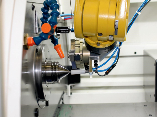
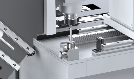
Machine Setup and Material Mounting
Here's where many costs hide. Before any cnc cutting begins, the machine shop must secure your raw material block precisely in position. This fixturing process directly impacts accuracy, cycle time, and ultimately your invoice.
The parts of a cnc mill work together to hold material rigidly while cutting forces try to move it. Common workholding methods include:
- Vises – Standard for rectangular stock; quick setup but limited geometry
- Soft jaws – Custom-machined to match part contours for better grip
- Vacuum fixtures – Ideal for thin, flat parts without clamping marks
- Custom fixtures – Required for complex geometries but add setup cost
For prototypes, shops typically use standard workholding whenever possible to minimize non-recurring expenses. However, complex parts may require sample machining of test fixtures before the actual prototype run—adding both time and cost that rarely appears in initial quotes.
Material mounting also determines how many setups your part needs. A simple bracket machined from one side requires one setup. A complex housing with features on all six faces? That's potentially six setups, each adding time and introducing tolerance stack-up risks.
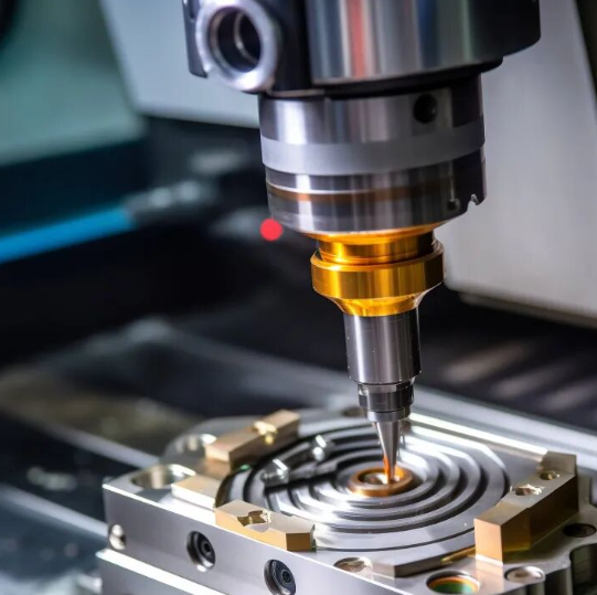
Cutting Operations and Quality Verification
Now the actual machining begins. The CNC machine follows programmed G-code instructions, spinning cutting tools at high speeds while moving them along precise paths. Material is removed in controlled passes until your part emerges from the raw stock.
The cutting sequence typically follows this pattern:
- Roughing – Aggressive cuts remove bulk material quickly, leaving excess stock
- Semi-finishing – Moderate cuts approach final dimensions with smaller tools
- Finishing – Light passes achieve final dimensions and surface quality
- Detail work – Small features, threads, and precision holes are completed
Modern machines achieve tolerances of ±0.01mm when properly programmed and maintained. But tighter tolerances require slower feeds, more passes, and additional inspection—all factors that increase cost.
Quality verification happens throughout the process, not just at the end. Operators check critical dimensions during machining to catch issues early. Final inspection typically uses calipers, micrometers, or coordinate measuring machines (CMMs) depending on tolerance requirements.
Understanding this complete workflow helps you make smarter decisions about your prototype design. But material selection plays an equally crucial role in both cost and functionality—which is exactly what we'll explore next.
Material Selection Guide for CNC Prototypes
Here's a question that shapes your entire project: what material should your CNC prototype be made from? This decision affects everything—cost, lead time, functional testing accuracy, and whether your prototype actually behaves like the final production part. Yet most machine shops gloss over material guidance, leaving you to guess.
The truth? Choosing the wrong material wastes money twice. First on a prototype that doesn't validate what you need, then on redesigning and remaking it. Let's fix that by exploring exactly which materials work best for different prototype purposes.
Metals for Functional and Stress-Testing Prototypes
When your prototype must withstand real mechanical loads, temperature extremes, or assembly torque, metals deliver the performance data you need. Each metal family offers distinct advantages depending on your testing requirements.
Aluminum (6061-T6 and 7075-T6)
Aluminum sheet metal remains the most popular choice for functional prototypes—and for good reason. It machines quickly, costs less than steel or titanium, and offers an excellent strength-to-weight ratio. According to Protolabs' materials comparison guide, Aluminum 6061-T651 works for both CNC milling and turning operations, making it versatile for complex geometries.
- 6061-T6 – General-purpose alloy with good corrosion resistance; ideal for housings, brackets, and structural components
- 7075-T6 – Higher strength for aerospace and high-stress applications; costs more but handles demanding load tests
- 2024-T351 – Excellent fatigue resistance; common in aerospace structural testing
Steel and Stainless Steel
Need maximum durability or corrosion resistance? Steel sheet metal options range from low-carbon mild steel for cost-effective structural parts to stainless grades for harsh environments. Stainless Steel 303 and 316 machine well while offering superior corrosion protection for medical and food-contact applications.
Brass Sheet Metal
Brass excels in prototypes requiring electrical conductivity, antimicrobial properties, or decorative finishes. According to Protolabs' data, Brass C260 works for both sheet metal fabrication and CNC milling, while C360 machines exceptionally well for turned components. Think electrical connectors, valve bodies, and precision fittings.
Titanium (Grade 5, 6Al-4V)
When weight savings and strength matter equally—common in aerospace and medical implant testing—titanium delivers. It costs significantly more than aluminum and machines slower, but provides data impossible to replicate with other materials. Reserve it for prototypes where no substitute exists.
Engineering Plastics for Lightweight Validation
Plastics offer compelling advantages for many prototype applications. According to Hubs' CNC plastics guide, machining plastics provides lighter weight, lower cost, faster machining times, and less tool wear compared to metals. However, they also present unique challenges including heat sensitivity and dimensional instability that require careful material matching.
ABS Plastic Sheets
ABS remains the workhorse plastic for prototype enclosures and housings. It's affordable, machines easily, and provides good impact resistance for ergonomic testing. Based on real machining project data, ABS prototypes typically cost USD 8-15 per piece compared to USD 18-35 for aluminum equivalents.
However, ABS has limitations. It deforms above 80°C and lacks the strength for load-bearing tests. Use it for early-stage concept validation, not functional mechanical testing.
Nylon for Machining (PA 6/6)
Nylon offers superior wear resistance and self-lubricating properties, making it ideal for gears, bushings, and sliding components. Be aware that nylon absorbs moisture, which can cause dimensional changes over time—critical if your prototype requires tight tolerances during extended testing.
Acetal vs Delrin
Here's a common point of confusion: Delrin is DuPont's brand name for acetal homopolymer (POM-H), while generic acetal copolymer (POM-C) offers slightly different properties. Both excel in low-friction applications like gears and bearings. According to Hubs, POM (Delrin/Acetal) is perfect for components where smooth motion and dimensional stability are crucial.
- POM-H (Delrin) – Higher strength and stiffness; better for structural components
- POM-C – Better chemical resistance and dimensional stability; easier to machine
Polycarbonate (PC)
When you need transparency combined with impact resistance, polycarbonate delivers. It's commonly used for display covers, protective housings, and optical applications. Acrylic CNC machining offers even better optical clarity for light diffusers and display windows, though it's more brittle than polycarbonate.
High-Performance Options
For demanding applications, materials like PEEK provide exceptional temperature resistance and mechanical properties approaching metals. However, PEEK costs significantly more and machines slower. Reserve it for prototypes validating aerospace, medical, or high-temperature industrial applications.
Matching Material Properties to Prototype Purpose
Choosing the right material comes down to answering one fundamental question: what exactly are you testing with this prototype?
Consider these decision criteria:
- Functional load testing? Choose materials matching your production intent—aluminum for aluminum parts, steel for steel parts
- Fit and assembly validation? You can often substitute less expensive materials that machine to identical dimensions
- Thermal performance testing? Material thermal conductivity must match production specifications
- Visual/ergonomic evaluation? ABS plastic sheets or similar low-cost options work perfectly
- Chemical exposure testing? PTFE, PVC, or stainless steel depending on the chemicals involved
| Material Type | Typical Applications | Machinability Rating | Cost Tier |
|---|---|---|---|
| Aluminum 6061 | Structural brackets, housings, general mechanical parts | Excellent | Low-Medium |
| Aluminum 7075 | High-stress aerospace and automotive components | Good | Medium |
| Stainless Steel 303/316 | Medical devices, food equipment, corrosive environments | Moderate | Medium-High |
| Brass C360 | Electrical connectors, valve bodies, decorative parts | Excellent | Medium |
| Titanium 6Al-4V | Aerospace structures, medical implants, weight-critical parts | Poor | High |
| ABS | Enclosures, concept models, ergonomic testing | Excellent | Low |
| Nylon 6/6 | Gears, bushings, wear-resistant components | Good | Low |
| Acetal (POM/Delrin) | Precision gears, bearings, low-friction components | Excellent | Low |
| Polycarbonate | Transparent covers, impact-resistant housings | Good | Low-Medium |
| PEEK | High-temp applications, chemical-resistant parts | Moderate | High |
One final consideration: material selection directly impacts whether your prototype data translates to production performance. A plastic prototype won't tell you how an aluminum production part handles thermal cycling. Match your material to your testing goals, not just your budget.
With the right material selected, the next critical decision involves choosing your manufacturing method. Should you use CNC machining, 3D printing, or even injection molding for your prototype? The answer depends on factors many engineers overlook.
CNC Prototyping vs 3D Printing and Injection Molding
You've selected your material, but here's the next question machine shops rarely address honestly: is CNC machining even the right method for your prototype? Sometimes it isn't. Understanding when to choose CNC prototyping over alternatives—and when those alternatives actually serve you better—saves both money and frustration.
Three manufacturing methods dominate the prototyping landscape: CNC machining, 3D printing (additive manufacturing), and injection molding. Each excels in specific scenarios while failing in others. Let's cut through the marketing noise and examine the real trade-offs.
When CNC Beats 3D Printing for Prototypes
3D printing gets tremendous hype, and for good reason—it's revolutionized fast prototyping for complex geometries. But when your prototype needs to actually perform like a production part, CNC machining often delivers what additive methods cannot.
Material properties matter most
Here's the fundamental difference: CNC machining removes material from solid blocks of actual production-grade materials. Your aluminum prototype has the same mechanical properties as an aluminum production part. According to Jiga's manufacturing analysis, CNC machined parts offer "full isotropic strength" with "excellent mechanical properties"—meaning consistent strength in all directions.
3D printed parts? They're built layer by layer, creating inherent weaknesses between layers. Print FDM parts using thermoplastic filaments, and you'll get anisotropic properties—strength varies depending on the direction of applied force. Even SLA printing with photopolymer resins produces parts that may degrade under UV exposure or lack the impact resistance of machined equivalents.
When should you choose CNC over 3D printing?
- Functional load testing – When your prototype must handle real mechanical stress without failure
- Tight tolerance requirements – CNC achieves ±0.01-0.05mm versus ±0.05-0.3mm for most 3D printing technologies
- Superior surface finish – Machined surfaces reach Ra 0.4-1.6 µm; 3D printed parts show visible layer lines at Ra 5-25 µm
- Production-equivalent materials – When testing requires actual aluminum, steel, or engineering plastics
- Heat or chemical exposure – Most 3D printing materials degrade faster than machined alternatives
When 3D printing wins
Let's be honest: 3D printing beats CNC machining in several important scenarios. Complex internal geometries—lattice structures, internal cooling channels, organic shapes—are impossible to machine but straightforward to print. A metal 3D printer using DMLS or SLM technology can produce internal features that would require multiple machined components assembled together.
SLS 3D printing excels at producing multiple prototypes simultaneously, making it cost-effective for testing several design variations in one build. And SLA 3D printing delivers fine details for visual prototypes where surface smoothing post-processing is acceptable.
For early-stage concept models where appearance matters more than function, 3D printing's speed advantage—often same-day turnaround—makes it the smarter choice. Save CNC machining for when functional validation actually requires it.
Injection Molding vs CNC for Low-Volume Validation
Injection moulding seems like a strange comparison for prototyping—it's traditionally a production method. But understanding the cost crossover point helps you plan your entire product development timeline, not just the prototype phase.
According to CrossWind Machining's analysis, the typical product development path follows this progression: R&D components (maybe 5 pieces), several design iterations (up to 5 rounds), small production runs (100-500), then larger volumes. The question isn't whether to use injection molding, but when.
The cost crossover reality
Injection molding requires significant upfront investment in tooling. According to industry data from Rex Plastics cited by CrossWind, mold costs range dramatically:
- Simple single-cavity mold for 1,000 washers annually: $1,000-2,000
- Complex multi-cavity molds for high-volume production: $60,000-80,000+
- Average mold cost for typical projects: approximately $12,000
CNC machining has minimal setup costs spread across each part. The crossover point—where injection molding's lower per-part cost offsets tooling investment—typically occurs between 1,000 and 5,000 parts, depending on complexity and material.
For prototyping quantities under 500 parts, CNC almost always wins on total cost. But here's the nuance: if your design is stable and you're confident about production volumes, early tooling investment accelerates your timeline to market.
Timeline differences
Need 10 prototypes in two weeks? CNC machining is likely your only practical option. Injection mold creation takes weeks to months before producing the first part. However, once tooling exists, injection molding produces parts in seconds—making it unbeatable for production volumes.
Design flexibility considerations
CrossWind's analysis highlights a critical point: "Molds are difficult and many times impossible to modify for changes in design." If your prototype phase involves design iterations—which most do—committing to injection molding tooling prematurely locks you into potentially flawed geometry.
CNC machining accommodates design changes easily. Update your CAD file, regenerate toolpaths, and machine revised prototypes. Each iteration costs time and material, but no tooling investment gets scrapped.
Making the Right Method Decision
Choosing between manufacturing methods shouldn't be guesswork. Use this practical framework based on your specific project requirements:
Choose CNC prototyping when:
- You need production-equivalent material properties for functional testing
- Tolerances tighter than ±0.1mm are required
- Surface finish quality matters for assembly or appearance
- Quantities are under 500 parts
- Design changes are likely during the validation phase
Choose 3D printing when:
- Complex internal geometries or lattice structures are required
- Visual or ergonomic evaluation is the primary goal
- Same-day turnaround matters more than material properties
- Multiple design variations need simultaneous testing
- Cost is the primary constraint and functional accuracy is secondary
Choose injection molding when:
- Design is finalized and stable
- Production quantities will exceed 1,000-5,000 parts
- Per-part cost must be minimized for business viability testing
- Material-specific properties (like living hinges or overmolding) require the actual production process
| Criteria | CNC Machining | 3D Printing (FDM/SLA/SLS) | Injection Molding |
|---|---|---|---|
| Material Options | Wide range: metals, plastics, composites | Limited: polymers, resins, some metals | Broad thermoplastics, some thermosets |
| Tolerance Capability | ±0.01-0.05mm typical | ±0.05-0.3mm typical | ±0.05-0.1mm typical |
| Surface Finish (Ra) | 0.4-1.6 µm (smooth) | 5-25 µm (layer lines visible) | 0.4-1.6 µm (mold-dependent) |
| Lead Time (First Part) | 1-5 days | Hours to 2 days | 4-12 weeks (tooling required) |
| Cost Per Unit (Low Volume) | Medium | Low-Medium | Very High (tooling amortized) |
| Cost Per Unit (High Volume) | High | Very High | Very Low |
| Ideal Quantity Range | 1-500 parts | 1-100 parts | 1,000+ parts |
| Design Flexibility | High (easy file updates) | Very High (no tooling) | Low (tooling modifications costly) |
| Mechanical Strength | Full isotropic properties | Anisotropic, reduced strength | Near-isotropic properties |
| Complex Internal Features | Limited | Excellent | Limited |
Hybrid approaches worth considering
Sometimes the best solution combines methods. 3D printing metal components using DMLS, then CNC finishing critical surfaces, leverages additive geometry freedom with subtractive precision. Similarly, you might 3D print visual prototypes for stakeholder feedback, then CNC machine functional prototypes for engineering validation.
The point isn't loyalty to any single method—it's choosing the right tool for each specific validation need.
Now that you understand which manufacturing method fits your project, the next critical question emerges: what will this actually cost? Understanding the real cost drivers in CNC prototype machining helps you budget accurately and avoid the sticker shock that catches many engineers off guard.
Understanding CNC Prototype Costs and Turnaround Times
Here's the question everyone asks but few machine shops answer directly: how much does it cost to get a metal part made? The honest answer? It depends—but not in the vague, unhelpful way that phrase usually implies. Understanding exactly what drives CNC prototype pricing empowers you to make smarter design decisions and avoid budget surprises.
Unlike production runs where costs become predictable through volume, prototype machining services price each job based on specific project variables. Let's break down what actually influences your invoice.
Key Cost Drivers in Prototype Machining
Every CNC parts quote reflects a combination of factors that interact in sometimes surprising ways. According to Komacut's cost analysis, these variables determine whether your prototype costs hundreds or thousands of dollars:
- Material costs and machinability – Raw material prices vary dramatically. Aluminum machines quickly with minimal tool wear, keeping costs lower. Titanium and stainless steel require slower feeds, specialized tooling, and more machine time—often doubling or tripling machining costs compared to aluminum equivalents.
- Part complexity and geometry – Complex designs with intricate details, tight internal corners, and multiple features require slower machining speeds, frequent tool changes, and potentially custom fixtures. Simple prismatic parts with straightforward geometry cost significantly less than organic or highly detailed components.
- Tolerance requirements – Standard tolerances (±0.1mm) are achievable with normal machining practices. Tighter tolerances (±0.01-0.05mm) demand slower feeds, additional finishing passes, and more rigorous inspection—all adding cost. Only specify tight tolerances on dimensions that functionally require them.
- Number of setups required – Each time your part must be repositioned in the machine adds setup time. A part machined from one side costs less than one requiring features on all six faces. Design consolidation that reduces setups directly reduces cost.
- Surface finish specifications – As-machined finishes are included in base pricing. Polishing, anodizing, plating, or other secondary operations add both time and specialized processing costs.
- Quantity ordered – Setup costs and programming time spread across more parts reduce per-unit cost. According to industry data, bulk material purchases also often attract discounts, further lowering expenses for larger orders.
One often-overlooked factor: machine type significantly impacts hourly rates. According to Komacut's estimates, 3-axis CNC milling runs approximately $35-50 per hour, while 5-axis machining—necessary for complex geometries—can exceed $75-100 per hour. The machine your part requires directly affects your bottom line.
Timeline Expectations for Different Complexities
Rapid CNC prototyping promises speed, but what does that actually mean for your project schedule? Timeline expectations vary dramatically based on part complexity and shop capacity.
Simple parts (1-3 day turnaround)
Basic brackets, plates, and straightforward components with standard tolerances typically ship within days. These require minimal programming, standard tooling, and single-setup machining. If your cnc machining parts fall into this category, expect the fastest turnaround and lowest costs.
Moderate complexity (3-7 day turnaround)
Parts requiring multiple setups, tighter tolerances, or secondary operations like threading and surface finishing fall into this range. According to LS Manufacturing's prototyping guide, standard aluminum prototypes with moderate complexity typically deliver within 3-7 working days.
Complex parts (1-3+ weeks)
Highly intricate components with challenging geometries, exotic materials, or ultra-tight tolerances require extended timelines. Custom fixturing, specialized tooling procurement, and meticulous quality verification all add time. Multi-axis machining for complex surfaces also extends production schedules.
Rush services exist but come at premium pricing—often 1.5x to 2x standard rates. Plan ahead whenever possible to avoid expedite fees that inflate your prototype budget.
Budget Planning for Prototype Projects
Smart budget planning for machined parts goes beyond getting a single quote. Here's practical guidance for managing prototype costs effectively:
Request Design for Manufacturability (DFM) feedback early
Many prototype machining services offer free DFM analysis that identifies cost-driving features before you commit. A radius change here, a tolerance relaxation there—small modifications can significantly reduce machining time without compromising function.
Consider quantity strategically
Need three prototypes? You might get better per-unit pricing ordering five. Setup costs and programming represent fixed expenses regardless of quantity. Spreading these across additional parts often makes ordering spares economically sensible—especially if testing might damage units.
Plan for iteration costs
First prototypes rarely become final designs. According to Fictiv's product development guide, budget for multiple design iterations during validation. A typical product development path includes R&D components (perhaps 5 pieces), followed by several design revision rounds before moving to low-volume production.
Know when to transition from prototyping to production
At some quantity threshold, prototype-style manufacturing becomes inefficient. According to Fictiv's analysis, low-volume production typically refers to quantities ranging from tens to hundreds of thousands of units. Between prototyping and that scale, bridge production runs (100-500 parts) often make sense.
Watch for these transition signals:
- Design is stable with no anticipated changes
- Per-part costs from prototype methods exceed acceptable production margins
- Demand forecasts justify tooling or automation investments
- Quality requirements exceed what prototype-style production can consistently deliver
The key insight? Prototype costs aren't just about minimizing today's invoice—they're about gathering the validation data you need to confidently scale production. Spending more on functional prototypes that accurately predict production performance often saves money long-term by preventing costly design changes after tooling investments.
With cost drivers and timelines now clear, the next critical consideration is understanding how different industries apply CNC prototyping—and the specific requirements that shape their projects.
Industry Applications for CNC Prototype Parts
Ever wonder why aerospace companies pay premium rates for seemingly simple machined brackets? Or why medical device prototypes require documentation that rivals the part's actual manufacturing cost? Each industry brings unique demands to CNC prototype projects—and understanding these requirements helps you anticipate costs, timelines, and quality expectations before your first quote request.
The truth is, a prototype bracket for a consumer product faces entirely different scrutiny than one destined for an aircraft engine bay. Let's explore what makes each industry's prototype requirements distinct and how these factors shape your project planning.
Automotive Prototype Requirements and Standards
Automotive prototypes face a demanding combination of functional testing, assembly validation, and certification requirements. When you're developing components that ultimately affect vehicle safety, the stakes drive rigorous quality expectations.
Functional testing demands
Automotive prototypes must withstand real-world conditions during validation. Think vibration testing, thermal cycling, crash simulation, and fatigue analysis. Your CNC prototype needs to behave exactly like the production part under these stresses—which means material selection and dimensional accuracy become non-negotiable.
Typical tolerance requirements for automotive machining range from ±0.05mm for general components to ±0.01mm for precision drivetrain or engine components. Anything looser, and your test data won't predict production performance.
Certification and traceability needs
Many automotive prototypes require full material certification and process traceability. If you're searching for metal fabricators near me for automotive work, verify they can provide:
- Material test reports (MTRs) documenting alloy composition and mechanical properties
- Process documentation showing machining parameters used
- Dimensional inspection reports for critical features
- First Article Inspection (FAI) when required by OEM specifications
This documentation adds cost but proves essential when prototypes support regulatory submissions or supplier qualification processes.
Aerospace and Medical Precision Demands
If automotive requirements seem stringent, aerospace and medical applications raise the bar considerably. According to LG Metal Works' industry analysis, precision isn't optional in these sectors—"the smallest tolerance deviation can lead to catastrophic consequences, whether in flight-critical components or life-saving surgical tools."
Aerospace prototype specifications
Aerospace prototypes demand tolerances as tight as ±0.0005" (approximately ±0.0127mm) for turbine blades, engine components, and structural brackets. According to industry specifications, 5 axis CNC machining services become essential for complex airfoil geometries and manifold designs that simpler machines cannot produce.
Material requirements add another layer of complexity. Aerospace prototypes commonly use:
- Titanium 6Al-4V – High strength-to-weight ratio for structural components
- Inconel 625/718 – Extreme temperature resistance for engine applications
- Aluminum 7075-T6 – Aerospace-grade aluminum for structural testing
- Stainless 17-4 PH – Corrosion resistance with high strength
Each material presents unique machining challenges. According to LG Metal Works, these materials have "unique thermal expansion, hardness, and chip-forming behaviors—requiring toolpath optimization and expert operator oversight."
Medical device precision requirements
Medical prototypes face both dimensional and regulatory demands. Surgical instruments, implant prototypes, and diagnostic equipment components require biocompatible materials machined to surgical-grade precision.
Common medical-grade materials include:
- Titanium Grade 5 – Biocompatible implant testing
- Stainless Steel 316L – Surgical instrument prototypes
- PEEK – Implantable polymer components
- Cobalt Chrome – Orthopedic implant validation
Quality testing for CNC machined parts in medical applications extends beyond dimensional verification. Surface finish verification, material certification to ASTM or ISO standards, and even sterility-compatible packaging may be required depending on your prototype's intended testing pathway.
Ceramic CNC machining also finds specialized applications in medical devices, particularly for dental implants and wear-resistant joint components where biocompatibility and hardness requirements exceed what metals offer.
Consumer Electronics and Industrial Equipment Applications
Not every prototype needs aerospace-level scrutiny. Consumer electronics and industrial equipment prototypes balance precision requirements against cost efficiency and speed-to-market pressures.
Consumer electronics considerations
Smartphone housings, laptop chassis, and wearable device enclosures demand tight tolerances for assembly fit—but focus more on surface finish quality and cosmetic appearance than extreme dimensional precision. Typical requirements include:
- Tolerances of ±0.05-0.1mm for mating features
- Surface finishes suitable for anodizing or coating (Ra 0.8-1.6 µm)
- Sharp edges and crisp details for consumer-facing surfaces
- Material properties matching production intent (often aluminum 6061 or magnesium alloys)
Sheet metal fabrication techniques often complement CNC machining for electronics enclosures, combining machined features with formed sheet components in hybrid prototypes.
Industrial equipment applications
Robotic components, automation systems, and precision gears require CNC prototypes validated for mechanical performance under industrial conditions. According to Dadesin's industry overview, CNC machining enables "rapid prototyping and functional testing, ensuring these components perform efficiently under industrial conditions."
When searching for cnc machine shops near me for industrial equipment prototypes, prioritize shops with:
- Experience with hardened steels and wear-resistant materials
- Capability for larger workpieces common in industrial applications
- Understanding of geometric dimensioning and tolerancing (GD&T) for functional assemblies
- Quality testing equipment including CMM inspection for dimensional verification
Quality Testing Considerations Across Industries
Regardless of industry, quality testing for CNC machined parts follows a structured verification approach. According to Kesu Group's precision machining guide, modern CMM inspection achieves accuracies of 0.5 microns, enabling verification of even the tightest aerospace tolerances.
Common quality verification methods include:
- Dimensional inspection – Calipers, micrometers, and CMM measurement verify critical dimensions against specifications
- Surface roughness testing – Profilometers quantify surface finish for functional and cosmetic requirements
- Material certification – MTRs and alloy verification ensure prototype materials match production intent
- First Article Inspection (FAI) – Comprehensive documentation packages for regulated industries
- Functional testing – Assembly fit checks, load testing, and performance validation
The key insight? Match your quality requirements to your prototype's actual purpose. Over-specifying inspection adds cost without value; under-specifying risks invalid test data. Communicate your testing intent to your machining partner so they can recommend appropriate verification levels.
Understanding industry-specific requirements helps you set realistic expectations—but even experienced engineers make costly mistakes during prototype development. Let's examine the most common CNC prototyping errors and how to avoid them before they inflate your budget.
Common CNC Prototyping Mistakes and How to Avoid Them
You've selected your material, chosen the right manufacturing method, and found a machine shop. What could go wrong? Unfortunately, plenty. According to XTJ Precision Manufacturing, simple errors in the initial phases can inflate costs dramatically—sometimes by 30% or more. These mistakes not only add unnecessary expenses but also lead to delays, quality issues, and rework.
The good news? Most CNC prototyping errors are entirely preventable once you know what to watch for. Let's examine the costly pitfalls that catch even experienced engineers off guard—and the practical solutions that keep your project on track.
Design Errors That Increase Cost and Delay
Design decisions made before any metal gets cut often determine whether your prototype comes in on budget or blows past estimates. Two errors stand out as the most expensive culprits.
Over-specifying tolerances
This is the single most common mistake that inflates cnc milled parts costs. Designers often specify tight tolerances across entire drawings as a "safety margin," not realizing the manufacturing implications. According to XTJ's real-world data, applying ±0.005mm tolerances universally on an aluminum bracket—when only mounting holes actually required that precision—doubled production time and increased scrap rates. The result? A 25-35% cost increase that was entirely avoidable.
Why does this happen? Tolerance specifications directly affect machining speed, tool selection, and inspection requirements. Tighter tolerances demand:
- Slower feed rates and lighter finishing passes
- More frequent in-process measurement
- Higher scrap rates from minor deviations
- Additional quality verification time
The solution: Apply tight tolerances only where function demands them. Work with your machining partner during Design for Manufacturability (DFM) review to identify which dimensions truly need precision and where tolerances can be relaxed without affecting performance.
Unnecessary geometric complexity
Features that seem simple in CAD can become manufacturing nightmares. Common complexity traps include:
- Deep, narrow pockets – Require specialized long-reach tooling and multiple passes
- Sharp internal corners – Impossible to machine without EDM or specialized processes
- Thin walls without adequate support – Risk deflection and chatter during cutting
- Undercuts and hidden features – May require 4th or 5th axis machining, doubling costs
According to James Manufacturing's prototyping analysis, flawed prototypes from design issues require revisions that increase material waste, labor hours, and retooling costs—with delays that can derail product launch timelines.
The solution: Design with machining in mind. Add fillets to internal corners matching standard tool radii. Keep wall thickness above 0.8mm for metals. Limit pocket depths to 4x the tool diameter. If you're unsure whether a feature is machinable, ask before finalizing your design.
Material Selection Mistakes to Avoid
Choosing materials based on assumptions rather than actual requirements wastes money in two ways: you either overpay for unnecessary properties or get a prototype that can't validate what you need.
Defaulting to premium materials "just in case"
A common scenario: specifying 316 stainless steel for a bracket exposed to mild humidity when aluminum would perform identically in actual use conditions. According to XTJ's project data, switching from unnecessary stainless to aluminum 6061 reduced machining costs by 40-50%—stainless machines slower and causes more tool wear.
Similarly, specifying titanium for non-aerospace applications can multiply costs by 3-5x due to its density and machining difficulty. Reserve expensive materials for prototypes where no substitute exists.
Ignoring machinability ratings
Material strength and machinability are different properties. A material that's perfect for your application might be terrible for machining—driving up costs through:
- Slower cutting speeds required
- Increased tool wear and replacement
- Higher scrap rates from machining challenges
- Longer cycle times per part
The solution: Match material properties to your actual testing requirements, not worst-case assumptions. If you're validating fit and assembly, you may be able to substitute a more machinable material that matches dimensions perfectly. If you're testing mechanical performance, you need production-equivalent materials regardless of machining cost.
Communication Gaps with Machine Shops
Even perfect designs fail when specifications aren't clearly communicated. According to James Manufacturing's research, poor communication between design and production teams results in prototypes that fail to meet design specifications, wasting valuable materials and time.
Incomplete or ambiguous specifications
Common communication failures include:
- Missing tolerance callouts – Shops apply default tolerances that may not meet your needs
- Unclear surface finish requirements – "Smooth" means different things to different people
- Undefined critical features – Without knowing which dimensions matter most, shops can't prioritize
- Absent material specifications – Generic "aluminum" leaves too much to interpretation
The solution: Provide complete documentation including 2D drawings with GD&T callouts, material specifications with acceptable alternatives noted, surface finish requirements using Ra values, and clear identification of critical-to-function dimensions.
Surface Finish: Understanding Your Options and Trade-offs
Surface finish specifications represent a frequently overlooked cost driver. According to Xometry's surface roughness guide, lower Ra values require more machining effort and quality control—significantly driving up costs and time.
Understanding industry-standard options helps you specify appropriately:
- Ra 3.2 µm – Standard commercial finish with visible cut marks; default for most milled parts; suitable for non-critical surfaces
- Ra 1.6 µm – Recommended for stressed parts and light-load mating surfaces; adds approximately 2.5% to production costs
- Ra 0.8 µm – High-grade finish for stress concentration areas and precision fits; adds approximately 5% to costs
- Ra 0.4 µm – Finest available; required for high-tension applications and rapidly rotating components; adds 11-15% to costs
Functional vs. aesthetic trade-offs:
Not every surface needs the same treatment. Milling marks on internal surfaces rarely affect function, while mating surfaces and sealing areas may require finer finishes. Specify finish requirements by surface rather than applying blanket specifications across entire parts.
For cosmetic applications, consider whether as-machined surfaces work or whether secondary operations like bead blasting, anodizing, or polishing are actually necessary. Each adds cost and lead time.
Quick Reference: Common Mistakes and Their Solutions
- Mistake: Applying tight tolerances universally → Solution: Specify precision only on functional dimensions; use DFM review to identify relaxation opportunities
- Mistake: Designing sharp internal corners → Solution: Add radii matching standard tool diameters (typically 1-3mm minimum)
- Mistake: Choosing materials based on strength alone → Solution: Consider machinability ratings and actual application requirements
- Mistake: Submitting 3D files without 2D drawings → Solution: Provide complete documentation with tolerances, surface finishes, and critical feature callouts
- Mistake: Specifying finest surface finish everywhere → Solution: Match finish requirements to functional needs surface by surface
- Mistake: Rushing timeline expectations → Solution: Plan realistic schedules; expedite fees often add 50-100% to costs
- Mistake: Skipping prototype testing validation → Solution: Subject prototypes to rigorous testing before committing to design
Avoiding these common errors positions your prototype project for success. But even with perfect designs and clear specifications, choosing the right manufacturing partner ultimately determines whether your project delivers on its promise. Let's explore what to look for when selecting a CNC prototyping partner.
Choosing the Right CNC Prototyping Partner for Your Project
You've perfected your design, selected the ideal material, and avoided the common mistakes that derail prototype projects. Now comes the decision that ties everything together: which prototype machine shop will actually bring your vision to life? This choice determines whether you receive precision cnc machined prototypes on schedule—or spend weeks chasing quality issues and missed deadlines.
Finding the right cnc prototyping service goes beyond comparing quotes. The lowest price often hides capability gaps that surface only after you've committed. Let's walk through exactly what to evaluate, how to prepare your project for accurate quoting, and how to plan for the transition from machined prototypes to full-scale production.
Evaluating Machine Shop Capabilities
Not all machine shops are created equal. According to PEKO Precision Products, evaluating a precision machine shop requires examining multiple facets including equipment capability, process strategies, quality systems, and business health. A thorough evaluation team typically includes sourcing, quality, and engineering personnel—each assessing different aspects of the partnership.
Equipment and capacity assessment
Start by understanding what machines the shop operates. Can they handle your part's geometry? Do they have sufficient capacity for your timeline? Key questions include:
- What machine types are available (3-axis, 4-axis, 5-axis milling; CNC turning; EDM)?
- What's the maximum workpiece size they can accommodate?
- Do they have redundant capacity to meet deadlines if equipment goes down?
- What spindle speeds and tooling options support your material requirements?
According to TPS Elektronik's precision machining guide, 5-axis machines offer unmatched flexibility for complex parts, machining from multiple angles without repositioning—minimizing tolerance stack-ups that compromise accuracy.
Certifications and quality systems
Certifications signal a shop's commitment to consistent quality. According to PEKO's evaluation guidance, most precision machine shops today hold ISO 9001 certification, while specialized industries require additional credentials like ISO 13485 for medical devices or AS9100 for aerospace applications.
For automotive prototype cnc machining, IATF 16949 certification represents the gold standard. This automotive-specific quality management standard requires documented processes, continuous improvement practices, and rigorous defect prevention. Shops with this certification understand the demanding quality expectations automotive OEMs require.
Beyond certifications, examine the shop's daily quality practices:
- Do they perform First Article Inspection (FAI) on new parts?
- What inspection equipment do they use (CMM, optical comparators, surface profilometers)?
- Do they implement Statistical Process Control (SPC) to monitor production stability?
- Can they provide full traceability documentation when required?
SPC is particularly valuable for prototype cnc machining projects that will transition to production. By monitoring process variation during prototyping, shops can identify and correct issues before they affect production runs—saving you from costly quality problems at volume.
Process optimization and continuous improvement
The best machine shops don't just cut parts—they actively optimize processes. According to PEKO, look for evidence of continuous improvement strategies like Six Sigma, Lean manufacturing, or Kaizen practices. These approaches deliver value through reduced cycle times, lower costs, and improved quality.
Also evaluate how the shop manages workflow. A comprehensive ERP or MRP system indicates organized planning, routing, and delivery management. Without such systems, scheduling chaos often leads to missed deadlines.
Preparing Your Project for Quoting
Want accurate quotes that don't balloon once machining begins? The quality of information you provide directly determines the accuracy of estimates you receive. Incomplete specifications force shops to add contingency pricing—or worse, lead to mid-project cost surprises.
File preparation essentials
Provide complete documentation from the start:
- 3D CAD files – STEP format preferred for universal compatibility; include native files if complex features require clarification
- 2D drawings – Essential for communicating tolerances, surface finishes, and critical dimensions that 3D models don't capture
- Material specifications – Specify exact alloy grades, not just generic material types; include acceptable alternatives if flexibility exists
- Tolerance callouts – Clearly identify which dimensions require tight tolerances and which can accept standard precision
- Surface finish requirements – Specify Ra values for critical surfaces; note whether cosmetic appearance matters
- Quantity needed – Include both initial prototype quantity and anticipated future volumes
Specification tips that prevent surprises
According to UPTIVE Advanced Manufacturing, clear communication between design and production teams prevents prototypes that fail to meet specifications. Apply these practices:
- Identify critical-to-function features explicitly—shops prioritize what you highlight
- Note any secondary operations required (threading, heat treatment, plating, anodizing)
- Specify inspection requirements and documentation needs upfront
- Communicate your testing intent so shops can recommend appropriate verification levels
- Ask about Design for Manufacturability (DFM) review—many shops offer free feedback that reduces costs
When evaluating online cnc machining services versus local shops, consider communication needs. Complex projects benefit from direct engineering discussions; simpler parts may work perfectly through automated quoting platforms.
Scaling from Prototype to Production
The best prototyping relationships extend beyond initial parts. According to UPTIVE's production guide, the prototype-to-production journey involves validating manufacturing processes, identifying bottlenecks, and assessing partners for quality, responsiveness, and lead times during low-volume runs before committing to full-scale production.
Low-volume validation phase
Before scaling to production volumes, many successful projects include a bridge phase of 100-500 parts. This intermediate step catches issues that don't appear in single-prototype production:
- Process consistency across multiple setups
- Tool wear patterns affecting later parts in a batch
- Material lot variations impacting dimensions
- Fixturing approaches that scale efficiently
Document everything during this phase. Changes made to address low-volume issues become your guide for full-scale production optimization.
Choosing partners who scale
Not every rapid prototype machining shop handles production volumes effectively. Evaluate whether your prototyping partner can grow with you:
- Do they have sufficient machine capacity for production quantities?
- Can they maintain prototype-level quality at higher volumes?
- Do they offer supply chain management for ongoing material procurement?
- What's their track record for on-time delivery at production scale?
For automotive applications requiring seamless scaling, facilities like Shaoyi Metal Technology demonstrate how IATF 16949 certification combined with SPC-based quality control enables rapid prototyping with lead times as fast as one working day while maintaining the capability to scale to mass production for chassis assemblies, custom metal bushings, and other precision components.
Key evaluation criteria for choosing a prototyping partner
- Equipment capability – Machines match your geometry, material, and tolerance requirements
- Relevant certifications – ISO 9001 minimum; industry-specific certifications (IATF 16949, AS9100, ISO 13485) when applicable
- Quality systems – Documented processes, SPC monitoring, and appropriate inspection equipment
- Lead time reliability – Track record for on-time delivery; rush capabilities when needed
- Communication quality – Responsive engineering support; clear DFM feedback
- Scalability – Capacity and systems to transition from cnc machining prototyping to production volumes
- Financial stability – Healthy business that will remain a reliable partner long-term
- Supply chain management – Effective material sourcing and secondary operation coordination
- Transparent pricing – Clear cost breakdown; minimum order flexibility for prototypes
Choosing the right cnc prototyping service isn't just about getting parts made—it's about building a manufacturing relationship that supports your entire product development journey. The shop that delivers excellent prototypes while demonstrating production-ready quality systems positions you for success from first article through volume manufacturing.
Take time to evaluate thoroughly. Request facility tours when possible. Ask for references from similar projects. The investment in finding the right partner pays dividends throughout your product's lifecycle—in quality, cost, and peace of mind.
Frequently Asked Questions About CNC Prototype Machining
1. What is a CNC prototype?
A CNC prototype is a functional test part machined from solid production-grade material using computer-controlled cutting tools. Unlike 3D printed prototypes, CNC prototypes offer full isotropic material properties, tighter tolerances (±0.01-0.05mm), and superior surface finishes. This makes them ideal for validating design intent, testing fit and function, and predicting real-world performance before committing to full-scale production.
2. How much does a CNC prototype cost?
CNC prototype costs vary based on material selection, part complexity, tolerance requirements, number of setups, and quantity ordered. Simple aluminum brackets may cost $100-300, while complex multi-axis parts with tight tolerances can exceed $1,000. Key cost drivers include material machinability (titanium costs 3-5x more than aluminum to machine), geometric complexity requiring specialized tooling, and surface finish specifications. Requesting DFM feedback early helps identify cost reduction opportunities.
3. How long does CNC prototyping take?
Turnaround times depend on part complexity. Simple parts with standard tolerances typically ship within 1-3 days. Moderate complexity parts requiring multiple setups take 3-7 days. Complex components with challenging geometries, exotic materials, or ultra-tight tolerances may require 1-3 weeks. Facilities like Shaoyi Metal Technology offer rapid prototyping with lead times as fast as one working day for automotive applications.
4. When should I choose CNC machining over 3D printing for prototypes?
Choose CNC machining when you need production-equivalent material properties for functional testing, tolerances tighter than ±0.1mm, superior surface finish quality, or when testing parts that must withstand real mechanical loads. 3D printing works better for complex internal geometries, same-day visual mockups, or when testing multiple design variations simultaneously. CNC delivers full isotropic strength while 3D printed parts have inherent layer weaknesses.
5. What certifications should a CNC prototype shop have?
At minimum, look for ISO 9001 certification for quality management. For automotive prototypes, IATF 16949 certification indicates the shop meets demanding OEM quality requirements with documented processes and Statistical Process Control (SPC). Aerospace applications require AS9100, while medical devices need ISO 13485. Also verify the shop has appropriate inspection equipment like CMMs and provides material certification documentation when required.